COMPUTER NUMERICAL CONTROL PROGRAMMING BASICS phần 2 docx
Bạn đang xem bản rút gọn của tài liệu. Xem và tải ngay bản đầy đủ của tài liệu tại đây (274.76 KB, 10 trang )
6
We must all do our part; State Directors, District Directors, School
Administrators, and Classroom Teachers to correct a problem long
overdue in technical education.
Steve Krar
CNC Team Leader
Precision Machining Technology
7
The term
numerical control
is a widely accepted and commonly
used term in the machine tool industry. Numerical control (NC)
enables an operator to communicate with machine tools through a
series of numbers and symbols.
NC which quickly became Computer Numerical Control (CNC) has
brought tremendous changes to the metalworking industry. New
machine tools in CNC have enabled industry to consistently
produce parts to accuracies undreamed of only a few years ago.
The same part can be reproduced to the same degree of accuracy
any number of times if the CNC program has been properly pre-
pared and the computer properly programmed. The operating
commands which control the machine tool are executed automati-
cally with amazing speed, accuracy, efficiency, and repeatability.
The ever-increasing use of CNC in industry has created a need for
personnel who are knowledgeable about and capable of preparing
the programs which guide the machine tools to produce parts to
the required shape and accuracy. With this in mind, the authors
have prepared this textbook to take the mystery out of CNC - to
put it into a logical sequence and express it in simple language
that everyone can understand. The preparation of a program is
explained in a logical step-by-step procedure, with practical ex-
amples to guide the student.
Cartesian Coordinate System
Almost everything that can be produced on a conventional ma-
chine tool can be produced on a computer numerical control
machine tool, with its many advantages. The machine tool move-
ments used in producing a product are of two basic types:
point-
to-point
(straight-line movements) and
continuous path
(contouring
movements).
The Cartesian, or rectangular, coordinate system was devised by
the French mathematician and philosopher Rene’ Descartes. With
this system, any specific point can be described in mathematical
Preface
8
terms from any other point along three perpendicular axes. This
concept fits machine tools perfectly since their construction is
generally based on three axes of motion (X, Y, Z) plus an axis of
rotation. On a plain vertical milling machine, the X axis is the
horizontal movement (right or left) of the table, the Y axis is the
table cross movement (toward or away from the column), and the
Z axis is the vertical movement of the knee or the spindle. CNC
systems rely heavily on the use of rectangular coordinates be-
cause the programmer can locate every point on a job precisely.
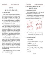
When points are located on a workpiece, two straight intersecting
lines, one vertical and one horizontal, are used. These lines must
be at right angles to each other, and the point where they cross is
called the
origin
, or
zero point
(Fig. 1)
Fig. 1 Intersecting lines form right angles and
establish the zero point (Allen-Bradley)
The three-dimensional coordinate planes are shown in Fig. 2. The
X and Y planes (axes) are horizontal and represent horizontal
machine table motions. The Z plane or axis represents the vertical
tool motion. The plus (+) and minus (-) signs indicate the direction
from the zero point (origin) along the axis of movement. The four
quadrants formed when the XY axes cross are numbered in a
counterclockwise direction (Fig. 3). All positions located in quad-
rant 1 would be positive (X+) and positive (Y+). In the second
quadrant, all positions would be negative X (X-) and positive (Y+).
In the third quadrant, all locations would be negative X (X-) and
negative (Y-). In the fourth quadrant, all locations would be posi-
tive X (X+) and negative Y (Y-).
Fig. 2 The three-dimensional
coordinate planes (axes) used in
CNC. (The Superior Electric
Company)
9
Fig. 3 The quadrants formed when the X and Y axes cross are used to accurately locate
points from the XY zero, or origin, point. (Allen-Bradley)
In Fig. 3 , point A would be 2 units to the right of the Y axis and 2
units above the X axis. Assume that each unit equals 1.000. The
location of point A would be X + 2.000 and Y + 2.000. For point B,
the location would be X + 1.000 and Y - 2.000. In CNC program-
ming it is not necessary to indicate plus (+) values since these are
assumed. However, the minus (-) values must be indicated. For
example, the locations of both A and B would be indicated as
follows:
A X2.000 Y2.000
B X1.000 Y-2.000
Machines Using CNC
Early machine tools were designed so that the operator was
standing in front of the machine while operating the controls. This
design is no longer necessary, since in CNC the operator no
longer controls the machine tool movements. On conventional
machine tools, only about 20 percent of the time was spent remov-
ing material. With the addition of electronic controls, actual time
spent removing metal has increased to 80 percent and even
higher. It has also reduced the amount of time required to bring
the cutting tool into each machining position.
11
Fig. 5 The main axes of a vertical machining center. (Denford Inc.)
Programming Systems
Two types of programming modes, the incremental system and
the absolute system, are used for CNC. Both systems have
applications in CNC programming, and no system is either right or
wrong all the time. Most controls on machine tools today are
capable of handling either incremental or absolute programming.
Incremental program
locations are always given as the distance
and direction from the immediately preceding point (Fig. 6). Com-
mand codes which tell the machine to move the table, spindle,
and knee are explained here using a vertical milling machine as
an example:
X axis
Y axis
Z axis
Positioning
Reference Point Systems
Incremental Absolute
12
Fig. 6 A workpiece dimensioned in the incremental system mode. (Icon Corporation)
• A “X plus” (X+) command will cause the cutting tool to be
located to the right of the last point.
• A “X minus” (X-) command will cause the cutting tool to be lo-
cated to the left of the last point.
• A “Y plus” (Y+) command will cause the cutting tool to be
located toward the column.
• A “Y minus” (Y-) will cause the cutting tool to be located away
from the column.
• A “Z plus” (Z+) command will cause the cutting tool or spindle
to move up or away from the workpiece.
• A “Z minus” (Z-) moves the cutting tool down or into the work-
piece.
In incremental programming, the G91 command indicates to the
computer and MCU (Machine Control Unit) that programming is in
the incremental mode.
Absolute program locations
are always given from a single fixed
zero or origin point (Fig. 7). The zero or origin point may be a
position on the machine table, such as the corner of the worktable
or at any specific point on the workpiece. In absolute dimensioning
and programming, each point or location on the workpiece is given
as a certain distance from the zero or reference point.
13
Fig. 7 A workpiece dimensioned in the absolute system mode. Note: All dimensions are given
from a known point of reference. (Icon Corporation)
• A “X plus” (X+) command will cause the cutting tool to be
located to the right of the zero or origin point.
• A “X minus” (X-) command will cause the cutting tool to be lo-
cated to the left of the zero or origin point.
• A “Y plus” (Y+) command will cause the cutting tool to be
located toward the column.
• A “Y minus” (Y-) command will cause the cutting tool to be lo-
cated away from the column.
In absolute programming, the G90 command indicates to the
computer and MCU that the programming is in the absolute mode.
Point-to-Point or Continuous Path
CNC programming falls into two distinct categories (Fig. 8). The
difference between the two categories was once very distinct.
Now, however, most control units are able to handle both point-to-
point and continuous path machining. A knowledge of both pro-
gramming methods is necessary to understand what applications
each has in CNC.
14
CNC Positioning
Systems
Point-to-Point
or
Positioning
Continuous Path
or
Contouring
Fig. 8 Types of CNC positioning systems (Kelmar Associates)
Point-to-Point Positioning
Point-to-point positioning is used when it is necessary to accu-
rately locate the spindle, or the workpiece mounted on the ma-
chine table, at one or more specific Iocations to perform such
operations as drilling, reaming, boring, tapping, and punching (Fig.
9). Point-to-point positioning is the process of positioning from one
coordinate (XY) position or location to another, performing the
machining operation, and continuing this pattern until all the
operations have been completed at all programmed locations.
Fig. 9 The path followed by point-to-point positioning to reach various programmed points
(machining locations) on the XY axis. (Kelmar Associates)
In Fig. 9 point 1 to point 2 is a straight line, and the machine
moves only along the X axis; but points 2 and 3 require that
motion along both the X and Y axes takes place. As the distance
in the X direction is greater than in the Y direction, Y will reach its
15
position first, leaving X to travel in a straight line for the remaining
distance. A similar motion takes place between points 3 and 4.
Continuous Path (Contouring)
Contouring
, or
continuous path machining
, involves work such as
that produced on a lathe or milling machine, where the cutting tool
is in contact with the workpiece as it travels from one programmed
point to the next. Continuous path positioning is the ability to
control motions on two or more machine axes simultaneously to
keep a constant cutter-workpiece relationship. The programmed
information in the CNC program must accurately position the
cutting tool from one point to the next and follow a predefined
accurate path at a programmed feed rate in order to produce the
form or contour required (Fig. 10)
Interpolation
The method by which contouring machine tools move from one
programmed point to the next is called
interpolation
. This ability to
Fig. 10 Types of contour
machining (A) Simple
contour; (B) complex
contour (Allen Bradley)