Cranes – Design, Practice, and Maintenance phần 3 potx
Bạn đang xem bản rút gọn của tài liệu. Xem và tải ngay bản đầy đủ của tài liệu tại đây (865.46 KB, 35 trang )
Cranes – Design, Practice, and Maintenance50
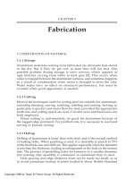
Fig. 3.1.2 Fluid coupling
fluid coupling is an excellent type of drive as it gives smooth accelera-
tion of the complete belt system.
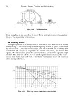
The slipring motor
The slipring motor is a drive which is now little used but it is still worth
mentioning. The alternating current slipring motor is speed-controlled
by resistances. These resistance-steps can be switched on or off by the
controller. If torque is required: the more resistance, the lower the
speed. ‘No resistance’ gives the speed curve of the normal squirrel cage
motor. The brushes of the motor need regular maintenance; the resist-
ances can burn out and rust. Therefore resistances made of stainless
steel have preference.
Fig. 3.1.3 Slipring motor: resistance controlled
Drives; Calculating Motor Powers 51
The Ward–Leonard drive
The Ward–Leonard (WL) drive can be considered as a ‘better DC dri-
ve’. (The DC drive with resistance control is not further described.) The
more complicated WL drive has great advantages compared to drives
with slipring motors or DC motors with resistance control.
The main motor, which is a squirrel cage motor, runs at a constant
speed during the workshift on the crane. It drives a Ward–Leonard
generator for each mechanism. The generator is directly coupled to the
main motor and gives a regulated voltage and current to the respective
motor which forms the drive-element of the crane mechanism. The
speed control of this drive-element can be stepless.
With a three-field generator like the Ward–Leonard–Kra
¨
mer the
maximum torque can be fixed exactly at the desired level. This gives
excellent drives for the hoisting mechanisms of grabbing cranes which
dredge under water and for the drives of cutter-dredgers and similar
devices. Cosphi compensation is not necessary. The Ward–Leonard–
Fig. 3.1.4 Ward–Leonard–Kra
¨
mer (hoist motion)
Cranes – Design, Practice, and Maintenance52
Kra
¨
mer drive has advantages when the current-supply delivery net is
weak or when the main drive element is a diesel engine. A factor, which
must be carefully monitored, is the average accelerating torque. Knowl-
edge of how to design and manufacture these powerful Ward–Leonard
drives has unfortunately been largely lost.
Direct current full-thyristor systems
In the last twenty years the direct current full-thyristor drive has become
the successor to the resistance-controlled AC drives and DC drives and
the Ward–Leonard drives.
The stepless controlled full-thyristor direct current motor is available
for all mechanisms and all capacities. It can be regarded as fool proof.
Regular maintenance is needed to attend to the brushes, and collectors
in the motors. Dust caused by wear and tear of the brushes has to be
removed from time-to-time and the brushes have to be adjusted,
checked, and replaced to prevent breakdown and loss of efficiency.
These motors can be totally enclosed or drip-watertight, self-ventilated
or ventilated by an external, continously running ventilator (force-venti-
lated). Field weakening can occur, normally to a level of approximately
1500 to 2000 rev͞min depending on the power range and field compen-
sation. The normal voltage is 400 V or 500 V. Cosphi compensation is
needed to achieve a cosphi of approximately 0,9.
Alternating current drives with frequency control
To reduce maintenance on the motors as much as possible, the manu-
facturers of electrical systems have developed and now use AC motors
with frequency control. Since 1995 a good working system has been
achieved. AC frequency control is also available for hoisting mechan-
isms using large amounts of power.
The motors are of a simple design. However these are special squirrel
cage motors. The electrical control is somewhat more complicated than
that of the full-thyristor systems, and forced ventilation is not normally
required. Control of these motors is always stepless. Field weakening,
up to 2000 to 2200 rev͞min – based on a four-pole motor, is possible by
increasing the frequency. Torque–speed curves can be adjusted within a
limited range.
It is safe to assume that the research and development of the design
of motors will continue and that further advances will be made. How-
ever, this drive offers the most appropriate and suitable answer for the
next ten years. Cosphi compensation may be necessary to achieve a
cosphi level of approximately 0,9 depending on the type of the drive.
Drives; Calculating Motor Powers 53
Fig. 3.1.5 DC full thyristor
In low speed crane-travelling mechanisms, the option of using one
drive for all the motors under the two sill-beams of the cranes is poss-
ible. Because all the motors will receive the same frequency, synchroniz-
ation between the motors is not absolutely necessary providing that the
wheel loads and the wind loads on each sill-beam of the crane do not
differ significantly. However, it is preferable to use one drive for each
sill-beam and also to make ‘cross-over’ connections between the motors
on the two sill-beams. This ensures exact synchronization.
Warning Especially with AC frequency control, but often also with
DC-Full-Thyristor Control the Electromagnetic Compat-
ability (EMC) due to the Higher Harmonics plays an
important role.
To prevent disturbances by this Electro Magnetic Inter-
ference (EMI) special double-shielded cables must be used.
These screens or shields consist of a copper foil wrapping
and optimized copper wire braiding.
On both ends of the cable special EMC glands must be
used. These must be well-earthed and connected to steel
boxes.
In the bigger motors insulated bearings should also be used.
Cranes – Design, Practice, and Maintenance54
Fig. 3.1.6 AC frequency control: torque–speed diagram for hoisting/lowering
Fig. 3.1.7 2B800 kW Holec AC frequency control motors in the hoisting winch
of a grab-unloader
Drives; Calculating Motor Powers 55
Hydraulic drives
We now concentrate on the Ha
¨
gglunds hydraulic drive, which consists
of a control system; an electric motor; an oil tank; a pump; and a
hydraulic motor. The pump is driven by an electric motor, which runs
with a fixed speed. The oil flow from the pump is controlled by either
a Squashplate or a tilting cylinder block, the angle of which can be
changed by a signal from the control system. The motor pumps the oil
which flows into the motor cylinders and presses the pistons radially
out towards the camring. The speed of the motor is stepless variable.
This system has a low moment of inertia and a high starting torque
(200 to 300 percent of a nominal rated torque). A brake system can
also be provided on these drives.
Fig. 3.1.8 Winches with Ha
¨
gglunds hydraulic drives
Cranes – Design, Practice, and Maintenance56
3.2 Numbers of wire rope sheaves in the hoisting
mechanisms of different reeving systems
As already mentioned in Wire Rope Reeving Systems (Section 2.1),
there are quite a number of reeving systems for hoisting mechanisms.
The main types are considered in Figs 3.2.1(a) to 3.2.1(e).
Fig. 3.2.1(a) Container cranes with machinery trolley. (Hoisting winch on the
trolley.) Number of rope sheaves: minimum
Fig. 3.2.1(b) Container cranes with rope trolley. (Hoisting winch fixed on the
bridge.) Number of rope sheaves: depending on wire rope layout
Drives; Calculating Motor Powers 57
Fig. 3.2.1(c) Grab unloader with main and auxiliary trolley. Number of rope
sheaves: see Fig. 2.1.2
Fig. 3.2.1(d) Level luffing crane. Number of rope sheaves: see sketch
Cranes – Design, Practice, and Maintenance58
Fig. 3.2.1(e) Stacking crane with ‘rope tower’. Number of sheaves: depends
on rope system in trolley
3.3 Calculating the requisite power of the hoisting
motors
For calculating the requisite motor power the following items must be
considered:
(a) the resistance due to normal (nominal) hoisting;
(b) the resistance due to acceleration of the rotating masses;
(c) the resistance due to acceleration of the linear moving masses;
(d) for the hoisting mechanism shown in Fig. 3.2.1(e) the influence
of the angles
α
have to be taken into account, as the forces and
the motor power are multiplied in this wire rope system
with fG
1
cos
α
where
α
is then half of the biggest angle between the wire ropes
when the load is in the highest position.
Drives; Calculating Motor Powers 59
Example 1
The example, shown here, is related to a container crane with a rope
trolley, as in Fig. 3.2.1(b).
Main Characteristics Example
Weight of load:
spreader and
container
or grab and
contents
or hook and
load
Q kg QG66 000 kg
kN QG660 kN
Maximum speed of
the load:
û m͞min ûG60 m͞min
m͞sec ûG1m͞sec
Efficiency of all
gearings and rope
sheaves:
η
t
η
t
G0,90
Motor speed: rev͞min nG783 rev͞min
Inertia moment on
motorshaft from
motor(s);
break sheave(s);
and gearbox:
J
rot
GJ
m
CJ
b
CJ
gb
kg m
2
J
rot
G24C16C6
G46 kg m
2
Acceleration time: sec t
a
G2 sec
Acceleration of the
mass Q:
aG
û
t
m͞sec
2
aG
1
2
G0,5 m͞sec
2
Cranes – Design, Practice, and Maintenance60
Torque (Nm) kiloWatts (kW)
1. Resistance due to
nominal hoisting
(full load at
maximum speed):
N
1
G
Q · û
η
kW N
1
G
660 · 1
0,9
G773 kW
M
1
G
N
1
· 9550
n
Nm M
1
G
773 · 9550
783
G8940 Nm
2. Resistance due to
accelerating the
rotating masses:
ω
G
n · 2 ·
π
60
rad͞sec
ω
G
783 · 2 ·
π
60
G81,95 rad͞sec
M
2
G
J
rot
·
ω
t
a
Nm M
2
G
46 · 81,95
2
G1885 Nm
N
2
G
n · M
2
9550
kW N
2
G
783 · 1885
9550
G154,5 kW
3. Resistance due to
accelerating the
linear masses:
F
3
G
Q · û
g · t
a
kN F
3
G
660 · 1
9,81 · 2
G33,6 kN
N
3
G
F
3
· û
η
kW N
3
G
33,6 · 1
0,9
kW
G37,33 kW
M
3
G
N
3
· 9550
n
Nm M
3
G
37,33 · 9550
783
G455 Nm
Drives; Calculating Motor Powers 61
Torque (Nm) kiloWatts (kW)
Addition:
1. Nominal hoisting M
1
G8940 Nm N
1
G733 kW
2. Acceleration of
the rotating
masses M
2
G1885 Nm N
2
G154,5 kW
3. Acceleration of
the linear moving
masses M
3
G
455 Nm N
3
G
37,33 kW
Total ΣMG11 280 Nm ΣNG924,83 kW
During acceleration, the motor(s) can deliver more torque for a restric-
ted time. This can vary from about 140 percent to as much as 250
percent.
For example: f
a
G160 percentG1,6
The motor(s) must be able to deliver
N
1
G733 kW
resp.
ΣN
f
a
⁄N
1
ΣN
f
a
G
924,83
1,6
G578 kW
(which is lower than N
1
:
so use N
1
G733 kW)
Take motor(s): NG733 kW (2 · 366 kW)
nG783 rev͞min
S
3
– 60 percent rating (see under Section 3.7)
f
a
G160 percent
Field weakening
Let us assume that it is also necessary to hoist (and lower) the load of
200 kN with a speed of ûG120 m͞min (ûG2m͞sec) and an acceleration
time of 4 sec. The motor(s) then run at nG2 · 783G1566 rev͞min.
Cranes – Design, Practice, and Maintenance62
Torque (Nm) kiloWatts (kW)
1. Resistance due to
nominal hoisting:
N
1
G
Q · û
η
t
kW N
1
G
200 · 2
0,9
G444 kW
M
1
G
N · 9550
n
Nm M
1
G
444 · 9550
1566
G2707 Nm
2. Resistance due to
accelerating the
rotating masses:
ω
G
n · 2 ·
π
60
rad͞sec
ω
G
1566 · 2 ·
π
60
G163,9 rad͞sec
M
2
G
J
rot
·
ω
t
a
M
2
G
46 · 163,9
4
G1885 Nm
N
2
G
n · M
2
9550
kW N
2
G
1566 · 1885
9550
G309 kW
3. Resistance due to
accelerating the
linear masses:
F
3
G
Q · û
g · t
a
kN F
3
G
200 · 2
9,81 · 4
G10,19 kN
N
3
G
F
3
· û
η
t
kW N
3
G
10,19 · 2
0,9
G22,6 kW
M
3
G
N
3
· 9550
n
Nm M
3
G
22,6 · 9550
1566
G138 Nm
Drives; Calculating Motor Powers 63
Torque (Nm) kiloWatts (kW)
Addition:
1. Nominal hoisting M
1
G2707 Nm N
1
G444 kW
2. Acceleration of the
rotating masses M
2
G1885 Nm N
2
G309 kW
3. Acceleration of the
linear moving
masses M
3
G
138 Nm N
3
G
22,6 kW
Total ΣMG4370 Nm ΣNG775,6 kW
Take motors: NG733 kW
(2 · 366 kW)
nG783͞1566 rev͞min
S
3
– 60 percent rating (see Section 3.7)
f
a
G160 percent
Fig. 3.3.1 DC FT torque–speed diagram
For grabbing winches
Follow the same calculation method.
Example 2
Assume the weight of the loaded grab is 36 t; the nominal speed
120 m͞min.
Unloader type as Figs 2.1.2 and 3.2.1(c).
With empty grab the speed is 150 m͞min.
Cranes – Design, Practice, and Maintenance64
Torque (Nm) kiloWatts (kW)
1. Resistance due to
nominal hoisting
(full load at
maximum speed):
N
1
G
Q · û
η
kW N
1
G
360 · 2
0,85
G847 kW
M
1
G
N
1
· 9550
n
Nm M
1
G
847 · 9550
783
G10 330 Nm
2. Resistance due to
accelerating the
rotating masses:
ω
G
n · 2 ·
π
60
rad͞sec
ω
G
783 · 2 ·
π
60
G81,95 rad͞sec
M
2
G
J
rot
·
ω
t
a
Nm M
2
G
46 · 81,95
2
G1885 Nm
N
2
G
n · M
2
9550
kW N
2
G
783 · 1885
9550
G154,5 kW
3. Resistance due to
accelerating the
linear masses:
F
3
G
Q · û
g · t
a
kN F
3
G
360 · 2
9,81 · 2
G36,7 kN
N
3
G
F
3
· û
η
kW N
3
G
36,7 · 2
0,85
G86,35 kW
M
3
G
N
3
· 9550
n
Nm M
3
G
86,35 · 9550
783
G1053 Nm
Drives; Calculating Motor Powers 65
Torque (Nm) kiloWatts (kW)
Addition:
1. Nominal hoisting M
1
G10330 Nm N
1
G847 kW
2. Accelerating of the
rotating masses M
2
G1885 Nm N
2
G154,5 kW
3. Accelerating the
linear moving
masses M
3
G
1053 Nm N
3
G
86,4 kW
Total ΣMG13 268 Nm ΣNG1087,9 kW
The motors must deliver NG847 kW and during acceleration, at least
1088 kW.
Take motors: NG2 · (0,55 · 847)
G2 · 466G932 kW
nG783͞1000 rev͞min
S
3
– 100 percent
f
a
G180 percent
Note: To keep the grab well-closed during hoisting you are strongly
advised to give the closing motor more ‘pull’ than the holding motor –
55 percent or 60 percent of the total ‘pull’.
Wet sand or soil can produce suction when the grab is drawn out of
the material, therefore f
a
must be sufficient to counteract this force.
Remark: The acceleration of linear moving masses can also be trans-
ferred into the acceleration of rotating masses:
Acceleration of linear moving masses Transfer
F
3
G
Q · û
g · t
a
kN
JG
30
π
·
û
n
2
·
Q
η
F
3
G
660 · 1
9,81 · 2
JG
30
π
·
1
783
2
·
66 000
0,9
G33,6 kN
G10,92 kgm
2
N
3
G
F
3
· û
η
kW
ω
G
2 ·
π
· n
60
rad͞sec
Cranes – Design, Practice, and Maintenance66
Fig. 3.3.2 4000 ton floating crane ‘Asian Hercules’
Acceleration of linear moving masses Transfer
N
3
G
33,6 · 1
0,9
ω
G
2 ·
π
· 783
60
G82 rad͞sec
G37,33 kW
M
3
G
N
3
· 9550
n
Nm M
3
G
J ·
ω
t
a
Nm
M
3
G
33,73 · 9550
783
M
3
G
10,92 · 82
2
G455 Nm G448 Nm
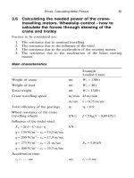
3.4 Calculating the needed power of the trolley
travelling motors
In general, we have 3 types of different systems and calculations.
A Direct driven trolleys or motor trolleys.
B Trolleys, which are pulled by wire ropes.
Drives; Calculating Motor Powers 67
C Rope driven trolleys for grab-unloaders with a main- and an
auxiliary trolley.
For the direct driven or motor trolleys account must be taken of the
possibility of slip between the direct driven wheel and the rail, under
bad weather conditions.
Factors to be considered are:
1. The resistance due to nominal travelling.
2. The resistance due to the current supply- or festoon system.
3. The resistance due to the influence of the wind on the trolley and
the load.
4. The resistance due to the acceleration of the rotating masses.
5. The resistance due to the acceleration of the linear moving
masses.
For systems A and B, the motor trolleys and rope driven trolleys,
we arrive at the following calculation; after checking the main
characteristics.
Main characteristics
Example A Example B
Trolley travelling speed m͞min 150 m͞min 210 m͞min
m͞sec ûG2,5 m͞sec ûG3,5 m͞sec
(Full-motor (Full-rope
trolley) trolley)
Weight of the trolley t W
1
G75 t W
1
G35 t
Weight of the total load t W
2
G55 t W
2
G55 t
Total weight t WtG130 t WtG90 t
Wheel resistance of the
trolley wheels kN͞t fG5kg͞t 0,05 kN͞t
G0,05 kN͞t
Efficiency of gearings
(and rope sheaves)
η
t
Full rope trolley or
semi-rope trolley of a
container crane with the
hoisting mechanism on
the bridge
η
t
G
η
sh
C
η
gearings
η
t
G0,87 to 0,85
Cranes – Design, Practice, and Maintenance68
Fig. 3.4.1
Example A Example B
Full motor trolley of a
crane with the hoisting
winch on the trolley
η
t
G
η
gearings
η
t
G0,90
Influence of the wind:
F
w
GΣ(A · c ·
η
) · q kN
qG150 N͞m
2
–
û
w
G15,5 m͞sec F
w
G18 kN F
w
G12 kN
qG200 N͞m
2
–
û
w
G17,9 m͞sec
qG250 N͞m
2
–
û
w
G20 m͞sec
qG300 N͞m
2
–
û
w
G21,9 m͞sec
qG400 N͞m
2
–
û
w
G25,3 m͞sec
Acceleration time:
t
a
G sec sec t
a
G6 sec t
a
G4 sec
Acceleration:
aG m͞sec
2
m͞sec
2
aG2,5͞6 aG3,5͞4
G0,41 m͞sec
2
G0,875 m͞sec
2
Motor speed n
m
rev͞min n
m
G1500 rev͞min
Wheel diameter D m DG0,8 m Not important,
trolley is rope
driven
Drives; Calculating Motor Powers 69
Example A Example B
Reduction between
motor and wheel i
iG
n
m
·
π
· D
û
iG
1500 ·
π
· 0,8
150
G25,12
J
t
GΣ
mom
of inertia of
the rot. parts kg m
2
J
motors
B
J
break sheaves͞couplings
B
J
gearbox, reduced
B
J
t
kg m
2
J
t
G6 kgm
2
Resistance due to the
current supply- or
festoon-system:
– take 1,5 kN for a
rope driven trolley
and 3–4 kN for a
motor trolley
3.4.1(A) Direct driven trolleys or motor trolleys;
wheel slip control
kN kW
1. Resistance due to
nominal travelling:
F
1
GW
t
· f kN F
1
G130 · 0,05
G6,5 kN
N
1
G
F
1
· û
η
kW N
1
G
6,5 · 2,5
0,9
G18,05 kW
2. Resistance due to
the festoon system:
F
2
kN F
2
G3kN
N
2
G
F
2
· û
η
kW N
2
G
3 · 2,5
0,9
G8,3 kW
Cranes – Design, Practice, and Maintenance70
kN kW
3. Resistance due to
wind:
F
3
GF
w
kN F
3
G18 kN
N
3
G
F
3
· û
η
kW N
3
G
18 · 2,5
0,9
G50 kW
4. Resistance due to
the accelerating of
the rotating masses:
ω
G
n
m
· 2 ·
π
60
rad͞sec
ω
G
1500 · 2 ·
π
60
G157 rad͞sec
M
4
G
J
t
·
ω
t
a
Nm M
4
G
6 · 157
6
G157 Nm
F
4
kN —
(Remains internal
in the drive)
N
4
G
M
4
· n
m
9550
kW N
4
G
157 · 1500
9550
G24,65 kW
5. Resistance due to
the acceleration of
the linear masses:
F
5
G
W
t
· û
t
a
kN F
5
G
130 · 2,5
6
G54,16 kN
N
5
G
F
5
· û
η
kW N
5
G
54,16 · 2,5
0,9
G150,44 kW
Drives; Calculating Motor Powers 71
Addition: Drive forces on Needed motor
(Motor trolley) the wheels (kN) power (kW)
1. Nominal travelling F
1
G6,5 kN N
1
G18,05 kW
2. Festoon system F
2
G3kN N
2
G8,3 kW
3. Wind qG150 N͞m
2
F
3
G18 kN N
3
G50 kW
Total for nominal
travellingCwind ΣFG27,5 kN ΣNG76,35 kW
Addition:
During acceleration kN kW
1. Nominal travelling F
1
G6,5 kN N
1
G18,05 kW
2. Festoon system F
2
G3kN N
2
G8,3 kW
3. Wind qG150 N͞m
2
F
3
G18 kN N
3
G50 kW
4. Acceler. rot. masses,
t
a
G6 sec F
4
G−kN N
4
G24,65 kW
5. Acceler. linear masses,
t
a
G6 sec F
5
G54,16 kN N
5
G150,44 kW
Total, during acceleration: ΣF
a
G81,66 kN ΣN
a
G251,44 kW
(for control of the
slip between rail
and wheel)
The needed motor power must now be greater than ΣNG76,35 kW and
ΣN
a
G251,44͞f
a
. f
a
is the maximum torque of the motors, which should
not be greater than f
a
G2(M
max
G200 percent of M
nom
). So:
ΣN must be greater than ΣNG76,35 kW and ΣN must be
greater than
ΣN
a
G
251,44
2
G125,7 kW
Take ΣNG126 kW.
If 4 wheels are driven, 4 motors each of NG31,5 kW are needed for the
motor trolley.
Cranes – Design, Practice, and Maintenance72
Wheel slip control
The slip between rail and wheels must be controlled for a loaded as well
as an unloaded motor driven trolley:
Loaded trolley Unloaded trolley
Total wheel-loads W
t
G130 t WG130 tA40 t
(container)
W
t
G90 t
Nos. of wheels 4 4
Nos. of driven wheels 4 4
Average wheel load PG130͞4G32,5 t PG90͞4G22,5 t
Maximum traction FG81,66͞4 FG81,66͞4
force per wheel
G20,4 kN G20,4 kN
Needed friction
µ
G0,1 · F͞PM
µ
G0,1 · F͞P
coefficient between
G0,1 ·
20,4
32,5
G0,1 ·
20,4
22,5
wheel and rail allowed
is
µ
G0,12G12 percent
G0,062 G0,0906
G6,2 percent G9,1 percent
3.4.2(B) Trolleys pulled by wire ropes or rope driven trolleys
(We continue with the trolley with the main characteristics mentioned
under Section 3.4.2(A). We repeat these for clarity.)
Trolley travelling speed m͞min 210 m͞min
m͞sec ûG3,5 m͞sec
(full rope trolley)
Weight of the trolley t W
1
G35 t
Weight of the total load t
W
2
G55 t
Total weight t W
t
G90 t
Efficiency of gearings and
rope sheaves
η
t
G0,85
Drives; Calculating Motor Powers 73
Influence of the wind:
F
w
GΣ(A · c ·
η
) · q kN
qG150 N͞m
2
Aû
w
G15,5 m͞sec F
w
G12 kN
qG200 N͞m
2
Aû
w
G17,9 m͞sec
qG250 N͞m
2
Aû
w
G20 m͞sec
qG300 N͞m
2
Aû
w
G21,9 m͞sec
qG400 N͞m
2
Aû
w
G25,3 m͞sec
Acceleration time:
t
a
G sec sec t
a
G4 sec
Acceleration:
aG m͞sec
2
m͞sec
2
aG3,5͞4
G0,875 m͞sec
2
J
t
GΣ
mom
of inertia of the rot. parts kg m
2
J
motors
B
J
brake sheaves͞coupling
B
J
gearbox reduced
B
J
total
GJ
t
kg m
2
J
t
G8kgm
2
Motor rev͞min n
m
G1000 rev͞min
Resistance due to festoon system kN F
2
G1,5 kN
kN kW
B – Rope driven trolley:
calculation
1. Resistance due to
nominal travelling
F
1
GW
t
· f kN F
1
G90 · 0,06
G5,4 kN
N
1
G
F
1
· û
η
kW N
1
G
5,4 · 3,5
0,85
G22,2 kW
(For full-supported
hoist-wire ropes it can
be necessary to
calculate approxi-
mately twice as much
for F
1
and N
1
)
Cranes – Design, Practice, and Maintenance74
kN kW
2. Resistance due to the
festoon system:
F
2
kN F
2
G1,5 kN
N
2
G
F
2
· û
η
kW N
2
G
1,5 · 3,5
0,85
G6,2 kW
3. Resistance due to wind:
F
3
GF
w
kN F
3
G12 kN
N
3
G
F
3
· û
η
kW N
3
G
12 · 3,5
0,85
G49,4 kW
4. Resistance due to the
acceleration of the
rotating masses:
ω
G
n
m
· 2 ·
π
60
rad͞sec
ω
G
1000 · 2 ·
π
60
G104,66 rad͞sec
M
a
G
J
t
·
ω
t
a
Nm M
a
G
8 · 104,66
4
M
4
G209,32 Nm
F
4
kN —
(Remains internal
in drive)
N
4
G
M
a
· n
m
9550
kW N
4
G
209,32 · 1000
9550
G21,92 kW
5. Resistance due to
the acceleration of
the linear masses
F
5
G
W
t
· û
t
a
kN F
5
G
90 · 3,5
4
G78,75 kN
N
5
G
F
5
· û
η
kW N
5
G
78,75 · 3,5
0,85
G324,4 kW