Cranes – Design, Practice, and Maintenance phần 5 ppsx
Bạn đang xem bản rút gọn của tài liệu. Xem và tải ngay bản đầy đủ của tài liệu tại đây (747.62 KB, 35 trang )
Cranes – Design, Practice, and Maintenance120
4. Lowering speed of the load:
û (m͞min) ûG60 m͞min
5. Wire rope speed on the drum:
û
d
G2 · û (m͞min) û
d
G2 · 60G120 m͞min
G(2 · û) : 60 (m͞sec) G120 :60 G2m͞sec
6. Nos. of rev͞min of the drum:
n
d
Gû
d
:(
π
· D
d
) (rev͞min) n
d
G120 : (
π
· 1,2)
G31,84 rev͞min
7. Nos. of rev͞min of the
motor:
n
motor
Gn
d
· i
gb
(rev͞min) n
m
G31,84 · 24,6
G783 rev͞min
8. Inertia moment on the
motorshaft from:
motor(s); brakesheave(s)
and gearbox:
J
rot
GJ
m
CJ
b
CJ
gb
(kg m
2
) J
rot
G24C16C6
G46 kg m
2
9. Reduced inertia moment on
the motorshaft from the
weight of the spreader plus
load:
J
L
G(L · û
2
d
·
η
gb
):
ω
2
1
(kg m
2
) J
L
G(31 350 · 2
2
· 0,94):
783 · 2 ·
π
60
2
J
L
G117 876 :81,95
2
G17,55 kg m
2
10. J
total
GJ
rot
CJ
L
(kg m
2
) J
tot
G46C17,55
G63,55 kg m
2
Brakes 121
11. After pushing the emergency
button, the load is
accelerated by M
1
during ∆t
sec (activating time for the
brake) with ∆
ω
2
(rad͞sec):
∆
ω
2
G
∆t · M
2
J
rot
(rad͞sec) ∆
ω
2
G
(0,3 · 7051)
46
G46 rad͞sec
12. The activated brake starts
mechanical braking after
∆t sec with a rotational speed
on the motorshaft of:
ω
3
G(
ω
1
C
ω
2
)(rad͞sec)
ω
3
G
783 · 2
π
60
C46
ω
1
G(n
m
:60) · 2
π
(rad͞sec)
G81,95C46
G127,95 rad͞sec
13. The numbers of rev͞min of
the motor- and brake-shaft is
then:
n
2
G
ω
3
·
60
2
π
(rev͞min) n
2
G128 ·
60
2
π
G1223 rev͞min
14. The wire rope speed on the
drum is then:
û
d2
G
n
2
n
m
· û
d
(m͞sec) û
d2
G
1223
783
· 2 G3,123 m͞sec
15. The effective brake moment
is:
M
be
G
η
b
· M
b
(Nm) M
be
G0,95 · 19 000
G18 050 Nm
16. The effective braking time is:
t
brake
G
ω
3
· J
total
M
be
AM
1
(sec) t
br
G
128 · 63,55
18 050A7051
G0,740 sec
17. Total braking time:
tG(∆tCt
br
) (sec) tG0,3C0,74G1,04 sec
Cranes – Design, Practice, and Maintenance122
18. Wire rope displacement on the
drum during braking:
S
d
G∆S
1
C∆S
2
(m)
∆S
1
Gdisplacement on the
drum during ∆t (m)
∆S
2
Gdisplacement on the
drum during
deceleration whilst
braking in t
br
sec.
∆S
1
G
û
d
Cû
d2
2
· ∆t (m) ∆S
1
G
2C3,123
2
· 0,3 G0,768 m
∆S
2
G
3,123
2
· 0,74 G1,155 m
∆S
2
G
û
d2
2
· t
br
(m)
S
d
G0,768C1,155G1,923 m
19. Total displacement of
spreader and load during
emergency stop: in lowering
direction (see Fig. 4.2.2)
S
sprCL
GS
d
:2 (m) S
sprCL
G1,923 :2 G0,96 m
Note:
– The winch has: 2 motors;
2 brakes;
1 gearbox;
2 drums.
– The spreader and the load are suspended by eight ropefalls; 4 of
which are fixed on the boom end; the other 4 falls run via wire
rope sheaves to the 2 wire rope drums.
– ∆t can be taken as ∆tG0,3 sec
the worst case for ∆tG0,5 sec.
– The maximal peripherical speed of the brake disc must be
controlled.
The allowed number of brake cycles in an emergency stop can be calcu-
lated as follows:
Dissipated energy per brake cycle: WBGM
br
·
n
2
9,55
·
t
br
2000
(kJ)
Brakes 123
Fig. 4.2.2 Lowering: emergency stop
Nos. of kWh per brake cycle: kWhG
kJ
3593
(kWh)
Allowed numbers of emergency
ZG
û
B
· 2
kWh · 30
(nos)
brake cycles; approximately:
where
û
B
G98 100 mm
3
for SB23 brakes (for a certain brakepad material)
û
B
G244 800 mm
3
for SB28 brakes (for a certain brakepad material)
30Gbrakepad wear per kWh.
The maximum circumference speed of the brake disc which is allowed
is: ûG85 m͞sec for a brake disc of Fe52.3 (S 355 J2 G3).
4.3 Hoisting brakes
Lowering the load; braking by full motor torque
The crane driver is lowering the load and wants to halt the load by
stopping the winch by ‘electric braking’. The full motor torque is to be
Cranes – Design, Practice, and Maintenance124
Fig. 4.3.1 Wire rope scheme
taken as the brake moment. The reeving scheme in Fig. 4.3.1 is assumed
for a container crane.
Example
1. Weight of spreader plus
Load: Q (kg) QG66 000 kg
2. Force on the wire ropes on
the drum:
L (kg) (see Fig. 4.3.1)
LG(Q :2)·
η
s
(kg) LG(66 000 :2) · 0,95
G31 350 kg
η
s
G
η
sheavesCdrum
Gn · 0,99 (nG5)
3. Torque on motorshaft:
M
1
G
L ·
D
drum
2
: i
gb
·
η
gb
M
1
G
31 350 ·
1,2
2
:24,6
· 9,81 (Nm) · 0,94 · 9,81
G7051 Nm
Drum diam. D
drum
G1,2 m
Gearbox reduction i
gb
G24,6
Efficiency gearbox
η
gb
G0,98
3
Brakes 125
4. Lowering speed of the load:
û (m͞min) ûG60 m͞min
5. Wire rope speed on the drum:
û
d
G2 · û (m͞min) û
d
G2 · 60G120 m͞min
G(2 · û): 60 (m͞sec) G120 : 60 G2m͞sec
6. Nos. of rev͞min of the drum:
n
d
Gû
d
:(
π
· D
d
) (rev͞min) n
d
G120 :(
π
· 1,2)
G31,84 rev͞min
7. Nos. of rev͞min of the
motor:
n
motor
Gn
d
· i
gb
(rev͞min) n
m
G31,84 · 24,6
G783 rev͞min
8. Inertia moment on the
motorshaft from:
Motor(s); brake sheave(s)
and gearbox:
J
rot
GJ
m
CJ
b
CJ
gb
(kg m
2
) J
rot
G24C16C6
G46 kg m
2
9. Reduced inertia moment on
the motorshaft from the
weight of the spreader plus
load:
J
L
G(L · û
2
d
·
η
gb
):
ω
2
1
(kg m
2
)
J
L
G(31 350 · 2
2
· 0,94) :
783,2
π
60
2
J
L
G117 876 :81,95
2
G17,55 kg m
2
10. J
total
GJ
rot
CJ
L
(kg m
2
) J
tot
G46C17,55
G63,55 kg m
2
Cranes – Design, Practice, and Maintenance126
11. Braking is immediately
started with the electric
current, delivering the
nominal motor torque.
(The 2 motors deliver in total
NG720 kW at
nG783 rev͞min)
M
nom
G
N · 9550
n
(Nm) M
nom
G
720 · 9550
783
M
nom
GM
el.braking torque
M
nom
GM
eb
G8781 Nm
12.
ω
mot
G
n
60
· 2
π
(rad͞sec)
ω
mot
G
783
60
· 2
π
(rad͞sec)
G81,95 rad͞sec
13. The effective braking time is:
t
brake
G
ω
mot
· J
total
M
eb
AM
1
(sec) t
br
G
81,95 · 63,55
8781A7051
secG3 sec
Fig. 4.3.2 Lowering: electrical braking by full motor torque
Brakes 127
14. Wire rope displacement on
the drum during braking:
S
d
G
1
2
· û
d
· t
br
(m) S
d
G
1
2
· 2 · 3 G3m
15. Total displacement of
spreader and load during
electric braking in hoisting
direction:
S
sprCL
GS
d
:2 (m) S
sprCL
G3:2G1,5 m
4.4 Hoisting brakes
Hoisting the load; braking by full motor torque
The crane driver is hoisting the load and wants to stop the load by
stopping the hoisting winch by ‘electric braking’. We take now the full
motor torque as brake moment. Consider a container crane with the
reeving shown in Fig. 4.4.1 (schematic).
Example
1. Weight of spreader plus
load: Q (kg) QG66 000 kg
2. Force on the wire ropes on
the drum:
L (kg) (see Fig. 4.4.1)
LG(Q :2) ·
η
s
(kg) LG(66 000 :2) · 0,95
G31 350 kg
η
s
G
η
sheavesCdrum
Gn · 0,99 (nG5)
Fig. 4.4.1
Cranes – Design, Practice, and Maintenance128
3. Torque on motorshaft:
M
1
G
L ·
D
drum
2
: i
gb
·
η
gb
M
1
G
31 350 ·
1,2
2
:24,6
· 9,81 (Nm) · 0,94 · 9,81
G7051 Nm
Drum diam. D
drum
G1,2 m
Gearbox reduction i
gb
G24,6
Efficiency gearbox
η
gb
G0,98
3
4. Hoisting speed of the load:
û (m͞min) ûG60 m͞min
5. Wire rope speed on the drum:
û
d
G2 · û (m͞min) û
d
G2:60G120 m͞min
G(2 · û) : 60 (m͞sec) G120 :60G2m͞sec
6. Nos. of rev͞min of the drum:
n
d
Gû
d
:(
π
:D
d
) (rev͞min) n
d
G120 : (
π
· 1,2)
G31,84 rev͞min
7. Nos. of rev͞min of the
motor:
n
motor
Gn
dr
· i
gb
(rev͞min) n
m
G31,84 · 24,6
G783 rev͞min
8. Inertia moment on
motorshaft from:
motor(s); brake sheave(s) and
gearbox:
J
rot
GJ
m
CJ
b
CJ
gb
(kg m
2
) J
rot
G24C16C6
G46 kg m
2
9. Reduced inertia moment on
the motorshaft from the
weight of the spreader plus
load:
J
L
G(L ·
ν
2
d
·
η
gb
):
ω
2
1
(kg m
2
)
J
L
G(31 350 · 2
2
· 0,94):
783,2
π
60
2
J
L
G117 876 :81,95
2
G17,55 kg m
2
Brakes 129
10. J
total
GJ
rot
CJ
L
(kg m
2
) J
tot
G46C17,55
G63,55 kg m
2
11. Braking is immediately
started with the electric
current, delivering the
nominal motor torque.
(The 2 motors deliver
in total
NG720 kW at
nG783 rev͞min)
M
nom
G
N · 9550
n
(Nm) M
nom
G
720 · 9550
783
M
nom
GM
el.braking torque
M
nom
GM
eb
G8781 Nm
12.
ω
mot
G
n
60
· 2
π
(rad͞sec)
ω
mot
G
783
60
· 2
π
(rad͞sec)
G81,95 rad͞sec
13. The effective braking time is:
t
brake
G
ω
mot
· J
total
M
eb
CM
1
(sec) t
br
G
81,95 · 63,55
8781C7051
sec
G0,329 sec
14. Wire rope displacement on
the drum during braking:
S
d
G
1
2
· û
d
· t
br
(m) S
d
G
1
2
· 2 · 0,329 G0,329 m
15. Total displacement of
spreader and load during
electric braking in hoisting
direction:
S
sprCL
GS
d
:2 (m) S
sprCL
G0,329 : 2 G0,165 m
Cranes – Design, Practice, and Maintenance130
Fig. 4.4.2 Hoisting: electrical braking by full motor torque
4.5 Hoisting brakes
Hoisting the load; emergency stop
This is not as dangerous as in the lowering situation. The crane is hoist-
ing the load and something occurs so that the crane driver must use the
emergency push-button. Again, the hoisting mechanism does not brake
electrically, it is an emergency stop. The load is at first decelerated by
gravity, during the short time that is needed to activate the brake. The
activated brake starts braking the load, but is starting from a lower
speed than the normal hoisting speed. Assuming again that it is a con-
tainer crane, with the reeving system shown in Fig. 4.5.1 (schematic).
Example
1. Weight of spreader plus load:
Q (kg) QG66 000 kg
2. Force on the wire ropes on
the drum:
L (kg) (see Fig. 4.5.1)
LG(Q :2) ·
η
s
(kg) LG(66 000 :2) · 0,95
G31 350 kg
η
s
G
η
sheavesCdrum
Gn · 0,99 (nG5)
Brakes 131
Fig. 4.5.1
3. Torque on motorshaft:
M
1
G
L ·
D
drum
2
:i
gb
:
η
gb
M
1
G
31 350 ·
1,2
2
:24,6
· 9,81 (Nm) · 0,94 · 9,81
G7051 Nm
Drum diam. D
drum
G1,2 m
Gearbox reduction i
gb
G24,6
Efficiency gearbox
η
gb
G0,98
3
4. Hoisting speed of the load:
û (m͞min) ûG60 m͞min
5. Wire rope speed on the drum:
û
d
G2 · û (m͞min) û
d
G2 · 60G120 m͞min
G(2 · û) : 60 (m͞sec) G120 :60G2m͞sec
6. Nos. of rev͞min of the drum:
n
d
Gû
d
:(
π
· D
d
) (rev͞min) n
d
G120 : (
π
· 1,2)
G31,84 rev͞min
7. Nos. of rev͞min of the
motor:
n
motor
Gn
d
· i
gb
n
m
G31,84 · 24,6
G783 rev͞min
Cranes – Design, Practice, and Maintenance132
8. Inertia moment on the
motorshaft from:
motor(s); brake sheave(s)
and gearbox:
J
rot
GJ
m
CJ
b
CJ
gb
(kg m
2
) J
rot
G24C16C6
G46 kg m
2
9. Reduced inertia moment on
the motorshaft from the
weight of the spreader plus
load:
J
L
G(L · û
2
d
·
η
gb
):
ω
2
1
(kg m
2
) J
L
G(31 350 · 2
2
· 0,94):
783 · 2 ·
π
60
2
J
L
G117 876 :81,95
2
G17,55 kg m
2
10. J
total
GJ
rot
CJ
L
(kg m
2
) J
tot
G46C17,55G63,55 kg m
2
11. After pushing the emergency
button, the load is
decelerated by M
1
during ∆t
sec (activating time for the
brake) with ∆
ω
2
(rad͞sec):
∆
ω
2
G
∆t · M
1
J
rot
(rad͞sec) ∆
ω
2
G
0,3 · 7051
46
G46 rad͞sec
∆
ω
2
is here negative (negative)
12. The activated brake starts
mechanical braking after
∆t sec with a rotational speed
on the motorshaft of:
ω
3
G
ω
1
A
ω
2
(rad͞sec)—
ω
3
G
783 · 2
π
60
A46
ω
1
G(n
m
:60) · 2
π
(rad͞sec)
G81,95A46
G35,95 rad͞sec
Brakes 133
13. Nos. of rev͞min of the
motor- and brake-shaft is
then:
n
2
G
ω
3
·
60
2
π
(rev͞min) n
2
G36 ·
60
2
π
G344 (rev͞min)
14. The wire rope speed on the
drum is then:
û
d2
G
n
2
n
m
· û
d
(m͞sec) û
d2
G
344
783
· 2 G0,88 m͞sec
15. The effective brake moment
is:
M
be
G
η
b
· M
b
(Nm) M
be
G0,95 · 19 000
G18 050 Nm
16. The effective braking time is:
t
brake
G
ω
3
· J
total
M
be
CM
1
(sec) t
br
G
36 · 63,55
18 050C7051
G0,091 sec
17. Total braking time:
tG(∆tCt
br
) (sec) tG0,3C0,091G0,391 sec
18. Wire rope displacement on the
drum, during braking:
S
d
G∆S
1
C∆S
2
(m)
∆S
1
Gdisplacement on the
drum during ∆t (m)
∆S
2
Gdisplacement on the
drum during
deceleration while
braking in t
br
sec
∆S
1
G
û
d
Cû
d2
2
· ∆t (m) ∆SG
2C0,88
2
· 0,3 G0,432 m
∆S
2
G
û
d2
2
· t
br
(m) ∆S
2
G
0,88
2
· 0,091 G0,04 m
S
d
G0,432C0,04G0,472 m
Cranes – Design, Practice, and Maintenance134
19. Total displacement of the
spreader and load during
emergency stop in hoisting
direction (see Fig. 4.5.2):
S
sprCL
GS
d
:2 (m) S
sprCL
G0,472 : 2 G0,236 m
Fig. 4.5.2 Hoisting: emergency stop
4.6 Svendborg brakes
Svendborg brakes of Denmark manufacture disc brakes of a special
construction which results in an activating time of ∆tG0,1 sec instead
of ∆tG0,3 to 0,5 sec, when thrustor-activated disc brakes are used.
From Section 4.2, Lowering the Load; Emergency Stop (example
point 11), we come to the following calculation:
With ∆t G0,3 sec With ∆tG0,1 sec
11. After pushing the
emergency button, the load
is accelerated by M
1
during
∆t sec (activating time for
the brake) with ∆
ω
2
(rad͞
sec):
∆
ω
2
G
∆t · M
1
J
rot
(rad͞sec) ∆
ω
2
G
(0,3 · 7051)
46
∆
ω
2
G
(0,1 · 7051)
46
G46 rad͞sec G15,3 rad͞sec
Brakes 135
Fig. 4.6.1 Svendborg brakes
12. The activated brake starts
mechanical braking after ∆t
sec with a rotational speed
on the motorshaft of:
ω
3
G(
ω
1
C
ω
2
) (rad͞sec)
ω
3
G
783 · 2
π
60
C46
ω
3
G
783 · 2
π
60
C15,3
ω
1
G(n
m
:60) · 2
π
(rad͞sec)
G81,95C46 G81,95C15,3
G127,95 rad͞sec G97,25 rad͞sec
13. The numbers of rev͞min of
the motor- and brake-shaft
is then:
n
2
G
ω
3
·
60
2
π
(rev͞min) n
2
G128 ·
60
2
π
G1223 rev͞min n
2
G97,25 ·
60
2
π
G929 rev͞min
14. The wire rope speed on the
drum is then:
û
d2
G
n
2
n
m
· û
d
(m͞sec) û
d2
G
1223
783
· 2 G3,123 m͞sec û
d2
G
929
783
· 2 G2,37 m͞sec
15. The effective brake
moment is:
M
be
G
η
b
· M
b
(Nm) M
be
G0,95 · 19 000 M
be
G0,95 · 19 000
G18 050 Nm G18 050 Nm
Cranes – Design, Practice, and Maintenance136
16. The effective braking time
is:
t
brake
G
ω
3
· J
total
M
be
AM
1
(sec) t
br
G
128 · 63,55
18 050A7051
G0,740 sec t
br
G
97,25 · 63,55
18 050A7051
G0,56 sec
17. Total braking time:
tG(∆tCt
b
) (sec) tG0,3C0,74 G1,04 sec tG0,1C0,56 G0,66 sec
18. Wire rope displacement on
the drum during braking:
S
d
G∆S
1
C∆S
2
(m)
∆S
1
Gdisplacement on the
drum during ∆t (m)
∆S
2
Gdisplacement on the
drum during
deceleration whilst
braking in t
br
sec
∆S
1
G
û
d
Cû
d2
2
· ∆t (m) ∆S
1
G
2C3,123
2
· 0,3 G0,768 m ∆S
1
G
2C2,37
2
· 0,1 G0,22 m
∆S
2
G
û
d2
2
· t
br
(m) ∆S
2
G
3,123
2
· 0,74 G1,155 m ∆S
2
G
2,37
2
· 0,56 G0,66 m
S
d
G0,768C1,155G1,923 m S
d
G0,22C0,66G0,88 m
19. Total displacement of
spreader and load during
emergency stop: in
lowering
direction (see Fig. 4.2.2)
S
sprCL
GS
d
:2 (m) S
sprCL
G1,923 :2G0,96 m S
sprCL
G0,88 :2G0,44 m
4.7 Calculating the brake time and braking distance
of a crane
Take a stacking crane running at high speed as an example.
Main characteristics
Weight of crane (t) W
1
G650 t
Weight of the load (t) W
2
G40 t
Total weight (t) W
t
G690 t
Crane travelling speed (m͞min) (ûG140 m͞min)
(m͞sec) ûG2,33 m͞sec
Crane travel resistance (kN͞t) fG5kg͞tG0,05 kN͞t
(take during braking
fG3kg͞tG0,03 kN͞t)
Brakes 137
Fig. 4.7.1 Stacking crane on a rail terminal
Total efficiency of the gearings (
η
) Let
η
G1 in this case
Driving force of the wind: (kN)
F
w
G(A · c ·
η
) · q
qG200 N͞m
2
(û
w
G17,88 m͞sec) WG16,90 tG169 kN
Wheel radius (R
w
) R
w
G0,45 m
Wheel diameter (D
w
) D
w
G0,9 m
Nos. of rev͞min of the motors (n) nG1800 rev͞min
Reduction between motor and wheel (i) i G
n ·
π
· D
w
û
iG
1800 ·
π
· 0,9
140
iG36,33
Rotating masses (J) JG16 kg m
2
Braking torque (M
b
) M
b
G5000 Nm
1. The travelling resistance during braking is:
F
1
GW
t
· f G690 · 30 G20 700 N
Reduced on the motorshaft this means:
M
1
GF
1
· R
w
·
1
i
G20 700 · 0,45 ·
1
36,33
G256,4 Nm
Cranes – Design, Practice, and Maintenance138
2. The 16 brakes deliver M
b
G5000 Nm as braking torque on the
motorshafts.
3. The wind drives the crane with WG16,90 t.
M
w
G
W · R
w
i
G
169 000 · 0,45
36,33
G2093 Nm
4. The inertia of the linear moving masses and of the rotating
masses try to keep the crane moving during the deceleration
time t. The influence of the linear moving masses is:
F
lin
Gm · aGm ·
û
t
F
lin
G
6 900 000
9,81
·
2,33
t
F
lin
G
1 638 838
t
N (‘on the rails’)
Reducing to the motorshafts this is: M
lin
GF
lin
· R
w
·
1
i
(Nm)
M
lin
G
1 638 838
t
· 0,45 ·
1
36,33
G
20 300
t
(Nm)
5. The influence of the rotating masses is:
M
rot
G
J ·
ω
t
G
J ·
π
· n
30 · t
G
J · n
9,55 · t
(Nm)
M
rot
G
16 · 1800
9,55 · t
G
3015,7
t
(Nm)
6. The brakes and travelling resistance do retard the crane; the wind
and the linear moving and rotating masses drive the crane.
M
1
CM
b
GM
w
CM
lin
CM
rot
256,4C5000G2093C
20 300
t
C
3015,7
t
3163,4G
23 315,7
t
Brakes 139
7. The crane will stop in approximately tG7,4 sec.
8. The braking distance after the brakes have come into action is:
S
t
Gû
0
· tA
1
2
at
2
Gû
0
tA
1
2
·
û
t
· t
2
S
t
G
1
2
û · t
S
t
G
1
2
· 2,33 · 7,4 G8,6 m.
(A similar calculation can be carried out for the braking distance of a
fast running trolley.)
Fig. 4.7.2 Programming an electric installation
4.8 The acceleration of a crane by wind at the
beginning of an emergency stop
Assume that an emergency stop is necessary. A strong wind drives the
crane; the crane driver hits the emergency push-button when the crane
is running at nominal speed. The brakes come into full action after
0,3 sec. What will the crane travel speed be when the brakes come into
full action?
Main characteristics
Example
Weight of crane (t) W
1
G1300 t
Weight of load (t) W
2
G40 t
Total weight (t) W
t
G1340 t
Crane travelling speed (m͞min) (ûG45 m͞min)
(m͞sec) ûG0,75 m͞sec
Cranes – Design, Practice, and Maintenance140
Crane travelling resistance (kN͞t) fG5kg͞tG0,05 kN͞t
(take during braking)
fG3kg͞tG0,03 kN͞t
Total efficiency of the gearings (
η
) Let
η
G1, in this case
Driving force of the wind: (kN)
F
w
G(A · C ·
η
) · q
qG275 N͞m
2
(W) WG51 tG510 kN
(û
w
G21 m͞sec)
Wheel radius (R
w
) R
w
G0,45 m
Wheel diameter (D
w
) D
w
G0,9 m
Reduction between motor and wheel (i) i G
n ·
π
· D
w
û
iG
1800 ·
π
· 0,9
45
iG113
JGΣ
mom
of inertia of the rotating masses
of motors, brake sheaves, couplings, etc.
(kg m
2
) JG12 kg m
2
1. The travelling resistance is:
F
1
GW
t
· f (kN) F
1
G1340 · 0,03
G40,2 kN
2. Influence of the driving wind (kN) WG510 kN
3. The influence of the linear moving masses is:
F
lin
Gm · aGm ·
û
t
(N) (‘on the rails’)
F
lin
G
13 400 000
9,81
·
0,75
t
G
1 024 464
t
(N)
Reduced to the motorshafts this is:
M
lin
GF
lin
· R
w
·
1
i
(Nm)
M
lin
1 024 464
t
· 0,45 ·
1
113
G
4097,7
t
(Nm)
Brakes 141
4. The influence of the rotating masses is:
M
rot
G
J ·
ω
t
G
J ·
π
· n
30t
G
J · n
9,55t
M
rot
G
12 · 1800
9,55 · t
G
2261,8
t
5. M
lin
CM
rot
G
4079,7
t
C
2261,8
t
G
6341,5
t
G1,55 · M
lin
The influence of the rotating masses is in this case 55 percent of
the linear moving masses.
6. DrivingGretarding
F
w
AF
1
Gm.a.
(510A40,2)G
13 400 · 1,55
9,81
· a
aG
9,81 · (510A40,2)
13 400 · 1,55
G0,22 m͞sec
2
7. Over the period of 0,3 sec that the brakes need to come into
action, the crane is accelerated by the wind with an acceleration
of aG0,22 m͞sec
2
.
8. At the moment that the brakes come into action during this
emergency stop, the crane travelling speed will be:
û
t
Gû
0
Ca · t (m͞sec)
û
t
G0,75C0,22 · 0,3G0,816 m͞sec
9. The increase of the speed of the crane during the 0,3 sec is
already
∆ûG
0,816A0,75
0,75
· 100 percent G8,8 percent.
4.9 Storm pins and storm brakes
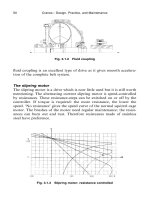
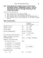
Section 3.6 shows how the power of the crane travelling motors should
be calculated. In Section 4.7 the calculation for the braking distance of
a crane was demonstrated. The influence of wind and storm can be
Cranes – Design, Practice, and Maintenance142
calculated, using the information in Section 1.5. Referring back to
Section 3.6 and resuming:
Weight of crane W
1
G1300 t (unloaded)
Influence of side wind FG(A · C ·
η
) · q
qG275 N͞m
2
F
w
G510 kN
– Under storm conditions, windforce: 11
qG583 N͞m
2
(windspeed 110 km͞h) F
S
G
583
275
· 510 G1080 kN
Available motorpower: ΣNG24 · 17G408 kW
When platebrakes are built-in in the
motors, or when open blockbrakes are
installed, the nominal breaking torque
is normally taken as: M
b
G1,8 · M
motor
Fig. 4.9.1 Storm pin (left) combined with stormbrake of the brake-shoe type
Brakes 143
Without taking the efficiency of the
gearboxes and the resistance of the
crane (3 kg ͞t) into account the braking
force through the driven wheels onto
the crane track is:
FG
1,8 · N
û
G
1,8 · 408
0,75
G979 kN
ûG45 m͞min G0,75 m͞sec
However, the crane tends to topple over due to this very heavy storm;
giving far more lower wheel loads on the leeside than on the windward
side. This means in fact that less braking force is available on the rails,
due to the decreased wheel loads on the windward side and – through
that – a decreased adhesion coefficient between wheel and rail. So: extra
storm brakes are needed. Take on landside and seaside one storm brake,
each for at least FG
1
4
· F
S
(kN).
Different types of storm brakes
Many types of storm brakes are available; among others there are:
1 The vertical pin type storm brake or stormpin
A vertical pin is put into an armoured pinhole next to the crane track.
Normally this is done by hand. Vertical stormpins give an absolutely
Fig. 4.9.2 Stormbrake of the rail clamp type
Cranes – Design, Practice, and Maintenance144
Fig. 4.9.3 Bubenzer rail clamp
safe system to prevent a crane drifting away in a storm or gale, but this
system has the disadvantage that the crane first has to be driven to the
position where the stormpin can be dropped into the stormpot. This is
the reinforced hole in the quay which is destined to take up the storm-
pin. These stormpots are normally located on a centre to centre distance
of approximately 50 m. In the worst case the crane has then to travel
some distance against the heavy wind toward the next stormpot which
is free. For this purpose the crane travelling motors must be strong
enough to cover at maximum motor torque the distance toward the
next stormpot.
2 The rail clamp type
With this type, hardened claws are pressed by springs against the sides
of the crane rail. Hydraulic cylinders or other active elements release
the claws from the rail sides, against the pressure of the springs.
3 The brake-shoe type
Here, a sturdy roll is fixed under the sill beam, directly above a rail
shoe which is covered on the underside with friction material and which
has a curved upperpart. A thrustor can lower the rail shoe onto the
rail; which is done when the crane is in the rest-position. If the strong
wind drives the crane aside, the roll touches the curved upperpart of
the rail shoe and presses the whole part of the crane weight that is