Cranes – Design, Practice, and Maintenance phần 7 doc
Bạn đang xem bản rút gọn của tài liệu. Xem và tải ngay bản đầy đủ của tài liệu tại đây (2.69 MB, 35 trang )
Cranes – Design, Practice, and Maintenance190
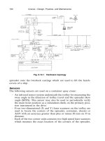
Fig. 6.10.1 Hardware topology
spreader onto the twistlock castings which are used to lift the hatch-
covers of a ship.
Sensors
The following sensors are used on a container quay crane:
– An infrared sensor system underneath the trolley for measuring the
sway angle in the direction of trolley travel and the spreader skew
angle (SPFS). This sensor may also be used to periodically verify
the main hoist position as a redundant check on the primary posi-
tion instrument in the drive.
– Four two-dimensional (X and Y) laser scanners on the trolley are
used to locate the corners of the spreader, container, chassis or
AGV with an accuracy greater than plus or minus 20 mm on 35 m
distance.
– Each of the two corner units contains two high speed laser scanners
which measure the exact location of the corners of the spreader,
Sagging, Rock and Roll, Positioning, and AEI 191
Fig. 6.10.2 Sensor arrangement on a trolley of a quay crane
container, chassis or AGV. One corner unit monitors the waterside
corner and the other the landside corner. The waterside corner unit
also includes the laser range finder which monitors the stack profile
and it also can peer into the hold of the ship.
A laser range finder is mounted underneath the trolley and is
used for stack profiling. It measures the distance without the use
of dedicated reflectors, and can achieve an accuracy of plus and
minus 10 mm at distances of up to 40 m (PSS).
– A laser range finder is mounted on the backreach of the crane for
an absolute position check of the trolley (APIS).
Learn cycles
First, the crane driver has to handle a container in a normal manner
manually, before the automatic mode is used. (Where anti-collision
devices are not used, Overhead Bridge Cranes (OHBCs) will not require
a learn cycle.)
Cranes – Design, Practice, and Maintenance192
Chassis Alignment Systems
Special camera-based vision systems may be employed to enhance the
procedure of aligning the transportation equipment (truck chassis,
bump-car, road chassis, etc.) under the crane. The vision-type imaging
system may use natural or artificial light sources or structured light
sources. Based on the image processing, the system indicates to the
truck chassis driver when the chassis or container is aligned with the
centreline of the crane. In addition, the same image processing is utilized
to automatically position the trolley over the chassis͞container and
automatically adjust the skew angle of the spreader to match that of
the chassis͞container. The system indicates to the crane operator when
the chassis position is outside the allowable skew angle which would
allow landing of the spreader. The crane is equipped with a visual sig-
nalling system that indicates to the truck driver when he is approaching
the correct position, when to stop, and when he has overshot the correct
alignment position.
Container Recognition Systems
Camera-based imaging systems are also employed to automatically
recognize the identification numbers printed on the sides and͞or ends
of the containers moved in the terminal. As the operator moves the
container to or from a vessel, cameras located at multiple locations on
the crane capture the ID number. The ID number is then passed over
a data network to a Yard Management System for processing. The
Yard Management System then issues orders or instructions to the yard
transportation equipment for proper dispatch of the container.
Yard Management Systems
The cranes may be supplied with wireless RF, optical fibre, or wave-
guide communication technology to interface with a Yard Management
System. The Yard Management System directs the movements of the
ground traffic, yard stacking crane, and the ship to shore cranes. The
sensors used on board the cranes for the various automation functions
discussed previously, are utilized to establish reports to the Yard Man-
agement System that include container size, container weight, container
pick-up coordinates, container drop-off coordinates, twistlock posi-
tions, etc.
Acknowledgement
Source of information for Section 6.10, Mr John T. Sholes, GE Toshiba
Automation Systems, Salem, Virginia, USA.
Sagging, Rock and Roll, Positioning, and AEI 193
Fig. 6.11.1 Definition of the geometry
6.11 The Stewart Platform Reeving
Patrick Stevedores Pty Inc. and the Australian Centre for Field Robot-
ics (ACFR) at the University of Sydney have recently developed a fully
patented reeving system for the hoist mechanisms of container cranes:
the Stewart Platform Reeving. Figure 6.11.1 shows the schematic lay-
out of the reeving, while Fig. 6.11.2 shows the 1:15 scale working model
of the installation.
The figures show the six hoisting wire ropes of the system. When the
six wire ropes are independently controlled, the six spatial degrees of
freedom can be used for complete control of the load by ‘microposition-
ing’. The reeving system then gives an excellent stiffness; trim, list, and
skew can then also be implemented in the system.
Cranes – Design, Practice, and Maintenance194
Fig. 6.11.2 The 1:15 scale working model
Stewart Platform reference:
D. Stewart A platform with six degrees of freedom. Proc. Instn Mech.
Engrs (London), Part I, 1965, 180(15), 371–386.
6.12 Checking the alignment of containers etc. with
Laser Scanners
Lase GmbH Industrielle Lasertechnik of Bremen, Germany developed
a fully patented Laser Scanning System with which the distances
between the spreader and a container, an AGV or trailer, etc., as well
as the relative position of these parts to each other can be measured.
When setting down a container on to – or taking a container from –
an AGV, the misalignment between the container and the AGV, as well
as the relative distances between spreader and container or AGV can
be controlled by using the Rotating Laser Scanners, in combination
with an Evaluation Unit, being a supervisory PC. If misalignments are
indicated, a crane driver or checker can correct the positioning.
Figure 6.12.1 gives an overview of the system; Fig. 6.12.2 shows the
measuring and positioning of the scanners at some 22 m above the quay
level; and Fig. 6.12.3 shows one of the ZPMC cranes, equipped with
this system.
Sagging, Rock and Roll, Positioning, and AEI 195
Fig. 6.12.1 Overview
Fig. 6.12.2 Positioning of the scanners
Cranes – Design, Practice, and Maintenance196
Fig. 6.12.3 Crane with laser scanners
The scanners have a cone-shaped scan which gives a cone diameter
of approximately 2,8 m over 20 m height. The cone-circle is scanned in
steps of 0,25 degrees.
6.13 Spreader Positioning System
Nelcon’s ‘1 over 4’ or 5-high Automated Stacking Cranes (ASCs) are
provided with a special ‘rope tower’ wire rope device for the hoisting
mechanism. Due to the way of reeving and the lay-out, this rope tower
is very stiff and permits the (fully automated) ASC to stack the con-
tainers accurately on top of each other.
However, under extreme conditions, e.g. a heavy storm, it is possible
that the required stacking accuracy cannot be met. For this purpose
BTG Engineering BV in Maasdam developed a fully patented Spreader
Positioning System, which controls the eventual sway or swing of the
spreader.
The spreader itself is therefore provided with hydraulic cylinders,
which are controlled by the PLC in the crane. On the spreader a box is
Sagging, Rock and Roll, Positioning, and AEI 197
Fig. 6.13.1 ASCs with Spreader Positioning Systems
Fig. 6.13.2 Box with PSD chip
Cranes – Design, Practice, and Maintenance198
mounted in which a LED system throws a beam of light towards a box
underneath the trolley. In this box a PSD chip (Position Sensitive
Device Chip) and a special lens are mounted. The beam of the LED
system is guided through the lens and hits the PSD chip. Through this
chip the PLC gets the various commands to activate the hydraulic cylin-
ders on the spreader, thus forcing the spreader with the underhanging
container to change its position.
6.14 Camera-Monitor Systems
Orlaco Products BV in Barneveld, The Netherlands, manufactures
camera systems which help crane drivers, truck drivers, etc. to overview
Fig. 6.14.1 The camera system
Sagging, Rock and Roll, Positioning, and AEI 199
Fig. 6.14.2 Overview of the system
the work area, the winches, etc. The camera of such a system is shock
and vibration proof and is extremely light sensitive. The system gives
the crane driver a much better feel for his work. As the lenses of the
cameras are heated, condensation and frost have no influence on the
camera.
This page intentionally left blank
Chapter 7
Construction and Calculation Methods
on Strength and Fatigue
7.1 Materials
(A) For steel constructions
Table 7.1.1 Table of corresponding former designations
Designation Equivalent former designation in
Acc. to
EN 10027-1 Acc. to
and ECISS Acc. to EN 10025: United Older
IC 10 EN10027-2 1990 Germany France Kingdom standards
S185 1.0035 Fe 310–0 St 33 A33 Fe 320
S235JR 1.0037 Fe 360 B St 37–2 E 24–2 Fe 360 B
S235JRG1 1.0036 Fe 360 BFU USt 37–2
S235JRG2 1.0038 Fe 360 BFN RSt 37–2 40 B
S235JO 1.0114 Fe 360 C St 37–3 U E 24–3 40 C Fe 360 C
S235J2G3 1.0116 Fe 360 D1 St 37–3 N E 24–4 40 D Fe 360 D
S235J2G4 1.0117 Fe 360 D2
S275JR 1.0044 Fe 430 B St 44–2 E 28–2 43 B Fe 430 B
S275J0 1.0143 Fe 430 C St 44–3 U E 28–3 43 C Fe 430 C
S275J2G3 1.0144 Fe 430 D1 St 44–3 N E 28–4 43 D Fe 430 D
S275JG4 1.0145 Fe 430 D2
S355JR 1.0045 Fe 510 B E 36–2 50 B Fe 510 B
S355J0 1.0553 Fe 510 C St 52–3 U E 36–3 50 C Fe 510 C
S355J2G3 1.0570 Fe 510 D1 St 52–3 N 50 D Fe 510 D
S355J2G4 1.0577 Fe 510 D2
S355K2G3 1.0595 Fe 510 DD1 E 36–4 50 DD
S355K2G4 1.0596 Fe 510 DD2 50 DD
E295 1.0050 Fe 490–2 St 50–2 A 50–2 Fe 480
E335 1.0060 Fe 590–2 St 60–2 A 60–2 Fe 580
E360 1.0070 Fe 690–2 St 70–2 A 70–2 A 690 Fe 690 B
Note:1.ENGEuropean norm (Euro Norm).
Cranes – Design, Practice, and Maintenance202
Table 7.1.2
Desoxi- Cin% for nominal M
n
Si P S N
dation Sub- plate thickness in %%%%%
Designation method group mm max. max. max. max. max.
Acc. to
EN10027–1 Acc. to
and EC͞SS EN
1C 10 10027–2 F16 H16 H40
S 185 1.0035 Choice BS ————— — — —
S235JR 1.0037 Choice BS 0,17 0,20 1,40 — 0,045 0,045 0,009
S235JRG1 1.0036 FU BS 0,17 0,20 — 1,40 — 0,045 0,045 0,007
S235JRG2 1.0038 FN BS 0,17 0,17 0,20 1,40 — 0,045 0,045 0,009
S235JO 1.0114 FN QS 0,17 0,17 0,17 1,40 — 0,040 0,040 0,009
S235J2G3 1.0116 FF QS 0,17 0,17 0,17 1,40 — 0,035 0,035 —
S235J2G4 1.0117 FF QS 0,17 0,17 0,17 1,40 — 0,035 0,035 —
S275JR 1.0044 FN BS 0,21 0,21 0,22 1,50 — 0,045 0,045 0,009
S275JO 1.0143 FN QS 0,18 0,18 0,18 1,50 — 0,040 0,040 0,009
S275J2G3 1.0144 FF QS 0,18 0,18 0,18 1,50 — 0,035 0,035 —
S275J2G4 1.0145 FF QS 0,18 0,18 0,18 1,50 — 0,035 0,035 —
S355JR 1.0045 FN BS 0,24 0,24 0,24 1,60 0,55 0,045 0,045 0,009
S355JO 1.0553 FN QS 0,20 0,20 0,22 1,60 0,55 0,040 0,040 0,009
S355J2G3 1.0570 FF QS 0,20 0,20 0,22 1,60 0,55 0,035 0,035 —
S355J2G4 1.0577 FF QS 0,20 0,20 0,22 1,60 0,55 0,035 0,035 —
S355K2G3 1.0595 FF QS 0,20 0,20 0,22 1,60 0,55 0,035 0,035 —
S355K2G4 1.0596 FF QS 0,20 0,20 0,22 1,60 0,55 0,035 0,035 —
E295 1.0050 FN BS —————0,045 0,045 0,009
E335 1.0060 FN BS —————0,045 0,045 0,009
E360 1.0070 FN BS —————0,045 0,045 0,009
Notes:BSGsteel for general use; QSGquality steel.
Construction and Calculation Methods 203
Pipes
52 N pipes are supplied in a normalized condition. The normalizing
temperature is approximately 920°C. After the required temperature
has been attained over the entire cross section, the pipes are cooled off
in the air. The stress relieving temperature is 530–580°C.
The 0,2 yield strength is min. 340 N͞mm
2
; the tensile strength min.
460 N͞mm
2
, the elongation is 20 percent.
(B) For mechanisms
See also Section 7.6.C; Fatigue in mechanism components as shafts;
Table B1 for allowable stresses.
Materials
Fe 360
Fe 510 CK 35
CK 45
CK 60
42 Cr Mo
4
34 Cr Ni Mo
6
7.2 Welding
Welding is one of the most important activities in the manufacture of
cranes and similar equipment. A great deal of this is hand-welding; a
highly skilled and precise job carried out by an experienced welder. As
much as possible is done with automatic welding machines. These give
a higher output and a more homogeneous weld. Widely used methods
include the following.
Manual Metal Arc or MMA-welding
MMA-welding or welding by hand is mostly used for welding steel
plates, angles, etc. of material quality Fe 360 or Fe 510 (S355).
The welding has to be done with basic electrodes of a high output
type. The skill of the welder is most important to achieve good quality
welds.
Cranes – Design, Practice, and Maintenance204
Fig. 7.2.1 The welding of a big box girder
MIG-welding
This is a gas-shielded Metal Arc welding, which is carried out using a
continuous wire electrode. The continuous wire electrode is fed auto-
matically into the welding gun, where the shielding gas is added to the
welding process. The weld is then shielded by a stream of Metal Inert
Gas (MIG), which is a mix of CO
2
and Argon.
Construction and Calculation Methods 205
Fig. 7.2.2 Welded pipe constructions
Cranes – Design, Practice, and Maintenance206
MAG-welding
Following the same process as given under MIG-welding a Metal
Active Gas (MAG) is where 100 percent CO
2
is used for the shielding.
The MAG process gives a rather deeper penetration than the MIG
process.
Submerged arc welding or SAW-welding
In submerged arc welding an arc is maintained between the work and
the end of a cored wire electrode, which is continuously fed into the arc
by motor driven feed rolls. The arc is invisible and operates beneath a
layer of granular flux, some of which melts to provide a protective slag
cover over the weld pool.
There are hand-held welding guns available, however submerged arc
welding is principally done with fully automatic equipment. It is par-
ticularly suitable for long straight joints of a very high quality, which
are laid in a flat position.
Flux Core Arc-welding
This type of automatic welding can, among others, be used in the weld-
ing of pipes and tubes. The welding wire which gives slag, is of the
Rutyl type and includes a small percentage of Nickel, giving a fine weld-
ing result.
Dangers: the prevention of problems
Cracks, which are of course dangerous, can occur in welds, and there-
fore the welds have to be controlled carefully. This can be done by
visual, ultrasonic or X-ray inspection and by methods in which pene-
trating liquids with a magnetic control system for cracks is used.
It is always most important to avoid H
2
(Hydrogen). The carbon
content of the materials must also be kept as low as possible.
The shrinkage of a construction during the welding process must be
continuously controlled, and extra tensions in the construction due to
shrinkage must be avoided to prevent cracks or even break-downs.
The cooling off of the weld and its surroundings must be kept within
allowable limits. It is, therefore, necessary to preheat thicker construc-
tions before welding in order to prevent the weld cooling-off too quickly
in relation to its surroundings.
Welders
Welders must be well trained for their job. Their qualification goes from
1G up to 6GR.
Construction and Calculation Methods 207
Possible detrimental phenomena resulting from welding
Among others, these may be:
– Hydrogen cracks;
– reduction of toughness;
– solidification cracking;
– lamellar tearing – reduction of the sensitivity to lamellar tearing
can be achieved by connecting all layers of the plate, see Fig. 7.2.3;
– stress relief heat treatment cracks;
– differences in chemical position, grain size and stress levels between
the weld and the parent material may lead to different corrosion
rates. In most cases the weld and heat affected zones are attacked
preferentially;
– stress corrosion cracking.
Fig. 7.2.3 Reduction of the sensitivity to lamellar tearing
Fig. 7.2.4 Submerged arc welding
Cranes – Design, Practice, and Maintenance208
7.3 Bolts
The types of bolts now widely used are ‘High strength’ types 8.8 and
10.9. These marks are shown on the head of the bolt and on the nut.
8.8 means: min. tensile strength: 80 kN͞cm
2
min. yield strength: 8B8G64 kN͞cm
2
10.9 means: min. tensile strength: 100 kN͞cm
2
min. yield strength: 10B9G90 kN͞cm
2
The plates which are bolted together must be painted with special paint
on those places where the bolts are used. Sometimes injection bolts are
Table 7.3.1 Bolt characteristics
Nos. of Allowed
Tensile Tightening Prestressing friction Transmissible tensile
Bolt section moment force surfaces shear force force
8.8 M 10.9 M 8.8 P 10.9 P
cm
2
kN cm kN cm kN kN 8.8 10.9 8.8 10.9
M 16 1,57 23 33 80 113 1 14 20 30 43
22840
M 20 2,45 45 64 125 176 1 22 31 66 92
24563
M 24 3,53 78 110 181 254 1 32 45 95 133
26491
M 30 5,61 155 218 287 404 1 51 72 150 212
2 102 144
Fig. 7.3.1 Bolted connection
Construction and Calculation Methods 209
Fig. 7.3.2 Flange plates with injection bolts
Fig. 7.3.3 A bolted A-frame construction
Cranes – Design, Practice, and Maintenance210
used in heavy construction in order to eliminate the free space which
pops up when the holes in the connection plates do not mate to each
other properly.
7.4 Construction of box and lattice girders, etc.
When riveting used to be the main method to connect materials, all
cranes and unloaders consisted of lattice constructions. Since welding
replaced riveting, box constructions have become more and more popu-
lar. Most cranes and unloaders are built up from box-type elements.
However, it must be stated that welded lattice girders often can give
excellent solutions for girders, booms, jibs, towercranes, etc.
Fig. 7.4.1 Heavy load erection crane
Construction and Calculation Methods 211
Fig. 7.4.2 Riveted construction
Fig. 7.4.3 Bolted construction
Cranes – Design, Practice, and Maintenance212
Fig. 7.4.4 Welded construction
Fig. 7.4.5 Lattice girder construction
Construction and Calculation Methods 213
Fig. 7.4.6 Flange plate construction
Fig. 7.4.7 von Karman strips
Cranes – Design, Practice, and Maintenance214
Typical girder constructions
Figures 7.4.8 and 7.4.9 give examples of single and double box girders
and lattice girder constructions.
Fig. 7.4.8 Double box girder construction
Fig. 7.4.9 Single box and lattice girder construction