DESIGN OF MACHINERYAN INTRODUCTION TO THE SYNTHESIS AND ANALYSIS OF MECHANISMS AND MACHINES phần 2 potx
Bạn đang xem bản rút gọn của tài liệu. Xem và tải ngay bản đầy đủ của tài liệu tại đây (4.11 MB, 93 trang )
multiple orthographic views of the design, and investigate its motions by drawing arcs,
showing multiple positions, and using transparent, movable overlays. Computer-aided
drafting (CAD) systems can speed this process to some degree, but you will probably
find that the quickest way to get a sense of the quality of your linkage design is to model
it, to scale, in cardboard or drafting Mylar® and see the motions directly.
Other tools are available in the form of computer programs such as FOURBAR,FIVE-
BAR, SIXBAR,SLIDER,DYNACAM,ENGINE, and MATRIX(all included with this text),
some of which do synthesis, but these are mainly analysis tools. They can analyze a trial
mechanism solution so rapidly that their dynamic graphical output gives almost instan-
taneous visual feedback on the quality of the design. Commercially available programs
such as Working Model* also allow rapid analysis of a proposed mechanical design. The
process then becomes one of qualitative design by successive analysis which is really
an iteration between synthesis and analysis. Very many trial solutions can be examined
in a short time using these Computer-aided engineering (CAE) tools. We will develop
the mathematical solutions used in these programs in subsequent chapters in order to pro-
vide the proper foundation for understanding their operation. But, if you want to try
these programs to reinforce some of the concepts in these early chapters, you may do so.
Appendix A is a manual for the use of these programs, and it can be read at any time.
Reference will be made to program features which are germane to topics in each chap-
ter, as they are introduced. Data files for input to these computer programs are also pro-
vided on disk for example problems and figures in these chapters. The data file names
are noted near the figure or example. The student is encouraged to input these sample files
to the programs in order to observe more dynamic examples than the printed page can pro-
vide. These examples can be run by merely accepting the defaults provided for all inputs.
TYPE SYNTHESIS refers to the definition of the proper type of mechanism best suit-
ed to the problem and is a form of qualitative synthesis.t This is perhaps the most diffi-
cult task for the student as it requires some experience and knowledge of the various
types of mechanisms which exist and which also may be feasible from a performance
and manufacturing standpoint. As an example, assume that the task is to design a device
to track the straight-line motion of a part on a conveyor belt and spray it with a chemical
coating as it passes by. This has to be done at high, constant speed, with good accuracy
and repeatability, and it must be reliable. Moreover, the solution must be inexpensive.
Unless you have had the opportunity to see a wide variety of mechanical equipment, you
might not be aware that this task could conceivably be accomplished by any of the fol-
lowing devices:
- A straight-line linkage
- A carn and follower
- An air cylinder
- A hydraulic cylinder
- A robot
- A solenoid
Each of these solutions, while possible, may not be optimal or even practical. More
detail needs to be known about the problem to make that judgment, and that detail will
come from the research phase of the design process. The straight-line linkage may prove
to be too large and to have undesirable accelerations; the cam and follower will be ex-
pensive, though accurate and repeatable. The air cylinder itself is inexpensive but is
noisy and unreliable. The hydraulic cylinder is more expensive, as is the robot. The so-
*
Thestudentversionof
Working Model isincluded
onCD-ROMwiththisbook.
Theprofessionalversionis
availablefromKnowledge
RevolutionInc.,SanMateo
CA94402, (800) 766-6615
t
Agooddiscussionoftype
synthesisandanextensive
bibliographyonthetopic
canbefoundin
Olson,D.G.,etal.(1985).
"ASystematicProcedurefor
TypeSynthesisof
MechanismswithLiterature
Review."Mechanism and
Machine Theory, 20(4), pp.
285-295.
* Available from
Knowledge Revolution Inc.,
San Mateo CA 94402,
(800) 766-6615.
lenoid, while cheap, has high impact loads and high impact velocity. So, you can see
that the choice of device type can have a large effect on the quality of the design. A poor
choice at the type synthesis stage can create insoluble problems later on. The design
might have to be scrapped after completion, at great expense. Design is essentially an
exercise in trade-offs. Each proposed type of solution in this example has good and bad
points. Seldom will there be a clear-cut, obvious solution to a real engineering design
problem. It will be your job as a design engineer to balance these conflicting features
and find a solution which gives the best trade-off of functionality against cost, reliabili-
ty, and all other factors of interest. Remember, an engineer can do, with one dollar, what
any fool can do for ten dollars. Cost is always an important constraint in engineering
design.
QUANTITATIVESYNTHESIS,OR ANALYTICALSYNTHESIS means the generation
of one or more solutions of a particular type which you know to be suitable to the prob-
lem, and more importantly, one for which there is a synthesis algorithm defined. As the
name suggests, this type of solution can be quantified, as some set of equations exists
which will give a numerical answer. Whether that answer is a good or suitable one is
still a matter for the judgment of the designer and requires analysis and iteration to opti-
mize the design. Often the available equations are fewer than the number of potential
variables, in which case you must assume some reasonable values for enough unknowns
to reduce the remaining set to the number of available equations. Thus some qualitative
judgment enters into the synthesis in this case as well. Except for very simple cases, a
CAE tool is needed to do quantitative synthesis. One example of such a tool is the pro-
gram LlNCAGES,* by A. Erdman et aI., of the University of Minnesota [1] which solves
the three-position and four-position linkage synthesis problems. The computer programs
provided with this text also allow you to do three-position analytical synthesis and gen-
eral linkage design by successive analysis. The fast computation of these programs al-
lows one to analyze the performance of many trial mechanism designs in a short time
and promotes rapid iteration to a better solution.
DIMENSIONALSYNTHESIS of a linkage is the determination of the proportions
(lengths) of the links necessary to accomplish the desired motions and can be a form of
quantitative synthesis if an algorithm is defined for the particular problem, but can also
be a form of qualitative synthesis if there are more variables than equations. The latter
situation is more common for linkages. (Dimensional synthesis of cams is quantitative.)
Dimensional synthesis assumes that, through type synthesis, you have already deter-
mined that a linkage (or a cam) is the most appropriate solution to the problem. This
chapter discusses graphical dimensional synthesis of linkages in detail. Chapter 5 pre-
sents methods of analytical linkage synthesis, and Chapter 8 presents cam synthesis.
3.2 FUNCTION, PATH, AND MOTION GENERATION
FUNCTIONGENERATION is defined as the correlation of an input motion with an out-
put motion in a mechanism. A function generator is conceptually a "black box" which
delivers some predictable output in response to a known input. Historically, before the
advent of electronic computers, mechanical function generators found wide application
in artillery rangefinders and shipboard gun aiming systems, and many other tasks. They
are, in fact, mechanical analog computers. The development of inexpensive digital
electronic microcomputers for control systems coupled with the availability of compact
servo and stepper motors has reduced the demand for these mechanical function genera-
tor linkage devices. Many such applications can now be served more economically and
efficiently with electromechanical devices.
*
Moreover, the computer-controlled electro-
mechanical function generator is programmable, allowing rapid modification of the func-
tion generated as demands change. For this reason, while presenting some simple ex-
amples in this chapter and a general, analytical design method in Chapter 5, we will not
emphasize mechanical linkage function generators in this text. Note however that the
cam-follower system, discussed extensively in Chapter 8, is in fact a form of mechani-
cal function generator, and it is typically capable of higher force and power levels per
dollar than electromechanical systems.
PATH GENERATION
is defined as the control of a point in the plane such that it
follows some prescribed path. This is typically accomplished with at least four bars,
wherein a point on the coupler traces the desired path. Specific examples are presented
in the section on coupler curves below. Note that no attempt is made in path generation
to control the orientation of the link which contains the point of interest. However, it is
common for the timing of the arrival of the point at particular locations along the path to
be defined. This case is called path generation with prescribed timing and is analogous
to function generation in that a particular output function is specified. Analytical path
and function generation will be dealt with in Chapter 5.
MOTION GENERATION
is defined as the control of a line in the plane such that it
assumes some prescribed set of sequential positions. Here orientation of the link con-
taining the line is important. This is a more general problem than path generation, and
in fact, path generation is a subset of motion generation. An example of a motion gener-
ation problem is the control of the "bucket" on a bulldozer. The bucket must assume a
set of positions to dig, pick up, and dump the excavated earth. Conceptually, the motion
of a line, painted on the side of the bucket, must be made to assume the desired positions.
A linkage is the usual solution.
PLANARMECHANISMSVERSUSSPATIALMECHANISMS
The above discussion of
controlled movement has assumed that the motions desired are planar (2-D). We live in
a three-dimensional world, however, and our mechanisms must function in that world.
Spatial mechanisms are 3-D devices. Their design and analysis is much more complex
than that of planar mechanisms, which are 2-D devices. The study of spatial mecha-
nisms is beyond the scope of this introductory text. Some references for further study
are in the bibliography to this chapter. However, the study of planar mechanisms is not
as practically limiting as it might first appear since many devices in three dimensions are
constructed of multiple sets of 2-D devices coupled together. An example is any folding
chair. It will have some sort of linkage in the left side plane which allows folding. There
will be an identical linkage on the right side of the chair. These two
XY
planar linkages
will be connected by some structure along the Z direction, which ties the two planar link-
ages into a 3-D assembly. Many real mechanisms are arranged in this way, as duplicate
planar linkages, displaced in the Z direction in parallel planes and rigidly connected.
When you open the hood of a car, take note of the hood hinge mechanism. It will be du-
plicated on each side of the car. The hood and the car body tie the two planar linkages
together into a 3-D assembly. Look and you will see many other such examples of as-
semblies of planar linkages into 3-D configurations. So, the 2-D techniques of synthesis
and analysis presented here will prove to be of practical value in designing in 3-D as well.
*
It is worth noting that
the day is long past when a
mechanical engineer can
be content to remain
ignorant of electronics and
electromechanics.
Virtually all modem
machines are controlled by
electronic devices.
Mechanical engineers must
understand their operation.
3.3 LIMITINGCONDITIONS
The manual, graphical, dimensional synthesis techniques presented in this chapter and
the computerizable, analytical synthesis techniques presented in Chapter 5 are reason-
ably rapid means to obtain a trial solution to a motion control problem. Once a potential
solution is found, it must be evaluated for its quality. There are many criteria which may
be applied. In later chapters, we will explore the analysis of these mechanisms in detail.
However, one does not want to expend a great deal of time analyzing, in great detail, a
design which can be shown to be inadequate by some simple and quick evaluations.
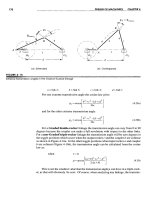
TOGGLE
One important test can be applied within the synthesis procedures de-
scribed below. You need to check that the linkage can in fact reach all of the specified
design positions without encountering a limit or toggle position, also called a station-
ary configuration. Linkage synthesis procedures often only provide that the particular
positions specified will be obtained. They say nothing about the linkage's behavior be-
tween those positions. Figure 3-1a shows a non-Grashof fourbar linkage in an arbitrary
position CD (dashed lines), and also in its two toggle positions, CIDI (solid black lines)
and C2D2 (solid red lines). The toggle positions are determined by the colinearity of two
of the moving links. A fourbar double- or triple-rocker mechanism will have at least two
of these toggle positions in which the linkage assumes a triangular configuration. When
in a triangular (toggle) position, it will not allow further input motion in one direction
from one of its rocker links (either of link 2 from position C
1
Dl
or link 4 from position
C2D2)' The other rocker will then have to be driven to get the linkage out of toggle. A
Grashof fourbar crank-rocker linkage will also assume two toggle positions as shown in
Figure 3-1b, when the shortest link (crank
02C)
is colinear with the coupler CD (link 3),
either extended colinear (02C2D2) or overlapping colinear (02C 1Dl)' It cannot be back
driven from the rocker 04D (link 4) through these colinear positions, but when the crank
02C (link 2) is driven, it will carry through both toggles because it is Grashof. Note that
these toggle positions also define the limits of motion of the driven rocker (link 4), at
which its angular velocity will go through zero. Use program FOURBARto read the data
files F03-01AABR and F03-lbAbr and animate these examples.
After synthesizing a double- or triple-rocker solution to a multiposition (motion
generation) problem, you must check for the presence of toggle positions between your
design positions. An easy way to do this is with a cardboard model of the linkage de-
sign. A CAE tool such as FOURBARor Working Model will also check for this problem.
It is important to realize that a toggle condition is only undesirable if it is preventing your
linkage from getting from one desired position to the other.
In
other circumstances the
toggle is very useful. It can provide a self-locking feature when a linkage is moved
slightly beyond the toggle position and against a fixed stop. Any attempt to reverse the
motion of the linkage then causes it merely to jam harder against the stop. It must be
manually pulled "over center," out of toggle, before the linkage will move. You have
encountered many examples of this application, as in card table or ironing board leg link-
ages and also pickup truck or station wagon tailgate linkages. An example of such a tog-
gle linkage is shown in Figure 3-2. It happens to be a special-case Grashof linkage in
the deltoid configuration (see also Figure 2-17d, p. 49), which provides a locking toggle
position when open, and folds on top of itself when closed, to save space. We will ana-
lyze the toggle condition in more detail in a later chapter.
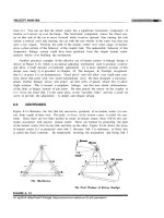
TRANSMISSION ANGLE Another useful test that can be very quickly applied to a
linkage design to judge its quality is the measurement of its transmission angle. This can
be done analytically, graphically on the drawing board, or with the cardboard model for
a rough approximation. (Extend the links beyond the pivot to measure the angle.) The
transmission angle 11is shown in Figure 3-3a and is defined as the angle between the
output link and the coupler.
*
It is usually taken as the absolute value of the acute angle
of the pair of angles at the intersection of the two links and varies continuously from some
minimum to some maximum value as the linkage goes through its range of motion. It is
a measure of the quality of force and velocity transmission at the joint.
t
Note in Figure
3-2 that the linkage cannot be moved from the open position shown by any force applied
to the tailgate, link 2, since the transmission angle is then between links 3 and 4 and is
zero at that position. But a force applied to link 4 as the input link will move it. The trans-
mission angle is now between links 3 and 2 and is 45 degrees.
* Alt, [2] who defined the
transmission angle,
recommended keeping
Ilmin
>
40°. But it can be
atgued that at higher speeds,
the momentum of the
moving elements and/or the
addition of a flywheel will
carry a mechanism through
locations of poor transmis-
sion angle. The most
common example is the
back -driven slider crank (as
used in internal combustion
engines) which has
11
=
0 twice per revolution.
Also, the transmission angle
is only critical in a foucbar
linkage when the rocker is
the output link on which the
working load impinges. If
the working load is taken by
the coupler rather than by
the rocker, then minimum
transmission angles less than
40° may be viable. A more
definitive way to qualify a
mechanism's dynamic
function is to compute the
variation in its required
driving torque. Driving
torque and flywheels are
addressed in Chapter II. A
joint force index
(IA)
can
also be calculated. (See
footnotet on p. 81.)
Figure 3-3b shows a torque T2 applied to link 2. Even before any motion occurs,
this causes a static, colinear force
F34
to be applied by link 3 to link 4 at point
D.
Its
radial and tangential components
F{4
and
Fj4
are resolved parallel and perpendicular to
link 4, respectively. Ideally, we would like all of the force F 34 to go into producing out-
put torque T4 on link 4. However, only the tangential component creates torque on link
4. The radial component
F{4
provides only tension or compression in link 4. This radial
component only increases pivot friction and does not contribute to the output torque.
Therefore, the optimum value for the transmission angle is 90°. When 11is less than
45° the radial component will be larger than the tangential component. Most machine
designers try to keep the minimum transmission angle above about 40° to promote
smooth running and good force transmission. However, if in your particular design there
will be little or no external force or torque applied to link 4, you may be able to get away
with even lower values of 11.
*
The transmission angle provides one means to judge the
quality of a newly synthesized linkage. If it is unsatisfactory, you can iterate through the
synthesis procedure to improve the design. We will investigate the transmission angle
in more detail in later chapters.
3.4 DIMENSIONAL SYNTHESIS
Dimensional synthesis of a linkage is the determination of the proportions (lengths) of
the links necessary to accomplish the desired motions. This section assumes that,
through type synthesis, you have determined that a linkage is the most appropriate solu-
tion to the problem. Many techniques exist to accomplish this task of dimensional syn-
thesis of a fourbar linkage. The simplest and quickest methods are graphical. These
work well for up to three design positions. Beyond that number, a numerical, analytical
synthesis approach as described in Chapter 5, using a computer, is usually necessary.
Note that the principles used in these graphical synthesis techniques are simply those
of euclidean geometry. The rules for bisection oflines and angles, properties of parallel _
and perpendicular lines, and definitions of arcs, etc., are all that are needed to generate
these linkages. Compass, protractor, and rule are the only tools needed for graphical
linkage synthesis. Refer to any introductory (high school) text on geometry if your geo-
metric theorems are rusty.
Two-Position Synthesis
Two-position synthesis subdivides into two categories: rocker output (pure rotation)
and coupler output (complex motion). Rocker output is most suitable for situations in
which a Grashof crank-rocker is desired and is, in fact, a trivial case of/unction genera-
tion in which the output function is defined as two discrete angular positions of the rock-
er. Coupler output is more general and is a simple case of motion generation in which
two positions of a line in the plane are defined as the output. This solution will frequent-
ly lead to a triple-rocker. However, the fourbar triple-rocker can be motor driven by the
addition of a dyad (twobar chain), which makes the final result a Watt's sixbar contain-
ing a Grashof fourbar subchain. We will now explore the synthesis of each of these
types of solution for the two-position problem.
Problem:
Design a fourbar Grashof crank-rocker to give 45° of rocker rotation with equal
time forward and back, from a constant speed motor input.
Solution:
(see Figure 3-4)
I
Draw the output link
O,V]
in both extreme positions, B[ and B2 in any convenient location,
such that the desired angle of motion
84
is subtended.
2 Draw the chord B[B2 and extend it in any convenient direction.
3 Select a convenient point O
2
on line B[B2 extended.
4 Bisect line segment B [B2 , and draw a circle of that radius about 02.
5 Label the two intersections of the circle and B[B2 extended, A[ and A2.
6
Measure the length of the coupler asA [ to B[ or A2 to B2.
7 Measure ground length I, crank length 2, and rocker length 4.
8 Find the Grashof condition. If non-Grashof, redo steps 3 to 8 with O
2
further from 04.
9 Make a cardboard model of the linkage and articulate it to check its function and its trans-
mission angles.
10
You can input the file F03-04.4br to program FOURBARto see this example come alive.
Note several things about this synthesis process. We started with the output end of
the system, as it was the only aspect defined in the problem statement. We had to make
many quite arbitrary decisions and assumptions to proceed because there were many
more variables than we could have provided "equations" for. We.are frequently forced
to make "free choices" of "a convenient angle or length." These free choices are actual-
ly definitions of design parameters. A poor choice will lead to a poor design. Thus these
are qualitative synthesis approaches and require an iterative process, even for this sim-
ple an example. The first solution you reach will probably not be satisfactory, and sev-
eral attempts (iterations) should be expected to be necessary. As you gain more experi-
ence in designing kinematic solutions you will be able to make better choices for these
design parameters with fewer iterations. The value of makiug a simple model of your
design cannot be overstressed! You will get the most insight into your design's quality
for the least effort by making, articulating, and studying the model. These general ob-
servations will hold for most of the linkage synthesis examples presented.
Coupler Output - Two Positionswith Complex Displacement. (Motion Generation)
Problem: Design a fourbar linkage to move the link CD shown from position
C)D)
to
C2D2
(with moving pivots at C and
D).
SolutIon: (see Figure 3-6)
1 Draw the link CD in its two desired positions, C)D) and
C2D2,
in the plane as shown.
2 Draw construction lines from point C) to C2 and from point D) to
D2.
3 Bisect line C) C2 and line
D)D2
and extend the perpendicular bisectors in convenient direc-
tions. The rotopole will not be used in this solution.
had nearly the same problem statement as Example 3-2, but the solution is quite differ-
ent. Thus a link can also be moved to any two positions in the plane as the coupler of a
fourbar linkage, rather than as the rocker. However, to limit its motions to those two cou-
pler positions as extrema, two additional links are necessary. These additional links can
be designed by the method shown in Example 3-4 and Figure 3-7.
er
stage for our existing fourbar. This results in a sixbar Watt's mechanism whose first
stage is Grashof as shown in Figure 3-7b. Thus we can drive this with a motor on link 6.
Note also that we can locate the motor center
06
anywhere in the plane by judicious
choice of point B
1
on link 2. If we had put B
1
below center
02,
the motor would be to
the right of links 2, 3, and 4 as shown in Figure 3-7c. There is an infinity of driver dyads
possible which will drive any double-rocker assemblage of links. Input the files
RB-07b.6br and F03-07c.6br to program SIXBAR to see Example 3-4 in motion for these
two solutions.
Three-Position Synthesis with Specified Moving Pivots
Three-position synthesis allows the definition of three positions of a line in the plane
and will create a fourbar linkage configuration to move it to each of those positions. This
is a motion generation problem. The synthesis technique is a logical extension of the
method used in Example 3-3 for two-position synthesis with coupler output. The result-
ing linkage may be of any Grashof condition and will usually require the addition of a
dyad to control and limit its motion to the positions of interest. Compass, protractor, and
rule are the only tools needed in this graphical method.
Note that while a solution is usually obtainable for this case, it is possible that you
may not be able to move the linkage continuously from one position to the next without
disassembling the links and reassembling them to get them past a limiting position. That
will obviously be unsatisfactory. In the particular solution presented in Figure 3-8, note
that links 3 and 4 are in toggle at position one, and links 2 and 3 are in toggle at position
three. In this case we will have to drive link 3 with a driver dyad, since any attempt to
drive either link 2 or link 4 will fail at the toggle positions. No amount of torque applied
to link 2 at position C1 will move link 4 away from point
Db
and driving link 4 will not
move link 2 away from position C3. Input the file F03-08.4br to program FOURBARto
see Example 3-5.
Three-Position Synthesis with Alternate Moving Pivots
Another potential problem is the possibility of an undesirable location of the fixed piv-
ots
02
and
04
with respect to your packaging constraints. For example, if the fixed piv-
ot for a windshield wiper linkage design ends up in the middle of the windshield, you
may want to redesign it. Example 3-6 shows a way to obtain an alternate configuration
for the same three-position motion as in Example 3-5. And, the method shown in Exam-
ple 3-8 (ahead on p. 95) allows you to specify the location of the fixed pivots in advance
and then find the locations of the moving pivots on link 3 that are compatible with those
fixed pivots.
Note that the shift of the attachment points on link 3 from CD to
EF
has resulted in
a shift of the locations of fixed pivots 02 and 04 as well. Thus they may now be in more
favorable locations than they were in Example 3-5. It is important to understand that any
two points on link 3, such as E and F, can serve to fully define that link as a rigid body,
and that there is an infinity of such sets of points to choose from. While points C and D
have some particular location in the plane which is defined by the linkage's function,
points
E
and
F
can be anywhere on link 3, thus creating an infinity of solutions to this
problem.
The solution in Figure 3-9 is different from that of Figure 3-8 in several respects. It
avoids the toggle positions and thus can be driven by a dyad acting on one of the rock-
ers, as shown in Figure 3-9c, and the transmission angles are better. However, the tog-
gle positions of Figure 3-8 might actually be of value if a self-locking feature were de-
sired. Recognize that both of these solutions are to the same problem, and the solution
Line CD moves through the same three positions with both designs. There is an infinity
of other solutions to this problem waiting to be found as well. Input the file F03-09c.6br
to program
SrXBAR
to see Example 3-6.
Three-Position Synthesis with Specified Fixed Pivots
Even though one can probably find an acceptable solution to the three-position problem
by the methods described in the two preceding examples, it can be seen that the designer
will have little direct control over the location of the fixed pivots since they are one of
the results of the synthesis process. It is common for the designer to have some con-
straints on acceptable locations of the fixed pivots, since they will be limited to locations
at which the ground plane of the package is accessible. It would be preferable if we could
define the fixed pivot locations, as well as the three positions of the moving link, and then
synthesize the appropriate attachment points, E and F, to the moving link to satisfy these
more realistic constraints. The principle of inversion can be applied to this problem.
Examples 3-5 and 3-6 showed how to find the required fixed pivots for three chosen
positions of the moving pivots. Inverting this problem allows specification of the fixed
pivot locations and determination of the required moving pivots for those locations. The
first step is to find the three positions of the ground plane which correspond to the three
desired coupler positions. This is done by inverting the linkage
*
as shown in Figure
3-10 and Example 3-7.
By inverting the original problem, we have reduced it to a more tractable form which
allows a direct solution by the general method of three-position synthesis from Exam-
ples 3-5 and 3-6.
Position Synthesis for More Than Three Positions
It should be obvious that the more constraints we impose on these synthesis problems,
the more complicated the task becomes to find a solution. When we define more than
three positions of the output link, the difficulty increases substantially.
FOUR-POSITION SYNTHESIS does not lend itself as well to manual graphical so-
lutions, though Hall
[3]
does present one approach. Probably the best approach is that
used by Sandor and Erdman
[4]
and others, which is a quantitative synthesis method and
requires a computer to execute it. Briefly, a set of simultaneous vector equations is writ-
ten to represent the desired four positions of the entire linkage. These are then solved
after some free choices of variable values are made by the designer. The computer pro-
gram LINCAGES [1] by Erdman et aI., and the program KINSYN [5]by Kaufman, both pro-
vide a convenient and user-friendly computer graphics based means to make the neces-
sary design choices to solve the four-position problem. See Chapter 5 for further discussion.
3.5 QUICK-RETURN MECHANISMS
Many machine design applications have a need for a difference in average velocity be-
tween their "forward" and "return" strokes. Typically some external work is being done
by the linkage on the forward stroke, and the return stroke needs to be accomplished as
rapidly as possible so that a maximum of time will be available for the working stroke.
Many arrangements of links will provide this feature. The only problem is to synthesize
the right one!
Fourbar Quick-Return
The linkage synthesized in Example 3-1 is perhaps the simplest example of a fourbar
linkage design problem (see Figure 3-4, p. 84, and program FOURBAR disk file
F03-04.4br). It is a crank-rocker which gives two positions of the rocker with equal time
for the forward stroke and the return stroke. This is called a non-quick-retum linkage,
and it is a special case of the more general quick-return case. The reason for its non
quick-return state is the positioning of the crank center
02
on the chord BIB2 extended.
This results in equal angles of 180 degrees being swept out by the crank as it drives the
rocker from one extreme (toggle position) to the other. If the crank is rotating at con-
stant angular velocity, as it will tend to when motor driven, then each 180 degree sweep,
forward and back, will take the same time interval. Try this with your cardboard model
from Example 3-1 by rotating the crank at uniform velocity and observing the rocker
motion and velocity.
transmission angles become poor, and a more complex linkage is needed. Input the file
F03-12.4br to program FOURBARto see Example 3-9.
Sixbar Quick-Return
Larger time ratios, up to about 1:2, can be obtained by designing a sixbar linkage. The
strategy here is to first design a fourbar drag link mechanism which has the desired time
ratio between its driver crank and its driven or "dragged" crank, and then add a dyad
(twobar) output stage, driven by the dragged crank. This dyad can be arranged to have
either a rocker or a translating slider as the output link. First the drag link fourbar will
be synthesized; then the dyad will be added.