Dust Explosions in the Process Industries Second Edition phần 9 ppt
Bạn đang xem bản rút gọn của tài liệu. Xem và tải ngay bản đầy đủ của tài liệu tại đây (3.98 MB, 66 trang )
Assessment
of
ignitability
5
19
Figure
7.36
ignition energy
of
dust clouds
Three different electric spark discharge circuits used for determining the minimum
ing the discharge with the dust cloud, may be appreciable. Sophisticated elements such as
thyrathrons have been employed to solve this problem.
However, synchronization
of
spark and dust cloud can also be accomplished by
incorporating a third, auxiliary spark electrode in the spark gap configuration. By
discharging just a very small energy in the gap between one of the main electrodes and the
auxiliary electrode, the main discharge is initiated. This method was used with success by
Franke
(1978).
Mechanical synchronization constitutes a further possibility. Prior to the experiment the
capacitor is then charged
to
the high voltage required with the spark gap sufficiently long
for breakdown to be impossible at that voltage. Pneumatically or spring-driven displace-
ment
of
one
of
the spark electrodes towards a shorter spark gap, allowing spark-over, is
synchronized with the occurrence
of
the transient dust cloud, for example via solenoids.
Boyle and Llewellyn
(1950)
were probably amongst the first to use the electrode
520
Dust Explosions in the Process Industries
displacement method. Its drawback is that the actual spark gap distance at the moment of
the discharge is not known.
One way of avoiding the synchronization problem is to work with a semi-stationary dust
cloud and charge the high-voltage capacitor slowly until breakdown occurs naturally at the
fixed spark gap distance chosen. Because
of
arbitrary variations, the actual voltage at
breakdown will differ from trial to trial, and must be recorded for each experiment for
obtaining the actual given spark energy
1/2
CV.
Figure 7.36 (b) illustrates two versions of the direct high-voltage discharge circuit, one
without and one with a significant series inductivity, of the order
of
1
mH. This difference
can be significant with respect to the igniting power
of
sparks
of
similar energies. The
induction coil makes the spark more effective as an ignition source by increasing the
discharge duration of the spark. Such an induction coil is automatically integrated both in
the original
US
Bureau
of
Mines circuit, and also in the CMI circuit, as shown in Figure
7.36 (a) and (c). (See Chapter
5
for further details concerning the influence
of
the spark
discharge duration.)
If the test is to simulate a direct electrostatic discharge
of
an accidentally charged
non-earthed electrically conducting object, the use of a discharge circuit with low
inductance (left
of
Figure 7.36 (b)) seems most appropriate.
7.10.2.3
The
CMI
discharge circuit
The method for synchronization
of
dust cloud and spark discharge, which was developed
by CMI (see Eckhoff (1975a)), is illustrated in Figure 7.36 (c). The method is similar to the
3-electrode technique in the sense that an auxiliary spark discharge is employed for
breaking the spark gap down, but the use of a third electrode is avoided. The energy
of
the
auxiliary spark is about 1-2 mJ. The CMI method requires that the spark energy be
measured directly, in terms
of
the time integral of the electrical power dissipated in the
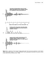
spark gap. Figure 7.37 shows the traces of voltage and current for a spark
of
net electrical
energy 13 mJ, produced by the CMI circuit. The spark discharge was completed after
about 280
ps.
The general apparatus used by CMI was as otherwise shown in Figure 7.34, i.e. similar
to that originally developed by
US
Bureau of Mines.
7.1
0.2.4
A
new international standard method
As
a part of its
efforts
to standardize safe design
of
electrical apparatus in explosible
atmospheres, the International Electrotechnical Commission (1989) is considering a new
test method for the minimum ignition energy
of
dust clouds. The draft is to a large extent
based on work conducted by an international European working group and summarized
by Berthold (1987).
The detailed design of the apparatus to be used in a possible IEC test method, in terms
of explosion vessel, dust dispersion system, synchronization method, etc. was not
specified, but some suitable apparatus were mentioned, including direct high-voltage
discharge circuits as well as the CMI circuit. However, no matter which apparatus is
chosen, the spark generating system must satisfy the following requirements:
Assessment
of
ignitability
52
1
0
Inductance
of
discharge circuit
2
1
mH.
0
Ohmic resistance
of
discharge circuit
<
5
R.
Electrode material: stainless steel, brass, copper
or
tungsten.
0
Electrode diameter: 2.0 mm.
0
Electrode gap:
6
mm.
0
Capacitors: low-inductance type, resistant to surge currents.
0
Capacitance
of
electrode arrangement: as
low
as possible.
0
Insulation resistance between electrodes: sufficiently high to prevent significant leakage
currents.
Figure
7.37
Spark gap voltage and spark current
versus time during discharge of a
13
ml
electric
spark from the
CMI
spark generator. Spark dischar-
ge duration
280
p.
Energy of trigger spark (spike to
the far
left)
is
about
1-2 m/
It will be necessary to take account
of
the possible influences
of
dust concentration, dust
cloud turbulence and degree
of
dust dispersion on the test result. Preliminary tests must be
carried out to adjust the dust dispersion conditions and the ignition delay such that
prescribed minimum ignition energies are actually measured
for
three specified reference
dusts.
522
Dust
Explosions in the Process Industries
Starting with a value
of
spark energy that will reliably cause ignition
of
a given
concentration
of
the dust being tested, the dust concentration being itself a variable, the
test energy is successively halved until no ignition occurs in
10
successive tests. The
minimum ignition energy is defined to lie between the highest energy at which ignition
fails to occur in at least ten successive attempts to ignite the dustlair mixture, and the
lowest energy at which ignition occurs within ten successive attempts.
7.1 1
SENSITIVITY
OF
DUST
LAYERS
TO MECHANICAL IMPACT
AND
FRICTION
7.1
1.1
THE INDUSTRIAL SITUATION
This hazard primarily applies to powders and dusts with explosive properties, Le. which
are able to react
or
decompose exothermally without oxygen supply from the air. Strong
oxothermal reactions may be initiated in layers
of
such materials
if
they are exposed to
high mechanical stresses and fast heating by impact or rubbing, either accidentally
or
as
part
of
an industrial process.
7.1 1.2
LABORATORY TESTS
7.1
1.2.1
Drop
hammer tests
As summarized by Racke (1989), a number of impactlfnction sensitivity test methods have
been developed in several European countries, as well as in USA and Japan. The most
common design concept for the impact test is the drop hammer, as illustrated in Figure
7.38.
Verein deutscher Ingenieure (1988) also mentioned the very similar test by Lutolf
(1978) as a suitable standard method. In the Lutolf test the dust sample size is about 0.10 g
and the theoretical maximum drop hammer impact energy 39
J
(5
kg, 0.8 m). Up to ten
trials are conducted and observations are made with respect
to
occurrence
of
explosion,
flame, smoke
or
sparks. If all ten tests are negative, a new test series is conducted with the
dust samples wrapped in thin aluminium foil (10 pm thickness), in case the aluminium
should have a sensitizing effect on a possible exothermal reaction. If the tests with
aluminium are positive, a new test series without aluminium is conducted.
The American Society for Testing and Materials (1988) adopted the US Bureau of
Mines drop hammer method
as
their standard. Using a fixed drop hammer weight
(2.0
or
3.0 kg), the drop height
H,,
giving
50%
probability
of
a positive reaction, is determined.
The lower
H,,,
the more sensitive the material is to impact ignition. In the test description
Assessment of ignitability
523
Figure
7.38
5
kg
and height of fall
7
m
(From Verein deutscher Ingenieure, 1988)
Drop hammer test for dust layers by Koenen, Ide and Swart
(7
96
I).
Drop hammer mass
it is emphasized that the observation of the reaction
of
the sample is one
of
the difficult
points in impact sensitivity testing.
A
positive test result is defined as an impact that
produces one
or
more
of
the following phenomena: (a) audible reaction, (b) flame or
visible light, (c) definite evidence of smoke (not to be confused with a dust cloud
of
dispersed sample), and (d) definite evidence
of
discolouration
of
the sample due to
decomposition. The problem arises with reactions that yield no distinguishable audible
response, no flame, and little sample consumption. The decision concerning reactiodno
reaction in these cases must be based primarily upon the appearance
of
the sample after
the test. The impact in most cases will compress the sample into a thin disc, portions of
which may adhere to the striking tool surface, the anvil,
or
both. One should then inspect
the tool and anvil surfaces and look for voids in the powder disc and discolouration due to
decomposition in areas where voids occur. If there is discolouration from decomposition,
the test trial is to be considered as positive. If there are small voids but no discolouration,
the trial should be regarded as negative. In the case
of
doubt as to whether
or
not
discolouration
is
present, the trial is to be regarded as negative. If the only evidence is a
slight odour
or
a small amount of smoke, which may be a dust cloud from dispersed
sample, the trial should also be considered negative.
7.1
1.2.2
Friction
tests
As
pointed out by Racke
(1989),
several different friction tests have been devised,
including three described by Gibson and Harper
(1981).
One
of
these is illustrated in
Figure
7.39.
524
Dust Explosions in the Process Industries
Figure
7.39
Example
of
laboratory method for
testing the sensitivity
of
powders to mechanical
rubbing/friction (From Gibson and Harper,
1981)
7.1
2
SENSITIVITY
OF
DUST CLOUDS TO IGNITION
BY
METAL
SPARKS/HOT SPOTS
OR
THERMITE FLASHES
FROM
ACCIDENTAL MECHANICAL IMPACT
7.1
2.1
THE INDUSTRIAL SITUATION
Dense clouds of metal sparks, and also hot surfaces, are easily generated in grinding and
cutting operations. Such operations are therefore generally to be considered as hot work,
which should not be permitted in the presence of ignitable dusts
or
powders.
However, the evaluation of the ignition hazard to be associated with accidental impacts
is less straight-forward. Such impacts can occur due to mis-alignment of moving parts in
powder processing equipment, for example in grinders and bucket elevators. Or foreign
bodies such as stones and tramp metal can get into the process line. Whether
or
not metal
sparks/hot spots
or
thermite flashes from single accidental impacts between solid bodies,
can in fact initiate dust explosions, has remained a controversial issue for a long time. It
now seems that in the past ‘friction sparks’ have been claimed to be the ignition sources of
dust explosions more often than one would consider as reasonable on the basis of more
recent evidence. However, as long as necessary conditions for such impacts to be capable
of initiating dust explosions have been unidentified, one has been forced to maintain the
hypothesis that such sparks may be hazardous in general. This in turn has forced industry
to take precautions that may have been superfluous, and caused fear that may have been
unnecessary.
Generation of metal sparkshot spots by accidental mechanical impacts is a complex
process, involving a number
of
variables such as:
0
Chemistry and structure
of
the material
of
the colliding bodies.
0
Physical and chemical surface properties
of
the colliding bodies.
Shapes of the colliding bodies.
0
Relative velocity of the colliding bodies just before impact.
0
Impact energy (kinetic energy transformed to heat in an impact).
Single or repeated impacts?
Assessment of ignitability
525
Whether a given dust cloud will be ignited by a given impact not only depends on the
specific dust properties, but also on:
0
Dust concentration and dynamic state of the dust cloud.
0
Composition, temperature and pressure
of
the gas phase.
In view
of
the great number of variables and the lack
of
an adequate theory, it is clear
that the ignition experiments on the basis of which the practical hazard is to be assessed,
should resemble the practical impact situation as closely as possible.
7.1
2.2
LABORATORY TESTS
No
standardized test methods have
so
far been traced, but the ability
of
metal sparks/hot
spots from grinding and cutting to ignite dust clouds has been demonstrated in laboratory
tests by several researchers, including Leuschke and Zehr (1962), Zuzuki
et
al.
(1965),
Allen and Calcote (1981) and Ritter (1984). (See Chapter
5.)
Laboratory test methods for the incendivity of single accidental mechanical impacts
seem to be less numerous. A test apparatus developed by Pedersen and Eckhoff (1987), is
illustrated in Figure
7.40.
Figure
7.40
Apparatus for determining the sensitivity of dust clouds
to
ignition by single accidental
mechanical impacts (From Pedersen and Eckhoff,
1987)
526
Dust Explosions in the Process Industries
The basic principle of impact generation is that a spring-loaded rigid arm, which can
swing around a fixed axis, and carries the test object at its tip, is released and hits a test
anvil tangentially at a known velocity. Depending on the normal contact force during
impact, the peripheral velocity
of
the tip
of
the arm will be more or less reduced. By
knowing the mass distribution
of
the arm and the peripheral velocity
of
its tip just before
and just after impact, the impact energy can be estimated in terms of
loss
of kinetic energy
of
the arm. The impact force is varied by varying the excess length
of
the arm compared
with the distance from the arm axis to the anvil.
Figure 7.41 gives an expanded view
of
the test object holder at the arm tip. The dust
cloud was generated by dispersing a given quantity of dust from a dispersion cup by a short
blast
of
air. The dust concentration of the transient cloud near the point
of
impact,
at
the
moment of impact, was measured by a calibrated light attenuation probe. (See Figure 1.76
in Chapter 1.
)
Figure
7.41
Expanded view of test object holder of
apparatus shown in Figure
7.40
(From Pedersen and
Eckhoff,
1987)
Figure 7.42 shows some typical results from experiments with the apparatus shown in
Figure 7.40. Further details
of
this kind
of
experiments are discussed in Chapter
5.
Because of the lack of generally accepted test methods, it has been suggested that the
sensitivity of a dust cloud to ignition by metal sparkshot spots from accidental impacts
may be correlated to the sensitivity
of
ignition by other sources, such as electric sparks.
As
discussed in Chapter
5,
Ritter (1984) found a correlation involving both the minimum
electric spark ignition energy and the minimum ignition temperature as determined by the
BAM
furnace. Table
7.2
indicates a correlation with the minimum electric spark ignition
energy alone.
Assessment of ignitability 527
Figure
7.42
Frequency
of
ignition
of
clouds of
dried maize starch in air as a function of impact
energy at
16
m/s and 24 m/s peripheral velocity
of approach
of
the arm tip. Bars indicate
k
1
standard deviation. Impacts between titanium
and rusty steel (thermite flashes) (From Pedersen
and Eckhoff, 1987)
Table
7.2
Results from single-impact ignition tests
of
dust clouds of different minimum electric spark
ignition energies, using a
20
J
thermite flash impact between titanium and rusty
steel
(From Pedersen
and Eckhoff,
(1987).
7.1
3
MINIMUM EXPLOSIBLE DUST CONCENTRATION
7.1
3.1
THE
INDUSTRIAL SITUATION
For a given type of explosible dust, dispersed as a cloud in air, there is a reasonably well
defined minimum quantity
of
dust per unit volume
of
air below which the dust cloud is not
able to propagate a flame. (See Chapter
4
for full discussion.) In theory, therefore, one
could eliminate the possibility
of
dust explosions by ensuring that the dust concentration
does not exceed this minimum limit. In practice, however, most process equipment in
plants where powders are manufactured and handled will always contain large quantities
of
powder, and hence this principle of preventing dust explosions is not practicable in
general. There are, however, some types
of
process equipment to which the principle may
be adapted in practice (see Section
1.4.3.2).
528
Dust Explosions in the Process Industries
One example is dust extraction systems designed for the purpose
of
extracting a
relatively small quantity
of
fine dust from a coarse main product, as in grain silo plants. In
such cases the concentration
of
dust in the system can often be controlled to some extent
by controlling the flow of air. It is then essential, however, that the air velocity is
maintained sufficiently high to prevent dust from depositing on walls
of
ducting etc.
,
since
such deposits, if redispersed, may form clouds
of
explosible concentration.
Another type
of
equipment that can be protected by keeping the dust concentration
sufficiently low, is systems for electrostatic powder painting. In such systems the
concentration
of
particles in the air is relatively uniform and fairly easy to control. In fact,
several countries have imposed specific maximum permissible average dust concentrations
in the spraying booth, based on estimates
of
the minimum explosible dust concentration.
(See Section
1.5.3.5.)
7.1
3.2
LABORATORY TESTS
Experimental determination
of
the minimum explosible dust concentration is discussed in
detail in Section
4.2.6.2
in Chapter
4.
This also includes comparisons between various test
methods in use.
7.1
3.2.1
Tests developed
in
USA
In the standard test used in USA and
UK
for a number of years and described by Dorsett
et
al.
(1960),
a known quantity of the powder was dispersed as a cloud in a slim, vertical,
cylindrical container of
1.2
litre volume and exposed to a continuous spark ignition source.
Starting with very small powder quantities and repeating the test with steadily increasing
amounts, a critical quantity was reached at which the dust cloud ignited. The critical mass
of
dust, divided by the volume of the test container, was taken as the minimum explosible
dust concentration (MEC).
It was felt that the traditional test method was not fully satisfactory. On the one hand,
the continuous ignition source was located in the lower part of the vertical, elongated
explosion vessel, and this would allow the dust cloud, rising from the dispersion cup
of
the
vessel bottom,
to
become ignited before having been fully dispersed throughout the entire
vessel volume. Hence, the real concentration
of
dust in the cloud at the moment
of
ignition was likely to be higher than the nominal concentration estimated by dividing the
mass
of
dust dispersed by the total vessel volume. This error would generally lead to
underestimation of MEC. On the other hand, the traditional ignition source was a
continuous train
of
relatively weak electric sparks that may not have been sufficiently
energetic for igniting dust clouds of concentrations near the true limit for self-sustained
flame propagation. This would generally yield overestimation
of
MEC. The effects of
these two factors tend
to
cancel each other, and this may be the reason for the surprisingly
good agreement that has in some cases been obtained between MEC values from the
traditional small-scale lab test, and large-scale experiments.
For
example, Jacobson
er
al.
(1961)
found that various grain dusts and starches all gave MEC’s of the order
of
50
s/m3
in the small lab-scale test, which compares favourably with the value
60
g/m3 found for a
Assessment
of
ignitability
529
typical wheat grain dust containing
10%
moisture, in industrial-scale experiments by
Eckhoff and Fuhre
(1975).
However, such good agreement between the small-scale test and large-scale conditions
would not be expected to be the general rule. For this reason, considerable efforts have
been made in several countries during the last decade to develop an improved test for
MEC.
In the
USA,
Hertzberg, Cashdollar and Opferman
(1979)
at the Bureau of Mines first
developed an
8
litre explosion vessel in which transient dust clouds
of
quite homogeneous
concentration distributions could be generated. One important conclusion from these
studies was that determination
of
true MEC-values requires a strong ignition source.
Therefore, Cashdollar and Hertzberg
(1985)
subsequently developed a
20
litre explosion
vessel that would yield meaningful results even with quite strong ignition sources.
A
cross section
of
the
20
litre vessel is shown in Figure
7.43.
A
photograph of the
opened vessel, showing one
of
the light attenuation probes for measuring the dust
concentration development in the transient dust cloud, is given in Figure
7.44.
Figure
7.43
Cross-section
of
US
Bureau
of
Mines’
20
litre explosion vessel for determination
of
the
mifiimum
explosible concentration and other parameters
of
explosible dust clouds (From Cashdollar
and Hertzberg,
1985)
530
Dust Explosions in the Process Industries
Figure
7.44
Photograph of opened
20
litre
US
Bureau of Mines explosion vessel, showing one of the
light attenuation probes for measuring dust concentration (Courtesy of
K.
L.
Cashdollar,
US
Bureau
of
Mines, Pittsburgh,
USA)
Favourable agreement was obtained between minimum explosible concentrations found
for coal dust in large-scale mine experiments and in the
20
litre vessel (Cashdollar
et
al.,
1987).
The ignition source used in the
20
litre sphere was then a strong chemical igniter of
calorific energy about
2500
J.
The criterion of explosion was that the explosion pressure in
the closed vessel should rise to at least twice the absolute initial pressure. For atmospheric
initial pressure this means at least
1
bar(g). In addition the maximum rate
of
pressure
rise
should exceed
5
bark.
7.1
3.2.2
GermadSwiss closed bombs
The
1
m3
IS0
vessel developed by Bartknecht and the
20
litre Siwek vessel are both
discussed in Chapter
4,
and further details are given in Sections 7.16 and 7.17. With the
same ignition source and explosion criterion as used by Cashdollar and Hertzberg, the
Siwek sphere should be able to yield comparable results. If, however, the 10
kJ
igniter
prescribed for the Siwek sphere for determining
P,,
and
Kst
values is used, too low
minimum explosible concentration values would be expected for some dusts.
The
1
m3
IS0
vessel would be expected to yield the most reliable assessment
of
the
minimum explosible concentration. Because
of
the large volume of the dust cloud, even a
very strong ignition source of
10
kJ
would not interfere with the main phase of dust cloud
propagation. However, just because
of
its large size, the
1
m3 test is not very suitable
for
routine testing, and smaller, laboratory-bench-scale methods are needed.
Assessment
of
ignitability
53
1
7.1
3.2.3
Nordtest
Fire
01
1
The Nordtest
(1989)
method was designed specifically to meet the need
of
a reliable
bench-scale test for the minimum explosible concentration
of
dust clouds. The apparatus
consists
of
three main parts:
0
A 15-litre explosion vessel with dust dispersion system.
An ignition system.
0
A dust concentration measurement system.
Figure
7.45
shows a maize starch explosion in the
15
litre Nordtest vessel.
Figure
7.45
Maize starch explosion in
15
litre Nord-
test Fire
0
1 1
vessel. ignition source: Strong electric
arc between two thin metal electrodes
The test procedure consists
of
two consecutive steps. First weighed quantities of the dust
are dispersed into clouds in the 15 litre explosion vessel by means
of
a suitable, defined
blast of air and exposed to
an
effective ignition source. The dispersion mushroom shown in
Figure
7.46
is an essential part
of
the dust dispersion system.
The driving pressure and duration of the air blast are set to yield a reasonably
homogeneous dust cloud in the vessel, as judged visually by the operator. Optimum
dispersion conditions depend on particle size, shape, density and mass
of
dust
to
be
dispersed. Immediately after completion
of
dispersion, the ignition source, positioned
centrally within the cloud, is activated. By varying the dispersed mass
of
dust and
532
Dust Explosions in the Process Industries
Figure
7.46
Dispersion mushroom for Nordtest
Fire
0
1
1
(right) compared with the IEC-version for
the Hartmann bomb (left). Length of match appro-
ximately
50
mm
conducting ten tests at each mass, the mass yielding a probability of explosion
of
50%
is
estimated by interpolation.
The ignition source recommended for the test is a
200
W electric arc
of
0.1
s
duration.
The arc is passed across a
3
mm spark gap between two 1.6 mm
0
metal electrodes. The
arc discharge is initiated by the closing action
of
the solenoid valve of the dust dispersion
system. The ignition source must under no circumstances be less effective than this arc.
However, in exceptional cases, the ignitability
of
the dust to be tested can be
so
low that a
more effective ignition source may be required.
Explosion, i.e. a positive test result, is defined as independent flame propagation
through the experimental dust cloud to the extent that the flame, as observed visually, is
clearly detached from the ignition source.
In the second step
of
the test procedure the actual local dust concentration in the vicinity
of
the ignition source, at the same instant as the ignition source would be activated in the
first step, is determined using the dust mass giving
50%
of ignition, and exactly the same
dust dispersion method as in the ignition tests. The arithmetic mean
of
five consecutive
concentration measurements is taken as the minimum explosible dust concentration.
The version
of
the 15 litre vessel used in the second step is shown in Figure 7.47, and the
basic principle of the traversing dust sampling cylinder is illustrated in Figure 7.48.
7.1
3.2.4
Possible international standard
The International Electrotechnical Commission (1990) is evaluating a test method based
on the
20
litre Siwek (1988) sphere. Nordtest (1989) and the
1
m3 vessel
of
the
International Standardization Organization (1985) are specified as alternative methods.
The explosion criterion is that the maximum explosion pressure should
be
at least 1.5
bar(g). This includes the pressure
of
1.1
f
0.1 bar(g) generated by the powerful chemical
10 kJ igniter only, without dust. Tests are conducted with successively decreasing
dispersed dust masses in steps of
0.2
g until a mass is reached at which the maximum
pressure is lower than 1.5 bar(g) in three consecutive tests with the same dispersed dust
mass. The minimum explosible concentration is then assumed to lie between the highest
nominal concentration (dispersed mass divided by vessel volume) at which the maximum
explosion pressure was less than 1.5 bar(g) in three successive tests, and the lowest
nominal concentration at which the explosion pressure was 1.5 bar(g) or more in one
of
up
to three successive tests.
Assessment of ignitability 533
Figure 7.47
A 15 litre Nordtest Fire
0
1 1
vessel equipped with traversing cylinder for measuring local
dust concentration in the vicinity
of
the ignition source (From Nordtest, 1989).
I
Figure 7.48
Principle
of
Nordtest Fire
0
1
1
dust cloud sampling cylinder (b) compared with that
of
a
simple cylindrical cup
(a)
534
Dust Explosions
in
the Process Industries
As
discussed in Section 4.26.2 in Chapter 4, there are indications of this test method
yielding unexpectedly low minimum explosible dust concentrations for some dusts. This
may be due to the use
of
the very energetic 10 kJ chemical ignition source that may
support propagation
of
flames in dust clouds of lower concentrations than the true
minimum explosible concentration.
This problem is avoided when using the IS0 (1985) method, because the vessel
of
1
m3
volume is sufficiently large for ignition-source-independent flame propagation to be
necessary for generation of significant explosion pressures.
Table 4.9 in Chapter
4
gives comparative data from tests with the three methods, using
the same dusts.
7.1
4
MAXIMUM EXPLOSION PRESSURE
AT
CONSTANT VOLUME
7.1
4.1
THE INDUSTRIAL SITUATION
Most process equipment will not be sufficiently strong to withstand the typical pressures
generated by unvented dust explosions. In principle, strengthening
of
the equipment can
prevent it from bursting, but in general the structures required for achieving the sufficient
strength will have to be
so
heavy that this approach is not generally recommendable,
neither from the point of view of capital cost nor with respect to running and maintaining
the plant. Exceptions are cylindrical dust extraction ducting, which can be made pressure
resistant with reasonable wall thicknesses, and certain types of equipment which is heavy
anyway, such as some mill types.
It nevertheless happens that the concept of fully pressure resistant process plant is
adopted, e.g. when the powders are highly toxic and therefore in no circumstances can be
admitted to outside the equipment. In such cases it is important to know the highest
pressures
to
be expected, should a dust explosion occur within the equipment.
As
discussed in Section
3.3.8,
the maximum explosion pressure (abs.) is generally propor-
tional to the initial pressure (abs.), which must therefore be specified. In the case
of
a dust
explosion in a fully confined, integrated system of various process items connected by
comparatively narrow passages, pressure-piling may easily occur, as discussed in Section
1.4.4.1 in Chapter
1.
This implies that a local explosion in one process unit may raise the
pressure in the unburnt dust clouds elsewhere in the interconnected system. Should the
flame then propagate into this pre-pressurized area, a considerably higher maximum
pressure than if the initial pressure had been atmospheric, can result. Such pressure-piling,
which may escalate in several stages, can give rise
to
local transient explosion pressures
that are substantially higher than the adiabatic maximum explosion pressure at constant
volume generated from normal atmospheric initial pressure. These possibilities must be
considered carefully before adopting laboratory test data for the maximum explosion
pressure, which are normally based on atmospheric initial pressure.
Assessment of ignitability
535
7.1
4.2
LA
BO
RATORY TESTS
7.1
4.2.1
Hartmann bomb
The Hartmann bomb, described by Dorsett
et
ai.
(1960), has been used throughout the
world for assessing the maximum explosion pressure
of
dust clouds for nearly half a
century. This apparatus, which is illustrated in Figures 7.49 and 7.50, basically consists of a
closed vertical
1.2
litre stainless steel cylinder into which a known quantity of dust is
dispersed as a cloud by a blast
of
air and exposed to an ignition source.
Figure
7.49
A
1.2
litre Hartmann bomb for determination ofpressure development in dust explosions
at constant volume. Version developed during multinational cooperation and in all essentials adopted
as
a
standard by the American Society for Testing and Materials
(I
988a)
The dispersion mushroom design adopted in a multinational joint effort through the
International Electrotechnical Commission, and shown in Figure 7.46 differs slightly from
that included in the standard specified by the American Society
of
Testing and Materials
(1988a).
536
Dust Explosions in the Process Industries
Figure
7.50
Photograph of the version
of
the Hart-
rnann bomb shown in Figure
7.49
The ignition sources used include continuous trains
of
electric sparks, single synchro-
nized sparks, synchronized chemical igniters and glowing resistance wire coils. Versions
of
the two latter are shown in Figure
7.51.
For determination
of
maximum pressures the
nature
of
the ignition source is not decisive because the maximum pressure is rather
insensitive to the turbulence
of
the dust cloud at the moment
of
ignition. For the rate
of
pressure rise, however, turbulence is a key parameter and the moment
of
ignition must be
exactly defined. (See Section
7.15.)
Figure
7.51
(instantaneous source) (b) used in Hartmann bomb tests (From Eckhoff, 7976)
Glowing resistance wire coil (continuous ignition source) (a) and chemical match head
Assessment
of
ignirability
537
The development
of
explosion pressure as a function of time is recorded as illustrated in
Figure
7.52
over a range
of
nominal dust concentrations (dispersed dust mass divided by
bomb volume). Due to statistical scatter, several tests have to be determined at each
nominal dust concentration.
A
typical set
of
results is shown in Figure 7.53. This figure
also includes the maximum rate
of
pressure rise, i.e. the maximum value
of
the slope of
the pressure-versus-time curve, which will be discussed separately in Section 7.15.
In
Norway it has been customary to take the highest 95% probability value as the result
of
the test.
For
the example in Figure 7.53 this means a maximum pressure
of
6.8
bar(g).
Figure
7.52
during dust explosion
in
a closed vessel
Typical trace
of
pressure-versus-time
Because of the small volume
of
the Hartmann bomb and its elongated shape, the heat
loss to the vessel wall during the explosion is significant. Therefore the maximum
pressures measured are generally somewhat lower, typically by
25-30%,
than those
generated with the same dusts in larger vessels, such as the
1
m3
IS0
vessel and various
20
litre vessels. This is
so
in spite
of
the fact that the pressures measured in the Hartmann
bomb are not corrected
for
the increased initial pressure due to the dust dispersion air.
The measurement
of
maximum constant-volume pressures generated by dust explosions
in closed bombs is fairly straightforward. Apart from the wall cooling effects in small
bombs, the results do not depend much on the details
of
the experiment as long as the dust
cloud is reasonably well dispersed and the average nominal dust concentration is varied
systematically
to
identify the worst case.
7.14.2.2
The
1
m3
standard
IS0
vessel
Side and top views
of
this apparatus are illustrated schematically in Figure 7.54.
A
container
of
approximately
5
litres capacity and capable
of
being pressurized with air
to
20
bar is attached to the explosion chamber. The container is fitted with a
19
mm
0
opening valve
of
10
ms opening time.
The
container is connected to the explosion
chamber via a 19 mm
0
perforated semicircular spray pipe. The diameter
of
the holes in
the pipe should be in the range
4-6
mm. The number of holes is chosen such that their
total cross-sectional area is approximately
300
mm’.
538
Dust Explosions in the Process industries
Figure
7.53
Typical set of results from Hart-
mann bomb test of
a
given dust.
Bars
represent
k
7
st.
dev. Dotted lines based on Gaussian
distribution (mean
+
1.65
st.
dev.)
The ignition source is a pyrotechnical igniter with a total energy of
10
kJ and arranged
to fire after a fixed delay
of
0.6
s
after onset of dust injection. The mass of the
pyrotechnical ignition source is 2.4 g, and it consists
of
40% zirconium, 30% barium
nitrate, and 30% barium peroxide. It is activated by an electric fuse head. The igniter is
located at the geometric centre
of
the explosion chamber. Two pressure transducers,
linked to a recorder, are fitted to measure the explosion chamber pressure development.
The way
of
determining the maximum explosion pressure is similar to that
of
the
Hartmann bomb test, and Figures 7.52 and 7.53 also applies to the
1
m3 test. However,
due
to
the comparatively large size of the experiment, the amount of dust and the time
required per experiment limit the number
of
tests that are normally performed.
Maximum explosion pressures measured with this apparatus would be expected to be
relatively close to the theoretical maximum adiabatic pressures. Data for a range of dusts
are given in Table
A1
in the Appendix.
Figure 7.55 shows a
1
m3 vessel that would most probably satisfy the ISO-standard
requirement,
if
equipped with appropriate dust dispersion and ignition systems.
Assessment of ignitability
539
Figure
7.54
1
m3 closed vessel specified by the International Standardization Organization
(I
985)
for
determination of maximum explosion pressures and maximum rates ofpressure rise of dust clouds in
air (From Verein deutsche ingenieure,
1988)
Figure
7.55
Fike Corporation,
USA)
1
m3 spherical explosion vessel composed of two detachable hemispheres (Courtesy of
540
Dust Explosions in the Process Industries
7.14.2.3
The
Siwek
20
litre
sphere
This vessel was developed by Siwek (1988) primarily with a view to obtain maximum
explosion pressures and explosion rates in agreement with data from the
1
m3
IS0
vessel.
The Siwek sphere
is
shown in Figure 7.56.
Figure
7.56
A
20
litre Siwek sphere for determina-
tion of pressure development in dust explosions
(Courtesy of
R.
Siwek, Ciba-Ceigy
AG,
Switzerland)
The sphere essentially is a small-scale version of the
1
m3
IS0
vessel. The original dust
dispersion system was of the same type as that
of
the
1
m3
IS0
vessel, consisting
of
a
pressurized dust reservoir, from which the dust was injected into the main vessel through a
perforated tube, as illustrated in Figure 7.54. The experimental conditions required for
obtaining agreement with the
1
m3
IS0
vessel were specified in a standard issued by the
American Society for Testing and Materials (1988b). The ignition source has to be the
same type of 10 kJ chemical igniter as used in the
1
m3 ISO-test. The ignition delay is,
however, shorter
(60
ms) because
of
the smaller vessel size. For the determination
of
the
rate
of
pressure rise (see Section 7.15) it is important to pay attention even
to
the design
of
the capsule containing the pyrotechnical mixture
of
the ignition source. Zhu
et
al.
(1988)
showed that igniters with metal capsules could give significantly different
Kst
values from
those obtained for the same dusts with plastic capsules.
Under these circumstances, and testing dusts
of
small particle size, Siwek obtained quite
good correlations between data from the
1
m3 IS0 vessel and his
20
litre sphere, as shown
in Figure 7.57.
(Ks,
is defined in Section
4.4.3.3
in Chapter
4.)
Experience in several laboratories disclosed, however, that many cohesive dusts, in
particular
of
fibrous particles, can easily get packed and trapped inside the perforated
dispersion tube
of
the original dust dispersion system, which is clearly unsatisfactory. This
led to the development
of
an open nozzle system named a ‘rebound’ nozzle, shown in
Figure 7.58, which has gradually replaced the original perforated ring. According to Siwek
Assessment
of
ignitability
54
1
Fi
ure
7.57
Correlations of maximum explosion pressures and maximum rates ofpressure rise from
1
m
9
IS0
vessel and
20
litre Siwek sphere. Courtesy
of
R.
Siwek, Ciba-Ceigy AC, Switzerland)
Figure
7.58
New rebound nozzle for dispersing the
dust in the
20
litre Siwek sphere (Courtesy
of
R.
Siwek, Ciba-Ceigy AC, Switzerland)
(1988) the new nozzle produces both maximum pressures and
Ksr
values in reasonable
agreement with those generated by the original perforated-ring system.
7.14.2.4
Other
20
litre
vessels
The
US
Bureau
of
Mines vessel described by Cashdollar and Hertzberg (1985) and shown
in Figure 7.59, is a valid alternative to the Siwek vessel.
An
advantage, as demonstrated in
Figure 7.44, is the large opening giving easy access to the inside of the vessel for cleaning,
inspection, etc.
It would be expected that the
US
Bureau of Mines vessel would yield both maximum
explosion pressures and rates
of
pressure rise in agreement with data from the Siwek
sphere provided the dust dispersion and ignition conditions were the same in both vessels.
The
20
litre vessel system described by Burke (1988) was shown to be in accordance with
the standard specified by American Society for Testing and Materials (1988b), for
determination
of
both maximum explosion pressures and maximum rates
of
pressure rise.
Another complete
20
litre vessel test system is illustrated in Figure 7.60.
542
Dust Explosions in the Process industries
Figure
7.59
Photo
of
the
20
litre
US
Bureau
of
Mines vessel with the lid on (Courtesy
of
C.
L.
Cashdollar,
US
Bureau of Mines, Pittsburgh,
USA)
Figure
7.60
(Courtesy
of
Fike Corporation,
USA)
Complete
20
litre sphere system for determining explosibility properties of dusts
Assessment
of
ignitability
543
American Society for Testing and Materials (1988b) also indicate some further
20
litre
test apparatuses and a
26
litre apparatus that are likely to satisfy the requirements
of
the
standard.
7.1
5
MAXIMUM
RATE
OF
RISE
OF
EXPLOSION PRESSURE
AT
CONSTANT VOLUME (EXPLOSION VIOLENCE)
7.1
5.1
THE INDUSTRIAL SITUATION
Industrial enclosures such as conventional process equipment, are normally far too weak
to withstand the pressures exerted even by only partly developed, confined dust
explosions. Consequently a primary objective of fighting an explosion after it has been
initiated, is to prevent the build-up of destructive overpressures.
At least three techniques for preventing destructive overpressures are in current use in
industry. The first and probably most widely used is venting. Another technique is
automatic suppression. In case the explosion starts in an enclosure that is strong enough to
withstand the explosion pressure, such as certain types
of
mills, isolation by high-speed
valves to prevent the explosion from propagating to other, weaker enclosures constitutes a
third means
of
protection.
Regardless
of
which protective technique is adopted, the violence of the dust explosion,
i.e. the rate of heat generation inside the enclosure where the explosion is initiated, is a
deciding factor as to whether a given protective system will perform adequately. In view of
the fact that the combustion rate can vary substantially from dust cloud to dust cloud, it is
important to base the design
of
industrial equipment on appropriate estimates
of
the
explosion violence or combustion rate that will occur in practice.
7.1
5.2
LABORATORY TESTS
Maximum rates of pressure
rise
can be measured in all the closed vessels described in
Section 7.14. Section 4.4.3 in Chapter 4 discusses the basic nature of such experiments,
and it is shown that the maximum rate
of
pressure rise in closed bomb apparatuses
of
the
type discussed in Section 7.14 is bound to be arbitrary. This also applies to
Kst
values
of
dusts (Section 4.4.3.3, equation (4.84)).
The method
for
determining
Ksr
values
of
dusts specified by the International
Standardization Organization (1985) is the same as for measurement
of
maximum
explosion pressure and described in Section 7.14.2.2. Because the standard vessel has a
volume
of
1
m3, the
Kst
values in bar m/s are numerically identical with the maximum rate
of pressure rise in bark.
If smaller vessels, for example of
20
litres, are used for determining
Ksr
values according
to the
IS0
standard, the dust dispersion system, the ignition source strength and the
ignition delay must be tuned in such a way that the products
of
the maximum rates of