Erection Bracing of Low-Rise Structural Steel Buildings phần 1 pdf
Bạn đang xem bản rút gọn của tài liệu. Xem và tải ngay bản đầy đủ của tài liệu tại đây (292.6 KB, 10 trang )
Steel Design Guide Series
Erection Bracing
of Low-Rise Structural Steel Buildings
Steel Design Guide Series
Erection Bracing
of Low-Rise Structured Steel Buildings
James M. Fisher, PhD, P. E.
and Michael A. West, P. E.
Computerized Structural Design
Milwaukee, Wisconsin
AMERICAN INSTITUTE OF STEEL CONSTRUCTION
© 2003 by American Institute of Steel Construction, Inc. All rights reserved.
This publication or any part thereof must not be reproduced in any form without permission of the publisher.
Copyright 1997
by
American Institute of Steel Construction, Inc.
All rights reserved. This book or any part thereof
must not be reproduced in any form without the
written permission of the publisher.
The information presented in this publication has been prepared in accordance with rec-
ognized engineering principles and is for general information only. While it is believed
to be accurate, this information should not be used or relied upon for any specific appli-
cation without competent professional examination and verification of its accuracy,
suitablility, and applicability by a licensed professional engineer, designer, or architect.
The publication of the material contained herein is not intended as a representation
or warranty on the part of the American Institute of Steel Construction or of any other
person named herein, that this information is suitable for any general or particular use
or of freedom from infringement of any patent or patents. Anyone making use of this
information assumes all liability arising from such use.
Caution must be exercised when relying upon other specifications and codes developed
by other bodies and incorporated by reference herein since such material may be mod-
ified or amended from time to time subsequent to the printing of this edition. The
Institute bears no responsibility for such material other than to refer to it and incorporate
it by reference at the time of the initial publication of this edition.
Printed in the United States of America
Second Printing: October 2003
© 2003 by American Institute of Steel Construction, Inc. All rights reserved.
This publication or any part thereof must not be reproduced in any form without permission of the publisher.
TABLE OF CONTENTS
ERECTION BRACING OF
LOW RISE STRUCTURAL
STEEL BUILDINGS
1.
INTRODUCTION
1
1.1 Types of Systems 1
1.2 Current State of the Art 1
1.3 Common Fallacies 2
1.4 Use of This Guide 2
PART 1
DETERMINATION OF BRACING
REQUIREMENTS BY CALCULA-
TION
2.
INTRODUCTION
TO
PART
1
2
3. CONSTRUCTION PHASE LOADS
FOR
TEMPORARY
SUPPORTS
2
3.1 Gravity Loads 3
3.2 Environmental Loads 3
3.2.1 Wind Loads 3
3.2.2 Seismic Loads 4
3.3 Stability Loads 7
3.4 Erection Operation Loads 7
3.5 Load Combinations 7
4. RESISTANCE TO CONSTRUCTION
PHASE LOADS BY THE PERMANENT
STRUCTURE
8
4.1 Columns 10
4.2 Column Bases 11
4.2.1 Fracture of the Fillet Weld Connecting
the Column to the Base Plate 11
4.2.2 Bending Failure of the Base Plate 13
4.2.3 Rupture of Anchor Rods 15
4.2.4 Buckling of the Anchor Rods 15
4.2.5 Anchor Rod Pull or Push Through . 16
4.2.6
Anchor
Rod
Pull
Out
16
4.2.7 Anchor Rod "Push Out" of the
Bottom of the Footing 17
4.2.8
Pier
Bending
Failure
18
4.2.9 Footing Over Turning 18
4.3 Tie
Members
24
4.3.1 Wide Flange Beams 24
4.3.2 Steel Joists 25
4.3.3 Joist Girders 26
4.4 Use of Permanent Bracing 26
4.5 Beam to Column Connections 27
4.6 Diaphragms 27
5. RESISTANCE TO DESIGN LOADS -
TEMPORARY
SUPPORTS
27
5.1 Wire Rope Diagonal Bracing 28
5.2 Wire Rope Connections 34
5.2.1 Projecting Plate 34
5.2.2
Bent
Attachment
Plate
35
5.2.3 Anchor Rods 36
5.3 Design of Deadmen 39
5.3.1 Surface Deadmen 39
5.3.2 Short Deadmen
Near Ground Surface 39
PART 2
DETERMINATION OF BRACING
REQUIREMENTS USING PRE-
SCRIPTIVE REQUIREMENTS
6.
INTRODUCTION
TO
PART
2
41
7. PRESCRIPTIVE REQUIREMENTS
. 41
7.1 Prescriptive Requirements for the Permanent
Construction 41
7.2 Prescriptive Requirements for Erection Sequence
and Diagonal Bracing 42
REFERENCES
59
Acknowledgements
60
APPENDIX
61
© 2003 by American Institute of Steel Construction, Inc. All rights reserved.
This publication or any part thereof must not be reproduced in any form without permission of the publisher.
ERECTION BRACING OF
LOW RISE STRUCTURAL
STEEL BUILDINGS
1. INTRODUCTION
This guide is written to provide useful information
and design examples relative to the design of temporary
lateral support systems and components for low-rise
buildings. For the purpose of this presentation, low-rise
buildings are taken to have the following characteris-
tics:
(1) Function: general purpose structures for such
uses as light manufacturing, crane buildings,
warehousing, offices, and other commercial
and institutional buildings.
(2) Proportions:
(a) height: 60 feet tall or less.
(b) stories: a maximum of two stories.
Temporary support systems are required whenever an
element or assembly is not or has not reached a state of
completion so that it is stable and/or of adequate
strength to support its self-weight and imposed loads.
The need for temporary supports is identified in Para-
graph M4.2 of the AISC Specification for Structural
Steel Buildings and in Section 7 of the AISC Code of
Standard Practice for Steel Buildings and Bridges.
To a great extent the need for this guide on tempo-
rary supports was created by the nature and practice of
design and construction of low-rise buildings. In many
instances, for example, the lateral bracing systems for
low-rise buildings contain elements which are not in the
scope of the steel erector's work. For this reason the
Code of Standard Practice makes a distinction between
Self-Supporting and Non-Self-Supporting framework
as will be discussed later. Other temporary supports
such as shoring and cribbing for vertical loads are not
included in the scope of this guide.
1.1 Types of Systems
Lateral bracing systems for low-rise buildings can
be differentiated as follows:
Braced construction: In this type of system, truss-
like bays are formed in vertical and horizontal
planes by adding diagonals in vertical bays
bounded by columns and struts or in horizontal bays
bounded by beams and girders. In general, braced
construction would be characterized as self-sup-
porting, however, the frames may contain elements
such as a roof deck diaphragm which would change
the frame to a non-self-supporting type.
Rigid Frame Construction: This system uses mo-
ment resisting joints between horizontal and verti-
cal framing members to resist lateral loads by frame
action. In many buildings the rigid frames are dis-
cretely located within the construction to minimize
the number of more costly moment resisting con-
nections. The remainder of the frame would have
simple connections and the frame would be de-
signed to transfer the lateral load to the rigid
frames. Rigid frame construction would also be
characterized as self-supporting, however in the
case of braced construction the framework may
contain non-structural elements in the system
which would make it a non-self-supporting frame.
Diaphragm Construction: This system uses hori-
zontal and/or vertical diaphragms to resist lateral
loads. As stated above horizontal diaphragms may
be used with other bracing systems. Horizontal di-
aphragms are usually fluted steel deck or a concrete
slab cast on steel deck. Vertical diaphragms are
called shear walls and may be constructed of cast-
in-place concrete, tilt-up concrete panels, precast
concrete panels or masonry. Vertical diaphragms
have also been built using steel plate or fluted wall
panel. In most instances, the elements of dia-
phragm construction would be identified as non-
self-supporting frames.
Cantilever Construction: Also called Flag Pole
Construction, this system achieves lateral load re-
sistance by means of moment resisting base con-
nections to the foundations. This system would
likely be characterized as self-supporting unless
the base design required post erection grouting to
achieve its design strength. Since grouting is usual-
ly outside the erector's scope, a design requiring
grout would be non-self-supporting.
Each of the four bracing systems poses different is-
sues for their erection and temporary support, but they
share one thing in common. All as presented in the proj-
ect Construction Documents are designed as complete
systems and thus all, with the possible exception of Can-
tilever Construction, will likely require some sort of
temporary support during erection. Non-self-support-
ing structures will require temporary support of the
erection by definition.
1.2 Current State of the Art
In high-rise construction and bridge construction
the need for predetermined erection procedures and
temporary support systems has long been established in
the industry. Low-rise construction does not command
a comparable respect or attention because of the low
heights and relatively simple framing involved. Also
the structures are relatively lightly loaded and the fram-
1
© 2003 by American Institute of Steel Construction, Inc. All rights reserved.
This publication or any part thereof must not be reproduced in any form without permission of the publisher.
ing members are relatively light. This has lead to a num-
ber of common fallacies which are supported by anec-
dotal evidence.
1.3 Common Fallacies
1. Low-Rise frames do not need bracing. In fact,
steel frames need bracing. This fallacy is probably a
carryover from the era when steel frames were primarily
used in heavy framing which was connected in substan-
tial ways such as riveted connections.
2. Once the deck is in place the structure is stable.
In fact, the steel deck diaphragm is only one component
of a complete system. This fallacy obviously is the re-
sult of a misunderstanding of the function of horizontal
diaphragms versus vertical bracing and may have re-
sulted in the usefulness of diaphragms being oversold.
3. Anchor rods and footings are adequate for erec-
tion loads without evaluation. In fact, there are many
cases in which the loads on anchor rods and footings
may be greater during erection than the loads imposed
by the completed structure.
4. Bracing can be removed at any time. In fact, the
temporary supports are an integral part of the frame-
work until it is completed and self-supporting. This
condition may not even occur until some time after the
erection work is complete as in the case of non-self-
supporting structures.
5. The beams and tie joists are adequate as struts
without evaluation. In fact, during erection strut forces
are applied to many members which are laterally braced
flexural members in the completed construction. Their
axially loaded, unbraced condition must be evaluated
independently.
6. Plumbing up cables are adequate as bracing
cables. In fact, such cables may be used as part of tem-
porary lateral supports. However, as this guide demon-
strates additional temporary support cables will likely
be needed in most situations. Plumbing a structure is as
much an art as a science. It involves continual adjust-
ment commonly done using diagonal cables. The size
and number of cables for each purpose are determined
by different means. For example, the lateral support
cables would likely have a symmetrical pattern whereas
the plumbing up cables may all go in one direction to
draw the frame back to plumb.
7. Welding joist bottom chord extensions produces
full bracing. In fact, the joist bottom chords may be a
component of a bracing system and thus welding them
would be appropriate. However, other components may
be lacking and thus temporary supports would be need-
ed to complete the system. If the joists have not been
designed in anticipation of continuity, then the bottom
chords must not be welded.
8. Column bases may be grouted at any convenient
time in the construction process. In fact, until the col-
umn bases are grouted, the weight of the framework and
any loads upon it must be borne by the anchor rods and
leveling nuts or shims. These elements have a finite
strength. The timing of grouting of bases must be coor-
dinated between the erector and the general contractor.
1.4 Use of This Guide
This guide can be used to determine the require-
ments for temporary supports to resist lateral forces, i.e.
stability, wind and seismic. The guide is divided into
two parts. Part 1 presents a method by which the tempo-
rary supports may be determined by calculation of loads
and calculation of resistance. Part 2 presents a series of
prescriptive requirements for the structure and the tem-
porary supports, which if met, eliminate the need to pre-
pare calculations. The prescriptive requirements of Part
2 are based on calculations prepared using the principles
presented in Part 1.
PART 1
DETERMINATION OF BRACING
REQUIREMENTS BY CALCULA-
TION METHOD
2. INTRODUCTION TO PART 1
Part 1 consists of three sections. The first deals with
design loads which would be applicable to the condi-
tions in which the steel framework exists during the
construction period and specifically during the period
from the initiation of the steel erection to the removal of
the temporary supports. Sections 4 and 5 deal with the
determination of resistances, both of permanent struc-
ture as it is being erected and of any additional tempo-
rary supports which may be needed to complete the tem-
porary support system. An appendix is also presented
which provides tabulated resistances to various compo-
nents of the permanent structure. This appendix follows
the reference section at the end of the guide.
3. CONSTRUCTION PHASE LOADS
FOR TEMPORARY SUPPORTS
The design loads for temporary supports can be
grouped as follows:
Gravity loads
Dead loads on the structure itself
Superimposed dead loads
Live loads and other loads from construction
operations
2
© 2003 by American Institute of Steel Construction, Inc. All rights reserved.
This publication or any part thereof must not be reproduced in any form without permission of the publisher.
Environmental loads
Wind
Seismic
Stability loads
Erection operation
Loads from erection apparatus
Impact loads caused by erection equipment
and pieces being raised within the structure
3.1 Gravity Loads
Gravity loads for the design of temporary supports
consist of the self-weight of the structure itself, the self-
weight of any materials supported by the structure and
the loads from workers and their equipment. Self-
weights of materials are characterized as dead loads.
Superimposed loads from workers and tools would be
characterized as live loads. Gravity loads can be distrib-
uted or concentrated. Distributed loads can be linear,
such as the weight of steel framing members, non-uni-
form such as concrete slabs of varying thicknesses or
uniform such as a concrete slab of constant thickness.
Dead loads can be determined using the unit density
and unit weights provided in the AISC Manual of Steel
Construction, (LRFD Part 7, ASD Part 6) and ASCE
7-93, Tables Cl and C2. Dead loads can also be ob-
tained from manufacturers and suppliers.
Live loads due to workers and their equipment
should be considered in the strength evaluation of par-
tially completed work such as connections or beams
which are unbraced. The live load used should reflect
the actual intensity of activity and weight of equipment.
In general, live loads on the order of 20 psf to 50 psf will
cover most conditions.
3.2 Environmental Loads
The two principal environmental loads affecting
the design of temporary supports are wind and seismic
loads. Other environmental loads such as accumulated
snow or rain water may influence the evaluation of par-
tially completed construction but these considerations
are beyond the scope of this guide.
3.2.1 Wind Loads
Wind loads on a structure are the result of the pas-
sage of air flow around a fixed construction. The load is
treated as a static surface pressure on the projected area
of the structure or structural element under consider-
ation. Wind pressure is a function of wind velocity and
the aerodynamic shape of the structure element. Vari-
ous codes and standards treat the determination of de-
sign and wind pressures slightly differently, however the
basic concept is common to all methods. What follows
is a discussion of the procedure provided in ASCE 7-93
(1) which will illustrate the basic concept.
In ASCE 7-93 the basic design pressure equation
for the main force resisting system for a building is
p = qG
h
C
p
-qh(GC
pi
) Eq.3-1
where
q - 0.00256K(IV)
2
Eq. 3-2
K = velocity pressure coefficient varying with
height and exposure
Exposure classes vary from A (city center) to D
(coastal areas) and account for the terrain
around the proposed structure.
I = an importance factor which varies with the use
of the building, for design of temporary sup-
ports I may be taken as 1.0 without regard to the
end use of the structure
V = the basic wind speed for the area taken from
weather data, usually a 50 year recurrence inter-
val map
G
h
= a factor accounting for gust response varying
with horizontal exposure
C
p
= a factor accounting for the shape of the structure
q
h
= q taken at height, h
GCpi = a factor accounting for internal pressure
This method or one like it would have been used to
determine the wind forces for the design of the lateral
force resisting system for a structure for which tempo-
rary lateral supports are to be designed.
To address the AISC Code of Standard Practice re-
quirement that "comparable" wind load be used, the
same basic wind speed and exposure classification used
in the building design should be used in the design of the
temporary supports.
The design of temporary supports for lateral wind
load must address the fact that the erected structure is an
open framework and as such presents different surfaces
to the wind.
In ASCE 7-93 the appropriate equation for open
structures is:
p = q
z
G
h
C
f
Eq. 3-3
where
q
z
= q evaluated at height z
G
h
= gust response factor G evaluated at height, h,
the height of the structure
3
© 2003 by American Institute of Steel Construction, Inc. All rights reserved.
This publication or any part thereof must not be reproduced in any form without permission of the publisher.
C
f
= a force coefficient accounting for the height and
aerodynamic geometry of the structure or ele-
ment
The current draft of the ASCE Standard "Design
Loads on Structures During Construction" provides a
reduction factor to be applied to the basic wind speed.
This factor varies between 1.0 for an exposure period
more than 25 years and 0.75 for an exposure period of
less than six weeks. The factor for an exposure period
from 6 weeks to one year is 0.8.
To determine a wind design force, the design pres-
sure, p, is multiplied by an appropriate projected area.
In the case of open structures, the projected area is an ac-
cumulated area from multiple parallel elements. The
accumulated area should account for shielding of lee-
ward elements by windward elements. Various stan-
dards have provided methods to simplify what is a rather
complex aerodynamic problem. The elements of the
multiple frame lines can be solid web or open web mem-
bers. Thus, the determination of wind forces requires an
evaluation to determine the correct drag coefficient and
the correct degree of shielding on multiple parallel
members. It also requires the correct evaluation of the
effects of wind on open web members.
This topic has been treated in the following documents:
1. Part A4.3.3 of the "Low Rise Building Systems
Manual" (12) published by the Metal Building
Manufacturers Association.
2. "Wind forces on Structures" (18), Paper No. 3269,
ASCE Transactions, published by the American
Society of Civil Engineers.
3. "Standards for Load Assumptions, Acceptance and
Inspection of Structures" (16), No. 160, published
by the Swiss Association of Engineers and Archi-
tects.
4. "Design Loads for Buildings" (5), German Indus-
trial Standard (DIN) 1055, published by the Ger-
man Institute for Standards.
Perhaps the most direct method is that given in the cur-
rent draft of the ASCE Standard for Design Loads on
Structures During Construction which states:
"6.1.2. Frameworks without Cladding
Structures shall resist the effect of wind acting upon
successive unenclosed components.
Staging, shoring, and falsework with regular rect-
angular plan dimensions may be treated as trussed
towers in accordance with ASCE 7. Unless detailed
analyses are performed to show that lower loads
may be used, no allowance shall be given for shield-
ing of successive rows or towers.
For unenclosed frames and structural elements,
wind loads shall be calculated for each element.
Unless detailed analyses are performed, load reduc-
tions due to shielding of elements in such structures
with repetitive patterns of elements shall be as fol-
lows:
1. The loads on the first three rows of elements
along the direction parallel to the wind shall
not be reduced for shielding.
2. The loads on the fourth and subsequent rows
shall be permitted to be reduced by 15 percent.
Wind load allowances shall be calculated for all ex-
posed interior partitions, walls, temporary enclo-
sures, signs, construction materials, and equipment
on or supported by the structure. These loads shall
be added to the loads on structural elements.
Calculations shall be performed for each primary
axis of the structure. For each calculation, 50% of
the wind load calculated for the perpendicular
direction shall be assumed to act simultaneously."
In this procedure one would use the projected area
of solid web members and an equivalent projected area
for open web members. This effective area is a function
of the drag coefficient for the open web member which
is a function of the solidity ratio. For the types of open
web members used in low-rise construction an effective
area (solidity ratio, (p) equal to 30 percent of the proj-
ected solid area can be used.
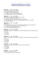
Shielding of multiple parallel elements can be de-
termined using the following equation taken from DIN
1055. See Figures 3.1 and 3.2.
Eq. 3-4
A
where
A = total factored area
= a stacking factor taken from Figure 3.2.
n = the total number of parallel elements
= the projected area of one element
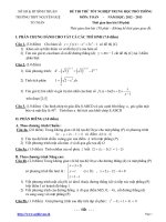
The stacking factor, is a function of the element
spacing to the element depth and a solidity ratio,
3.2.2 Seismic Loads
As indicated in the AISC Code of Standard Prac-
tice, seismic forces are a load consideration in the de-
sign of temporary supports. In general, seismic forces
are addressed in building design by the use of an equiva-
lent pseudo-static design force. This force is a function
of:
1. an assessment of the site specific seismic likelihood
and intensity,
4
© 2003 by American Institute of Steel Construction, Inc. All rights reserved.
This publication or any part thereof must not be reproduced in any form without permission of the publisher.
For the structures within the scope of this guide it is
unlikely that W would include any loads other than dead
load.
The seismic design coefficient, C
s
, is to be deter-
mined using the following equation:
Eq. 3-6
where
A
v
= a coefficient representing the peak velocity re-
lated acceleration taken from a contour map
supplied
S = a coefficient for site soil profile characteristics
ranging from 1.0 to 2.0
R = a response modification factor, ranging from
1.5 to 8.0 depending on the structural system
and the seismic resisting system used
T = the fundamental period of the structure which
can be determined using equations provided
ASCE 7-93 states that the seismic design coeffi-
cient, C
s
, need not exceed the value given by the follow-
ing equation:
where
A
a
= a coefficient representing the effective peak ac-
celeration taken from a contour map supplied
R = the response modification factor described
above
For the structures within the scope of this guide the
response modification factor, R, would be 5.0. This val-
ue for R
w
is taken from ASCE 7, Table 9.3-2 and is the
value given for "Concentrically-braced frames". Like-
wise for the majority of regular structures there is not
significant penalty in using the simpler equation given
above to determine C
s
. The range of values in the con-
tour map provided in ASCE 7-93 are 0.05 through 0.40.
Thus, the range of values for C
s
is 0.025 to 0.20. In gen-
eral wind will govern the design of temporary supports
in areas of low seismic activity such as the mid-west.
Seismic forces will likely govern the design on the west
coast. The value of A
a
would be the same value used in
the design of the completed structure. Although this dis-
cussion of the determination of C
s
would apply to most
structures in the scope of this guide, it is incumbent on
the designer of the temporary support system to be
aware of the requirements for seismic design to confirm
that the general comments of this section apply to the
specific structure at hand.
Fig. 3.1 Parameters for Use
with Fig. 3.2
2. the use of the structure,
3. the geometry and framing system type of the struc-
ture,
4. the geological nature of the building site, and
5. the mass, i.e. self-weight of the structure.
Although codes and standards have differing ap-
proaches to seismic design, they are conceptually simi-
lar. The general approach can be seen in the description
of the approach used in ASCE 7-93 which follows.
The general equation for seismic base shear, V, is:
V = C
S
W Eq.3-5
where
C
s
= the seismic design coefficient
W = the total dead load and applicable portions of
other loads
5
© 2003 by American Institute of Steel Construction, Inc. All rights reserved.
This publication or any part thereof must not be reproduced in any form without permission of the publisher.
Fig. 3.2 Stacking Factor vs. Solidity Ratio
Based on the foregoing in general terms the pseu-
do-static force for seismic design is:
V = 0.05W to 0.40 W
depending on the structure's geographical location. It
should be noted that in this method the seismic base
shear, V, is a strength level value not an allowable stress
value. For single story buildings this force would be ap-
plied at the roof level. For multi-story buildings, a pro-
cedure is given to distribute the force at each story. In
many instances the distribution will be linear, however
in certain conditions of structure location and height the
distribution will be non-linear with the distribution
skewed to the upper stories. Non-linear distribution
will be required when the period of the structure exceeds
5 seconds. The period of the structure can be deter-
mined from equations given in ASCE-7.
For example, a 60-foot-tall structure located where
A
v
equals 0.4 would have a period T of 0.517 seconds.
Whereas a 60-foot-tall structure located where A
v
equals 0.05 would have a period T of 0.733 seconds.
A 40-foot-tall structure in the two locations would
have periods of 0.382 seconds and 0.540 respectively.
The higher periods in the low end of the A
v
range will
likely be of no consequence since the seismic force will
not likely be the governing force. The reader is referred
to ASCE 7-93 for the detailed presentation of vertical
distribution of seismic forces.
The horizontal distribution of seismic force is an
important consideration when seismic force is resisted
by elements in plan connected by longitudinal dia-
phragms or other horizontal systems. In the design of
temporary supports for lateral loads, each frame line
will generally have its own temporary supports so the
6
© 2003 by American Institute of Steel Construction, Inc. All rights reserved.
This publication or any part thereof must not be reproduced in any form without permission of the publisher.