Erection Bracing of Low-Rise Structural Steel Buildings phần 2 pdf
Bạn đang xem bản rút gọn của tài liệu. Xem và tải ngay bản đầy đủ của tài liệu tại đây (150.89 KB, 10 trang )
the exact effect of the seismic force due to the seismic
base shear but must be modified by the following equa-
tions taken from ASCE 7, paragraph 9.3.7:
in Equation A4-5: E and
in Equation A4-6:
E
where
E = the effect of horizontal and vertical earthquake-
induced forces
A
v
= the coefficient representing effective peak ve-
locity-related acceleration from ASCE 7
D = the effect of dead load, D
Q
E
= the effect of horizontal seismic (earthquake-in-
duced) forces
The term 0.5 A
V
D is a corrective term to reconcile
the load factors used in the NEHRP requirements and
the load factors used in the ASCE 7/LRFD require-
ments. This correction is described in detail in the Com-
mentary to ASCE 7, which concludes that the correction
is made separately " so that the original simplicity of
the load combination equations in Sec. 2 is maintained."
It is also explained in this paragraph taken from the
Commentary to the AISC Seismic Provisions:
"The earthquake load and load effects E in ASCE
7-93 are composed of two parts. E is the sum of the
seismic horizontal load effects and one half of A
v
times the dead load effects. The second part adds an
effect simulating vertical accelerations concurrent
to the usual horizontal earthquake effects."
In forming combinations containing the effects of
stability, the load factors for the load source (D or L)
which induces the PA effect would be used for the load
factor(s) on the effect of stability.
In the authors' earlier paper (11) on this topic the
following ASD combinations were recommended:
a. Stability loading
b. 0.75 (stability loading plus wind loading)
These combinations reflected the current ASD Specifi-
cation provision for one-third increases for stresses
computed for combinations including wind loading,
acting alone or in combination with dead and live load.
In this Guide the determination of load and resis-
tance is based on the LRFD Specification. Allowable
stress design is used only when LRFD procedures are
not available or would be inappropriate.
4. RESISTANCE TO CONSTRUCTION
PHASE LOADS BY THE PERMANENT
STRUCTURE
The resistance to loads during construction on the
steel framework is provided by a combination of the per-
manent work supplemented by temporary supports as
needed. The resistance of the permanent structure de-
velops as the work progresses. In a self-supporting
structure the resistance is complete when the erector's
work is complete. In a non-self-supporting structure
resistance will be required after the completion of the
erectors work and will be needed until the other non-
structural-steel elements are in place. During the erec-
tion of both self-supporting and non-self-supporting
frames, conditions will arise which require resistance to
be supplied by the partially completed work. If the re-
sistance of the partially completed work is not adequate,
it must be supplemented by temporary supports.
Elements of the permanent structure which may be
used to resist loads during construction are:
1. Columns
2. Column Bases
3. Beams and Joists
4. Diagonal Bracing
5. Connections
6. Diaphragms
Columns
In general columns will have the same unbraced
length in the partially completed work as in the com-
pleted work so their axial design strength would be the
same during erection as the completed work. The ex-
ceptions would be:
Columns which are free standing on their bases be-
fore other framing and bracing is installed.
Columns supported on leveling nuts or shims prior
to grouting.
Columns which are to be laterally braced by girts or
struts.
Columns which have additional axial load due to
the temporary support system.
Column Bases
The column bases of the permanent structure are an
essential element of both the permanent structure and
the temporary support system. The column bases trans-
fer vertical and lateral loads from the structural steel
framework to the foundation and thence to the ground.
The components of a column base are:
8
© 2003 by American Institute of Steel Construction, Inc. All rights reserved.
This publication or any part thereof must not be reproduced in any form without permission of the publisher.
the base plate and its attachment to the column shaft
the anchor rods
the base plate grout
the supporting foundation.
Base Plate: Column base plates are square or rectangu-
lar plates which transfer loads from the column shaft to
the foundation. In high-rise construction and in other
cases of very high loading, large column bases are some-
times shipped and set separately from the column shafts.
In the case of low-rise and one story buildings, the base
plates are usually shipped attached the column shafts.
The column base reaction is transferred to the column
by bearing for compression forces and by the column to
base plate weld for tension and shear.
Anchor Rods: Anchor rods have in the past been called
anchor bolts. This Design Guide uses the term anchor
rod which has been adopted by AISC in the 2nd edition
of the LRFD Manual of Steel Construction to distin-
guish between bolts, which are generally available in
lengths up to eight inches, and longer headed rods, such
as threaded rods with a nut on the end, and hooked rods.
In the completed construction (with the base plates
grouted) anchor rods are designed to carry tension
forces induced by net tension in the column, base bend-
ing moments and tension induced by shear friction re-
sisting column base shears. During erection operations
and prior to base plate grouting, anchor rods may also
resist compression loads and shears depending on the
condition of temporary support for the column and the
temporary lateral support system. Anchor rods are em-
bedded in the cast-in-place foundation and are termi-
nated with either a hook or a headed end, such as a heavy
hex nut with a tack weld to prevent turning.
Base Plate Grout: High strength, non-shrink grout is
placed between the column base plate and the support-
ing foundation. Where base plates are shipped loose,
the base plates are usually grouted after the plate has
been aligned and leveled. When plates are shipped at-
tached to the column, three methods of column support
are:
1. The use of leveling nuts and, in some cases,
washers on the anchor rods beneath the base
plates.
2. The use of shim stacks between the base plate
bottoms and top of concrete supports.
3. The use of 1/4" steel leveling plates which are
set to elevation and grouted prior to the setting
of columns.
Leveling nuts and shim stacks are used to transfer
the column base reactions to the foundation prior to the
installation of grout. When leveling nuts are used all
components of the column base reaction are transferred
to the foundation by the anchor rods. When shims are
used the compressive components of the column base
reaction are carried by the shims and the tension and
shear components are carried by the anchor rods.
Leveling nuts bear the weight of the frame until
grouting of the bases. Because the anchor rod, nut and
washers have a finite design strength, grouting must be
completed before this design strength would be exceed-
ed by the accumulated weight of the frame. For exam-
ple, the design strength of the leveling nuts may limit the
height of frame to the first tier of framing prior to grout-
ing. Also, it is likely that the column bases would have
to be grouted prior to placing concrete on metal floor
deck.
Properly installed shim stacks can support signifi-
cant vertical load. There are two types of shims. Those
which are placed on (washer) or around (horseshoe) the
anchor rods and shim stacks which are independent of
the anchor rods. Shims placed on or around the anchor
rods will have a lesser tendency to become dislodged.
Independent shims must have a reasonable aspect ratio
to prevent instability of the stack. In some instances
shim stacks are tack welded to maintain the integrity of
the stacks. When shim stacks are used, care must be tak-
en to insure that the stacks cannot topple, shift or be-
come dislodged until grouting. Shims are sometimes
supplemented with wedges along the base plate edges to
provide additional support of the base plate.
Pregrouted leveling plates eliminate the need to
provide temporary means for the vertical support for the
column. The functional mechanisms of the base are the
same in the temporary and permanent condition once
the anchor rod nuts are installed.
The design of base plates and anchor rods is treated
extensively in texts and AISC publications such as the
Manual of Steel Construction and AISC Design Guides
1(7) and 7(10).
Foundations: Building foundations are cast-in-place
concrete structures. The element which usually re-
ceives the anchor rods may be a footing, pile cap, grade
beam, pier or wall. The design requirements for cast-
in-place concrete are given in building codes which
generally adopt the provisions of the American Con-
crete Institute standards such as ACI 318 "Building
Code Requirements for Reinforced Concrete and Com-
mentary"(3). The principal parameter in the design and
evaluation of cast-in-place concrete is the 28-day cyl-
inder compression stress, f'
c
. Axial compressive
strength, flexural strength, shear strength, reinforcing
bar development and the development of anchor rods
are a function of the concrete compressive strength, f'
c
.
Axial tension and flexural tension in concrete elements
is carried by deformed reinforcing bars to which force is
transferred by development of the bar which is a func-
tion of an average bond stress. Bar development is a
function of concrete strength, reinforcement strength,
bar size, bar spacing, bar cover and bar orientation.
9
© 2003 by American Institute of Steel Construction, Inc. All rights reserved.
This publication or any part thereof must not be reproduced in any form without permission of the publisher.
Columns are sometimes supported on masonry pi-
ers rather than concrete piers. In this case the strength of
the piers would be evaluated using ACI 530 "Building
Code Requirements for Masonry Structures" (2) or
another comparable code. Masonry is constructed as
plain (unreinforced) or reinforced. Unreinforced ma-
sonry construction has very low tensile strength and thus
unguyed cantilevered columns would be limited to
conditions where relatively little base moment resis-
tance is required. Reinforced masonry can develop
strengths comparable to reinforced concrete. The ma-
sonry enclosing the grout and reinforcement must be
made large enough to also accommodate and develop
the anchor rods.
In some instances steel columns are erected on
bases atop concrete or masonry walls. In these condi-
tions the side cover on the anchor rods is often less than
it would be in a pier and significantly less than it would
be in the case of a footing. Although not specifically ad-
dressed in this guide, the design strength of the anchor
rod can be determined based on the procedures provided
in this Guide in conjunction with the requirements of
ACI 318 or ACI 530 as appropriate. The wall itself
should be properly braced to secure it against loads im-
posed during the erection of the steel framing.
The erection operation, sequence of the work, reac-
tions from temporary supports and the timing of grout-
ing may cause forces in the anchor rods and foundation
which exceed those for which the structure in its com-
pleted state has been designed. This Guide provides
procedures to evaluate the anchor rods and foundation
for such forces.
One condition of loading of the column base and
foundation occurs when a column shaft is set on the an-
chor rods and the nuts are installed and tightened. Un-
less there is guying provided, the column is a cantilever
from the base and stability is provided by the develop-
ment of a base moment in the column base. This condi-
tion is addressed in detail subsequently in this Guide.
Diagonal cables for temporary lateral support also
induce tensions and shears in the column base which
must be transferred from the column base, through the
anchor rods to the foundation.
Lastly, the structural frame when decked may be
subject to wind uplift which is not counterbalanced by
the final dead load. A net uplift in the column base may
induce forces in the base plates and welds, anchor rods,
and foundation which exceed those for which the struc-
ture in its completed state was designed.
Beams and Joists
Framing members on the column center lines act as
tie members and struts during erection. As such they are
subject to axial forces as well as gravity load bending. In
most cases the axial compression strength of tie mem-
bers and struts will be limited by their unbraced length in
the absence of the flange bracing. The resistance of strut
and tie members must be evaluated with the lateral brac-
ing in place at the time of load application.
Diagonal Bracing
Permanent horizontal and vertical bracing systems
can function as temporary bracing when they are initial-
ly installed. When a bracing member is raised, each end
may only be connected with the minimum one bolt, al-
though the design strength may be limited by the hole
type and tightening achieved. The bracing design
strength may also be limited by other related conditions
such as the strength of the strut elements or the base con-
nection condition. For example, the strut element may
have a minimum of two bolts in each end connection,
but it may be unbraced, limiting its strength.
Connections
Structural steel frames are held together by a multi-
tude of connections which transfer axial force, shear and
moment from component to component. During erec-
tion connections may likely be subjected to forces of a
different type or magnitude than that for which they
were intended in the completed structure. Also, connec-
tions may have only some of the connectors installed
initially with the remainder to be installed later. Using
procedures presented in texts and the AISC Manual of
Steel Construction the partially complete connections
can be evaluated for adequacy during erection.
Diaphragms
Roof deck and floor deck (slab) diaphragms are fre-
quently used to transfer lateral loads to rigid/braced
framing and shear walls. Diaphragm strength is a func-
tion of the deck profile and gage, attachments to sup-
ports, side lap fastening and the diaphragm's anchorage
to supporting elements, i.e., frames and shear walls.
Partially completed diaphragms may be partially effec-
tive depending on the diaphragm geometry, extent of at-
tachment and the relation of the partially completed sec-
tion to the supporting frames or walls. Partially
completed diaphragms may be useful in resisting erec-
tion forces and stabilizing strut members, but the degree
of effectiveness must be verified in the design of the
temporary support system analysis and design.
4.1 Columns
Exceptions were listed earlier wherein the columns
may not have the same length as they would in the com-
pleted structure. Before using the permanent columns
in the temporary support system the erector must evalu-
ate whether the columns have the required strength in
the partially completed structure.
Specific guidelines for this evaluation are not pres-
ented here, because of the many variables that can oc-
10
© 2003 by American Institute of Steel Construction, Inc. All rights reserved.
This publication or any part thereof must not be reproduced in any form without permission of the publisher.
cur. Basic structural engineering principles must be ap-
plied to each situation.
4.2 Column Bases
Probably the most vulnerable time for collapse in
the life of a steel frame occurs during the erection se-
quence when the first series of columns is erected. After
the crane hook is released from a column and before it is
otherwise braced, its resistance to overturning is depen-
dent on the strength (moment resistance) of the column
base and the overturning resistance of the foundation
system. Once the column is braced by tie members and
bracing cables it is considerably more stable.
It is essential to evaluate the overturning resistance
of the cantilevered columns. Cantilevered columns
should never be left in the free standing position unless it
has been determined that they have the required stability
to resist imposed erection and wind loads.
In order to evaluate the overturning resistance one
must be familiar with the modes of failure which could
occur. The most likely modes of failure are listed below.
It is not the intent of this design guide to develop struc-
tural engineering equations and theories for each of
these failure theories, but rather to provide a general
overview of each failure mode and to apply existing
equations and theories. Equations are provided to obtain
the design strength for each mode based on structural
engineering principles and the AISC LRFD Specifica-
tion.
Modes of Failure:
1. Fracture of the fillet weld that connects the column
to the base plate.
2. Bending failure of the base plate.
3. Tension rupture of the anchor rods.
4. Buckling of the anchor rods.
5. Anchor rod nut pulling or pushing through the base
plate hole.
6. Anchor rod "pull out" from the concrete pier or
footing.
7. Anchor rod straightening.
8. Anchor rod "push out" of the bottom of the footing.
9. Pier spalling.
10. Pier bending failure.
11. Footing overturning.
For a quick determination of the resistance for each
of the failure modes, tables are presented in the Appen-
dix.
11
4.2.1 Fracture of the Fillet Weld Connecting the
Column to the Base Plate.
Cantilevered columns are subjected to lateral erec-
tion and wind forces acting about the strong and/or the
weak axis of the column. Weld fractures between the
column base and the base plate are often found after an
erection collapse. In the majority of cases the fractures
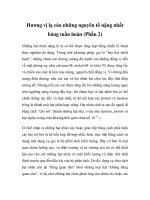
Fig. 4.3 Rupture of Anchor Rods
Fig. 4.2 Bending Failure of Base Plate
Figures 4.1 through 4.11 shown below represent each of
the failure modes.
Fig. 4.1 Fracture of Weld
© 2003 by American Institute of Steel Construction, Inc. All rights reserved.
This publication or any part thereof must not be reproduced in any form without permission of the publisher.
Fig. 4.4 Anchor Rod Buckling
Fig. 4.7 Anchor Rod Straightening
Fig. 4.5 Anchor Rod Pull Through
Fig. 4.6 Anchor Rod Pull Out
Fig. 4.8 Anchor Rod Push Out
are secondary, i.e. some other mode of failure initiated
the collapse, and weld failure occurred after the initial
failure. Fracture occurs when the weld design strength is
exceeded. This normally occurs for forces acting about
the weak axis of the column, because the strength of the
12
weld group is weaker about the weak axis, and because
the wind forces are greater when acting against the weak
axis, as explained earlier.
The design strength of the weld between the col-
umn and the base plate can be determined by calculating
the bending design strength of the weld group. Applied
© 2003 by American Institute of Steel Construction, Inc. All rights reserved.
This publication or any part thereof must not be reproduced in any form without permission of the publisher.
Fig. 4.9 Pier Spalling
Fig. 4.10 Pier Bending Failure
shear forces on the weld are small and can be neglected
in these calculations.
For bending about the column strong axis the de-
sign strength of the weld group is:
Eq. 4-1
For bending about the column weak axis the design
strength of the weld group is:
Eq. 4-2
F
w
= the nominal weld stress, ksi
13
Fig. 4.11 Footing Overturning
=
1.5(0.60)
F
EXX
,
ksi
(for
90°
loading)
F
EXX
=
electrode
classification
number,
i.e.
minimum
specified strength, ksi
S
x
= the section modulus of the weld group about its
strong axis, in.
3
S
y
= the section modulus of the weld group about its
weak axis, in.
3
4.2.2 Bending Failure of the Base Plate.
Ordinarily a bending failure is unlikely to occur.
Experience has shown that one of the other modes of
failure is more likely to govern. A bending failure re-
sults in permanent bending distortion (yielding) of the
base plate around one or more of the anchor rods. The
distortion allows the column to displace laterally, result-
ing in an increased moment at the column base, and
eventual collapse. The design strength of the base plate
is dependent on several variables, but it primarily de-
pends on the base plate thickness, the support points for
the base plate, and the location of the anchor rods.
The design strength of the base plate can be conser-
vatively determined using basic principles of strength of
materials.
Case A: Inset Anchor Rods - Wide Flange Columns.
Yield line theories can be used to calculate the
bending design strength of the base plate for moments
about the x and y axes. The lowest bound for all possible
yield lines must be determined. The approach used here
is a simplification of yield line theory and is conserva-
tive.
The design strength of the base plate is determined
using two yield lines. Shown in Figure 4.12 are the two
yield line lengths used, b
1
and b
2
- The length b
1
is taken
as two times d
1
, the distance of the anchor rod to the cen-
© 2003 by American Institute of Steel Construction, Inc. All rights reserved.
This publication or any part thereof must not be reproduced in any form without permission of the publisher.
Fig. 4.13 Base Plate with Leveling Nuts
ter of the column web. The length b
2
is taken as the
flange width divided by two. The yield line b
2
occurs as
a horizontal line through the bolt Centerline.
Using the dimensions shown in Figure 4.12, the de-
sign strength for a single anchor rod is:
Eq. 4-3
where
the anchor rod force which causes the base plate
to reach its design strength, kips
the plastic moment resistance based on b
1
in
kips
the plastic moment resistance based on b
2
, in
kips
Fig. 4.15 Effective Width
Currently the AISC standard detail illustrates weld
only along the flanges, unless shown otherwise on the
contract drawings. The addition of a fillet weld along
one side of the web adds considerable strength to the
14
Fig. 4.14 Base Plate with Shim Stacks
Fig. 4.12 Base Plate Dimensions
=
0.90
Eq. 4-3 is based on d
1
and d
2
being approximately
equal.
After determining the design strength of the
base plate is determined by multiplying by the ap-
propriate lever arm, d or g is multiplied by two if the
base condition consists of two anchor rods in tension).
Eq.4-4
If leveling nuts are used under the base plate the le-
ver arm (d) is the distance between the anchor rods. See
Figure 4.13. If shim stacks are used then the lever arm
(d) is the distance from the anchor rods to the center of
the shim stack. See Figure 4.14. See discussion of the
use of shims at the beginning of this section.
© 2003 by American Institute of Steel Construction, Inc. All rights reserved.
This publication or any part thereof must not be reproduced in any form without permission of the publisher.
connection. Without the web weld only the length b
2
would be used in the strength calculations.
Case B: Outset Rods - Wide Flange Columns
The authors are unaware of any published solutions
to determine base plate thickness or weld design
strength for the base plate - anchor rod condition shown
in Figure 4.15. By examining Figure 4.15 it is obvious
that the weld at the flange tip is subjected to a concentra-
tion of load because of the location of the anchor rod.
The authors have conducted elastic finite element anal-
ysis in order to establish a conservative design proce-
dure to determine the required base plate thickness and
weld design strength for this condition. The following
conclusions are based on the finite element studies:
1. The effective width of the base plate, b
e
, should
be taken as 2L.
2. The maximum effective width to be used is
five inches.
3. A maximum weld length of two inches can be
used to transmit load between the base plate
and the column section. If weld is placed on
both sides of the flange then four inches of
weld can be used.
4. The base plate thickness is a function of the
flange thickness so as not to over strain the
welds.
In equation format the design strength for a single
anchor rod can be expressed as follows:
Eq. 4-5
Eq. 4-6
Eq. 4-7
Based on the plate effective width:
Based on weld strength:
Based on weld strain:
where
=
0.90
= 0.75
b
e
= the effective plate width, in.
L = the distance of the anchor rod to the flange tip,
in.
t = the throat width of the weld, in.
t
p
= the base plate thickness, in.
F
y
= the specified yield strength for the base plate,
ksi
F
w
= the nominal weld stress, ksi
= 0.9 FEXX, ksi (90° loading)
FEXX
=
electrode
classification
number,
ksi
Using the controlling value for and d:
Eq. 4-8
Case C Outset Rods with hollow structural section
(HSS) columns.
When hollow structural section (HSS) columns are
used, Eq. 4-5 and Eq. 4-7 can be used to calculate
however, if fillet welds exist on all four sides of the col-
umn, then four inches of weld length at the corner of the
HSS can be used for the calculation of in Eq. 4-6.
Thus:
Eq.4-9
4.2.3 Rupture of Anchor Rods
A tension rupture of the anchor rods is often ob-
served after an erection collapse. This failure occurs
when the overturning forces exceed the design strength
of the anchor rods. Fracture usually occurs in the root of
the anchor rod threads, at or flush with, the face of the
lower or upper nut. Anchor rod rupture may be precipi-
tated by one of the other failure modes. It is generally
observed along with anchor rods pulling out of the con-
crete pier, or footing. Shown in Figure 4.3 is an anchor
rod tension failure. The tension rupture strength for rods
is easily determined in accordance with the AISC speci-
fication.
Eq. 4-10
where
= 0.75 (Table J3.2)
= the tension rod design strength, kips
F
n
= nominal tensile strength of the rod F
t
, ksi
F
t
= 0.75F
U
(Table J3.2)
F
u
= specified minimum tensile strength, ksi
A
b
= nominal unthreaded body area of the anchor
rod, in.
2
For two anchor rods in tension the bending design
strength can again be determined as:
Eq.
4-11
4.2.4 Buckling of the Anchor Rods
The buckling strength of the anchor rods can be cal-
culated using the AISC LRFD Specification (Chapter
15
© 2003 by American Institute of Steel Construction, Inc. All rights reserved.
This publication or any part thereof must not be reproduced in any form without permission of the publisher.
E). For base plates set using leveling nuts a reasonable
value for the unbraced length of the anchor rods is the
distance from the bottom of the leveling nut to the top of
the concrete pier or footing. When shim stacks are used
the anchor rods will not buckle and this failure mode
does not apply. It is suggested that the effective length
factor, K, be taken as 1.0, and that the nominal area (A
b
)
be used for the cross sectional area.
For anchor rod diameters greater than 3/4 inches
used in conjunction with grout thickness not exceeding
8 inches, the authors have determined that buckling
strength of the anchor rods will always exceed the de-
sign tensile strength of the rods. Thus this failure mode
need not be checked for most situations.
4.2.5 Anchor Rod Pull or Push Through
The nuts on the anchor rods can pull through the
base plate holes, or when leveling nuts are used and the
column is not grouted, the base plate can be pushed
through the leveling nuts. Both failures occur when a
washer of insufficient size (diameter, thickness) is used
to cover the base plate holes. No formal treatise is pres-
ented herein regarding the proper sizing of the washers;
however, as a rule of thumb, it is suggested that the
thickness of the washers be a minimum of one third the
diameter of the anchor rod, and that the length and width
of the washers equal the base plate hole diameter plus
one inch.
Special consideration must be given to base plate
holes which have been enlarged to accommodate mis-
placed anchor rods.
4.2.6 Anchor Rod Pull Out
Shown in Figure 4.6 is a representation of anchor rod
pull out.
This failure mode occurs when an anchor rod (a
hooked rod or a nutted rod) is not embedded sufficiently
in the concrete to develop the tension strength of the rod.
The failure occurs in the concrete when the tensile
stresses along the surface of a stress cone surrounding
the anchor rod exceed the tensile strength of the con-
crete. The extent of the stress cone is a function of the
embedment depth, the thickness of the concrete, the
spacing between the adjacent anchors, and the location
of free edges of in the concrete. This failure mode is
presented in detail in Appendix B of ACI 349-90(4).
The tensile strength of the concrete, in ultimate strength
terms, is represented as a uniform tensile stress of
over the surface area of these cones. By examin-
ing the geometry, it is evident that the pull out strength
of a cone is equal to times the projected area, A
e
,
of the cone at the surface of the concrete, excluding the
area of the anchor head, or for the case of hooked rods
the projected area of the hook.
The dotted lines in Figure 4.16 represent the failure
cone profile. Note that for the rods in tension the cones
will be pulled out of the footing or pier top, whereas the
cones beneath the rods in compression will be pushed
out the footing bottom. This latter failure mode will be
discussed in the next section.
Depending on the spacing of the anchor rods and
the depth of embedment of the rods in the concrete, the
failure cones may overlap. The overlapping of the fail-
ure cones makes the calculation of A
e
more complex.
Based on AISC's Design Guide 7 the following
equation is provided for the calculation of A
e
which
covers the case of the two cones overlapping.
where
L
d
= the embedment depth, in.
c = the rod diameter for hooked rods, in., and 1.7
times the rod diameter for nutted rods (the 1.7
factor accounts for the diameter of the nut)
s = the rod spacing, in.
Thus, the design strength of two anchor rods in tension
is:
Eq. 4-13
where
-
0.85
f'
c
= the specified concrete strength, psi
When the anchor rods are set in a concrete pier, the
cross sectional area of the pier must also be checked.
Conservatively, if the pier area is less than A
e
then the
pier area must be used for A
e
in the calculation of
(Eq.4-13).
Also when anchor rods are placed in a pier the proj-
ected area of the cone may extend beyond the face of the
pier. When this occurs A
e
must be reduced. The pullout
strength can also be reduced by lateral bursting forces.
The failure mode shown in Figure 4.9 is representative
of these failure modes. These failure modes are also dis-
cussed in AISC's Design Guide 7. Conservatively A
e
can be multiplied by 0.5 if the edge distance is 2 to 3 in-
ches.
It is recommended that plate washers not be used
above the anchor rod nuts. Only heavy hex nuts should
be used. Plate washers can cause cracks to form in the
concrete at the plate edges, thus reducing the pull out re-
sistance of the anchor rods. The heavy hex nuts should
16
© 2003 by American Institute of Steel Construction, Inc. All rights reserved.
This publication or any part thereof must not be reproduced in any form without permission of the publisher.