Erection Bracing of Low-Rise Structural Steel Buildings phần 3 ppsx
Bạn đang xem bản rút gọn của tài liệu. Xem và tải ngay bản đầy đủ của tài liệu tại đây (154.76 KB, 10 trang )
Per ACI 318, (0.70) is the factor for bearing on con-
crete, and the value (2) represents the strength increase
due to confinement.
The design strength obtained from Eq. 4-14 must
be compared to the strength obtained from the failure
cones, Eq. 4-13. The lower value provides the ultimate
strength of the hooked rod to be used in the calculation
for the bending moment design strength associated with
rod pull out.
Eq. 4-15
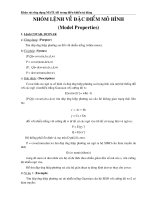
4.2.7 Anchor Rod "Push Out" of the Bottom of the
Footing
Anchor rod push out can occur when the rod is
loaded to the point where a cone of concrete below the
anchor rod is broken away from the footing. This failure
mode is identical to anchor rod pull out but is due to a
compressive force in the rod rather than a tension force.
This failure mode does not occur when shim stacks are
used, when piers are present or when an additional nut is
placed on the anchor rods just below the top of the foot-
ing as shown in Figure 4.17.
Fig. 4.17 Prevention of Push Out
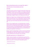
Shown in Figure 4.18 is the individual failure cone
for a nutted anchor rod, and the equation for A
e
. The de-
sign strength for this mode of failure is:
Fig. 4.18 Push Out Cones
Eq. 4-16
where
.75
f'
c
= the concrete compressive strength, psi
17
SECTION A
Fig. 4.16 Failure Cones
be tack welded to the anchor rods to prevent the rod from
turning during tightening operations.
For hooked anchor rods an additional check must be
made, because hooked rods can fail by straightening and
pulling out of the concrete. When this occurs, the rods
appear almost perfectly straight after failure. To prevent
this failure mode from occurring the hook must be of
sufficient length. The hook pullout resistance can be de-
termined from the following equation:
Eq.4-14
where
Hook Bearing Design Strength, kips
f'
c
= the concrete compressive strength, psi
the diameter of the anchor rod, in.
the length of the hook, in.
© 2003 by American Institute of Steel Construction, Inc. All rights reserved.
This publication or any part thereof must not be reproduced in any form without permission of the publisher.
The push out design strength for hooked anchor rods is
assumed to equal that of the nutted rod.
4.2.8 Pier Bending Failure
The design strength of a reinforced concrete pier in
bending is calculated using reinforced concrete prin-
ciples. The required procedure is as follows:
Determine the depth of the compression area.
C = T
0.85f'
c
ba = F
y
A
s
a
C - 0.85f'
c
ab
d = the effective depth of the tension reinforcing
= pier depth - cover - 1/2 of the bar diameter
C(d-a/2) Eq. 4-17
In addition, to insure that the reinforcing steel can
develop the moment, the vertical reinforcement must be
fully developed. Based on ACI 318-95 (12.2.2.), the re-
quired development length can be determined from the
equations below. These equations presume that ACI col-
umn ties, concrete cover, and minimum spacing criteri-
on are satisfied.
For the hooked bar in the footing:
Eq. 4-18
For straight bars (#6 bars and smaller) in the pier:
Eq. 4-19
For straight bars (#7 bars and greater) in the pier:
Eq. 4-20
where
1
dh
= the development length of standard hook in ten-
sion, measured from critical section to out-side
end of hook, in. (See Figure 4.19)
1
d
= development length, in.
f'
c
= specified concrete strength, psi
d
b
= the bar diameter, in.
If the actual bar embedment length is less than the
value obtained from these equations then the strength
requires further investigation. See ACI 318, Chapter 12.
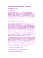
4.2.9 Footing Over Turning
The resistance of a column footing to overturning is
dependent on the weight of the footing and pier, if any,
the weight of soil overburden, if any, and the length of
Fig. 4.19 Development Lengths
the footing in the direction of overturning. During
construction the overburden, backfill, is often not pres-
ent and thus is not included in this overturning calcula-
tion.
Shown in Figure 4.11 is a footing subjected to an
overturning moment.
The overturning resistance equals the weight, W
times the length, L divided by two, i.e.:
Eq. 4-21
where
= 0.9
W = P1+P2 + P3
P1 = the weight of any superimposed loads, kips
P2 = the weight of the pier, if any, kips
P3 = the weight of the footing, kips
After determining each of the individual design
strengths, the lowest bending moment strength can be
compared to the required bending moment to determine
the cantilevered column's suitability.
Example 4-1:
Determine the overturning resistance of a Wl2X65, free
standing cantilever column. Foundation details are
shown in Figure 4.20, and base plate details are shown in
Figure 4.21.
Given:
Leveling Nuts and Washers
4-3/4" ASTM A36 Hooked Anchor Rods with 12"
Embedment and 4" Hook
Pier 1'-4" x 1'-4" with 4 - #6 Vert, and #3 Ties @ 12" o/c
Footing 6'-0" x 6'-0" x l'-3"
18
© 2003 by American Institute of Steel Construction, Inc. All rights reserved.
This publication or any part thereof must not be reproduced in any form without permission of the publisher.
Fig. 4.20 Foundation Detail
Failure Mode 2: Base Plate Failure
Case B: Inset Anchor Rods - Weak Axis Capacity.
Based on the weld pattern and the geometry provided:
(See Figure 4.12)
Fig. 4.21 Base Plate Detail
No Overburden
Material Strengths:
Plates: 36 ksi
Weld Metal: 70 ksi
Reinforcing Bars: 60 ksi
Concrete: 3 ksi
Solution:
Failure Mode 1: Weld Design Strength
Compute (Neglecting Web Weld):
Failure Mode 3: Rupture of Anchor Rods
where
Failure Mode 4: Anchor Rod Buckling (Does not gov-
ern). (See Section 4.2.4.)
Failure Mode 5: Anchor Rod Nut Pull Through (Use
proper washers to eliminate this failure mode.)
19
© 2003 by American Institute of Steel Construction, Inc. All rights reserved.
This publication or any part thereof must not be reproduced in any form without permission of the publisher.
Failure Mode 6: Anchor Rod Pullout
= 628
in.
2
Check Pier Area:
A
e
= 16(16) = 256 in.
2
(Controls)
Note that edge distance will not control.
Check Hook Bearing Strength:
(Eq. 4-14)
= 2(0.7)(0.85)(3000)(0.75)(4)
= 10.7 kips
= 21.4 kips for two rods (Controls)
(Eq. 4-15)
= 8.9ft kips
Failure Mode 7 : Anchor Rod Push Out (Does not oc-
cur with pier.)
Failure Mode 8 : Pier Bending Resistance
Determine the depth of the compression area:
Failure Mode 9: Footing Overturning
(Eq.4-21)
where
0.9
W = P1+P2 + P3
P1 = 65(40)7 1000 = 2.6 kips (Column)
P2 = 0.15(1.33)1.33(3) = 0.8 kips (Pier)
P3 = 0.15(1.25)6(6) = 6.75 kips (Footing)
W = 10.15 kips, L = 6ft.
0.9(10.15)(6/2) = 27.4 ft. - kips
Comparing the above failure modes, the design moment
strength is 8.9 ft kips. The governing failure mode
would be anchor rod pull out.
Example 4-2:
Repeat Example 4-1 using outset anchor rods with em-
bedded nuts.
Increase the pier size to 24" x 24" to accommodate the
base plate. Increase the vertical reinforcement to be
8—#6
bars.
The
distance
from
the
anchor
rod to the
flange tip, L equals 2.83 in.
BasePlate 1" x 20" x l'-8"
= 60,000(2)(0.44)/0.85(3000)(16)
=
1.294
in.
C = 0.85f'
c
a
= 0.85(3000)(16)(1.294)71000
= 52.8 kips
= 52.8(13.75-1.294/2)
= 58 ft kips
Check Reinforcing Development length:
Req'd length in footing:
C(d-a/2) = 692 in kips (Eq. 4-17)
For the straight bars (#6 bars and smaller) in the pier:
20
(Eq. 4-5)
Failure Mode 2: Base Plate Failure
b
e
= 2L =
5.66
in. > 5.0 in.
Fig. 4.23 Base Plate Detail
Solution:
Failure Mode 1: Weld Design Strength
kips (Same as Example 4-1)
© 2003 by American Institute of Steel Construction, Inc. All rights reserved.
This publication or any part thereof must not be reproduced in any form without permission of the publisher.
Fig. 4.24 Base Plate Yield Line
= (0.9)(5)(l)
2
(36)/[(4)(5)]
= 16.2 kips
= (0.75)(0.9)(70)(.707)(5/16)(2)
= 20.9 kips
(Eq. 4-6)
(Eq.
4-7)
= (0.9)(50)(.221)(1)
1.5
- 9.94 kips (Controls)
= 2(9.94)( 16) = 318 in kips
= 26.5ft kips
Failure Mode 3: Rupture of Anchor Rods
(Eq. 4-8)
14.4 kips/rod ( Same as Example 1)
(Eq.4-11)
= 2(14.4)( 16)= 461 in kips
= 38.4 ft kips
Failure Mode 4: Anchor Rod Buckling (Does not gov-
ern)
Failure Mode 5: Anchor Rod Nut Pull Over (Use proper
washers)
Failure Mode 6: Anchor Rod Pull Out
(Eq. 4-13)
21
By inspection the pier area will control.
Check Pier Area:
A
e
= 20(20) = 400 in.
2
(Eq. 4-12)
= 2102 in kips (Eq. 4-15)
= 175 ft kips
Failure Mode 7: Anchor rod "push through" (Does not
occur due to pier)
Failure Mode 8: Pier Bending Resistance
Determine the depth of the compression area:
a = F
y
A
s
/.85f'
c
b
= 60,000(2)(0.44)/0.85(3000)(24)
= 0.863 in.
C = 0.85f
c
ab
= 0.85(3000)(0.863)(24)/1000
52.8 kips
(Eq.4-17)
C(d-a/2)
= 52.8(21.75-0.863/2)
= 1126 in kips
= 94 ft kips
Check Reinforcing Development length: (Same as Ex.
4-1)
Failure Mode 9: Footing Overturning:
where
(Eq.4-21)
0.9
W = P1+P2 + P3
P1 = 65(40) / 1000 = 2.6 kips (Column)
P2 0.15(2)(2)(3)= 1.8 kips (Pier)
P3 = 0.15(1.25)(6)(6) = 6.75 kips (Footing)
W = 11.15 kips
Comparing the above failure modes, the design moment
strength is 26.5 ft kips. The governing failure mode
would be base plate failure.
0.9(11.15)(3) = 30.2 ft kips
=
=
© 2003 by American Institute of Steel Construction, Inc. All rights reserved.
This publication or any part thereof must not be reproduced in any form without permission of the publisher.
Example 4-3:
Repeat Example 4-1, using the Tables provided in the
Appendix.
Solution:
Failure Mode 1: Weld Design Strength
From Table 1, for a W12x65
Failure Mode 2: Base Plate Failure
From Table 2, for a W12x65 with an anchor rod spacing
of 5"x5", and abase plate 1"x13"x13"
Failure Mode 3: Rupture of Anchor Rods
From Table 5, for a 3/4" A36 anchor rod the tension ca-
pacity, equals 14.4 kips, thus from:
where
d = 5"
2(14.4)(5)= 144 in kips
12 ft kips
Failure Mode 4: Anchor Rod Buckling
(Does not govern.)
Failure Mode 5: Anchor Rod Nut Pull Over
To prevent pull over it is suggested that
3/16"x1-1/2"x1-1/2" plate washers be used.
Failure Mode 6: Anchor Rod Pull Out
From Table 10 the concrete pullout design strength for
the 3/4 in. anchor rods spaced 5 inches apart and em-
bedded 12 inches is 57.7 kips/rod. Thus, the total pull-
out design strength for the two rods is 115.4 kips.
Check the design strength based on pier area.
Since hooked rods are used the additional check for
hook straightening must be made.
22
= 2(6.5)(5)/12 = 5.4 ft kips
This illustrates the importance of providing sufficient
clear cover or adding the nut as shown in Figure 4.17.
Example 4-4:
Repeat Example 4-2, using the Tables provided in the
Appendix.
Solution:
Based on the above calculation the overturning resis-
tance is 8.9 ft kips and is based on anchor rod pullout.
It should be noted that concrete punch out of the anchor
rods is not a failure mode because of the existence of the
concrete pier. To illustrate the use of the tables relative
to punch out, determine the overturning resistance with
no pier. The anchor rods have a 3 inch clearance from
the bottom of the footing.
From Table 14, for the 3/4 in. anchor rods on a 5 in. by 5
in. grid 6.5 kips per rod.
Determine the design strength:
From Table 6, the tension design strength for a 3/4 in.
rod with a 4 in. hook is 10.7 kips. Therefore the moment
resistance is controlled by straightening of the hooked
rods. The moment resistance:
= 2(10.7)(5)=107in kips
= 8.9 ft kips (controls)
Failure Mode 7: Anchor Rod "Push Out" (Does not oc-
cur due to pier.)
Failure Mode 8: Pier Bending Resistance
The reinforcement ratio for the 16"x16" pier with 4-#6
bars equals 4(0.44)(100)/(16)
2
= 0.69%.
From Table 18 the bending design strength for a pier
with 0.5% reinforcing equals 51.4 ft kips.
The development length of the reinforcing must also be
checked. From Table 20, for #6 hooked bars the devel-
opment length is 12 inches. Therefore o.k. For the
straight bar the development length is 33 inches, there-
fore o.k.
Failure Mode 9: Footing overturning
From Table 19, the overturning resistance for the
6'-0"x6'-0"x1'-3"
can be
conservatively
(not
including
the weight of the column and pier) based on the table
value for a 6'-0"x6'-0"x 1-2" footing.
18.9ft kips
© 2003 by American Institute of Steel Construction, Inc. All rights reserved.
This publication or any part thereof must not be reproduced in any form without permission of the publisher.
Failure Mode 1: Weld Design Strength
Same as Example 3.
41.7ft kips
Failure Mode 2: Base Plate Failure
From Table 3, 26.5 ft kips
Failure Mode 3: Rupture of Anchor Rods
From Table 5, = 14.4 kips
= 2(14.4)(16) = 461 in kips
= 38.4 ft kips
Failure Modes: 4 and 5
Same as Example 3.
Failure Mode 6: Anchor Rod Pull Out
From Table 10, for the 3/4 in. anchor rods spaced 16"
o.c. with nutted ends, embedded 12 inches:
82.3 kips/rod
= 2(82.3)(16) = 2,634 in kips
= 219 ft kips
Check the design strength based on pier area.
A
e
= 20(20) = 400 in.
2
= 2(65.7)(16) = 2,102 in kips
= 175 ft kips (controls)
Failure Mode 7: Anchor Rod "push through" (Does not
occur because of pier.)
Failure Mode 8: Pier Bending Resistance
The reinforcement ratio for the 24"x24" pier with 8-#6
bars equals:
8(0.44)(100)/(24)
2
= 0.6%
From Table 18, the bending design strength for the pier
is 147.4 ft kips. (Based on a 0.5% reinforcement ratio.)
The development length calculations are the same as in
Example 4-3.
Failure Mode 9: Footing overturning
Same as Example 4-3,
18.9 ft kips
Based on the above calculations the overturning resis-
tance equals 18.9 ft kips and is controlled by footing
overturning.
Since the controlling failure mode was based on conser-
vative values taken from Table 19, and which do not in-
clude the pier or column weight, a more exact calcula-
tion could be performed as in Example 4-1.
Example 4-5
For the column/footing detail provided in Example 4-1,
determine if a 25 foot and a 40 foot tall column could
safely resist the overturning moment from a 60 mph
wind. Use exposure B conditions.
The reduction factor of 0.75 is not applied to the wind
velocity because this check is for an actual expected ve-
locity.
From Example 4-1, the overturning design strength
equals 8.9 ft kips.
Wind Calculations:
F = q
z
G
h
C
f
A
f
where
q
z
= evaluated at height Z above ground
G
h
= given in ASCE 7 Table 8
C
f
= given in ASCE 7 Tables 11-16
A
f
= projected area normal to wind
q
z
- 0.00256K
Z
(IV)
2
K
z
= ASCE 7 Table 6, Velocity Exposure Coefficient
I = ASCE 7 Table 5, Importance Factor
V = Basic wind speed per ASCE 7 para. 6.5.2.
25 foot column calculations:
q
z
= 0.00256(0.46)[(1.0)(60)]
2
= 4.24 psf
F = (4.24)(1.54)(1.5)Af=9.8A
f
psf
A
f
= 12 in. (column width) = 1.0 ft.
F = 9.8(1.0) = 9.8 psf
F
u
= (1.3)(9.8) =12.74 psf
M
u
= F
u
h
2
/2 = (12.74)(25)
2
/2 = 3.981 ft lbs.
= 3.98 ft kips
3.98
< 8.9
o.k.
40 foot column calculations:
23
© 2003 by American Institute of Steel Construction, Inc. All rights reserved.
This publication or any part thereof must not be reproduced in any form without permission of the publisher.
Would the columns described in Example 4-5 safely
support a 300 pound load located 18 inches off of the
column face?
Example 4-6
Factored load:
4.3 Tie Members
During the erection process the members connect-
ing the tops of columns are referred to as tie members.
As the name implies, tie members, tie (connect) the
erected columns together. Tie members can serve to
transfer lateral loads from one bay to the next. Their
function is to transfer loads acting on the partially
erected frame to the vertical bracing in a given bay. Tie
members also transfer erection loads from column to
column during plumbing operations. Typical tie mem-
bers are wide flange beams, steel joists and joist girders.
Since tie members are required to transfer loads,
their design strength must be evaluated. Strength evalu-
ation can be divided into three categories:
A. Tensile Strength
B. Compressive Strength
C. Connection Strength
4.3.1 Wide Flange Beams
Tensile Design Strength
The tension design strength of any wide flange
beam acting as a tie member will typically not require
detailed evaluation. The design strength in tension will
24
almost always be larger than the strength of the connec-
tion between the tie member and the column. Thus, the
tie member will not control the design of the tie. If the
tensile design strength of a tie member must be deter-
mined, it can be determined as the lesser value of the fol-
lowing:
For yielding in the gross section:
For fracture in the net section:
where
effective net area, in.
2
gross area of member, in.
2
specified minimum yield stress, ksi
specified minimum tensile strength, ksi
nominal axial strength, kips
Compression Design Strength
For compression loading wide flange tie beams can
buckle since they are not laterally supported. Shown in
Table 4.1 are buckling design strengths for the lightest
wide flange shapes for the depths and spans shown in the
Table. These values cannot exceed the connection value
for the type of connection used.
Span
(ft.)
20
25
30
35
40
45
50
Depth
(in.)
14
16
18
21
24
27
30
Compression
Design Strength
(kips)
20
20
25
25
25
60
65
Table 4.1 Wide Flange Design Buckling
Strengths
The compression design strengths for specific wide
flange beams can be determined from the column equa-
tions contained in Chapter E of the AISC Specifications
and the design aids of the LRFD Manual Part 3.
Connection Design Strength
Common connections consist of:
From Example 4-1, the overturning design strength
equals 8.9 ft kips.
© 2003 by American Institute of Steel Construction, Inc. All rights reserved.
This publication or any part thereof must not be reproduced in any form without permission of the publisher.
Connection
Type
Beams on Columns
1/4 in. Framing Angles
5/16 in. Framing Angles
3/8 in. Framing Angles
1/4 in. Single-Plate
Shear Connections
3/8 in. Seat
Design
Strength
(kips)
30
10
15
22
30
30
Controlling
Element
Bolts
Framing
Angles
Framing
Angles
Framing
Angles
Bolts
Bolts
Span
(ft.)
20
25
30
35
40
45
50
Joist
Desig-
nation
10K1
14K1
18K3
20K4
20K5
26K5
28K7
Rows of
Bridging
2
2
3
3
4
4
4
Allowable
Load
(kips)
6.0
4.0
4.0
3.5
4.0
4.0
4.0
Span
(ft.)
20
25
30
35
40
45
50
Joist
Desig-
nation
10K1
14K1
18K3
20K4
20K5
26K5
28K7
Rows of
Bridging
2
2
3
3
4
4
4
Design
Strength
(kips)
11.0
7.0
7.0
6.0
7.0
7.0
7.0
1. Beams resting on column tops.
2. Framing angle connections.
3. Single-Plate Shear Connections.
4. Seat angles.
Presented in Table 4.2 are connection design
strengths for these connections. These strengths are
based on the installation of two 3/4" diameter A325
bolts snug tight in each connection. The controlling ele-
ment is also shown.
(LRFD) are shown in Table 4.3a for several spans with
the joist sizes as shown. Provided in Table 4.3b are the
service load (ASD) values.
Table 4.3a Joist Compression Design Strength
Table 4.3b Joist Compression Allowable Load
Compressive design strengths for other spans and
joist sizes can be obtained from the joist supplier.
Connection Strength
Tie joists are typically connected to column tops us-
ing two ½-inch A307 bolts. Many erectors also weld
the joists to their supports using the Steel Joist Institute's
minimum weld requirements (two
1
/
8
-inch fillet welds
one inch long). Since most joist manufacturers supply
long slotted holes in the joist seats the welding is re-
quired to hold the joists in place. The design shear
strength for the two
1
/
8
-inch fillet welds is 7.4 kips,
based on using E70 electrodes.
It should be remembered that if the connections are
not welded a considerable displacement may occur be-
fore the bolts bear at the end of the slot.
The design shear strength for other weld sizes can
be determined from the AISC LRFD Specification. For
E70 electrodes the design shear strength per inch of
weld length can be calculated by multiplying the fillet
weld size in sixteenths by 1.392.
Table 4.2 WF Connection Strengths
4.3.2 Steel Joists
Tensile Strength
As for the case of wide flange beams the tensile de-
sign strength for a tie joist will generally not require
evaluation. The connection of the tie joist to the column
is almost always weaker than the tensile design strength
for the joist. If one wants to evaluate the tensile design
strength, it can again be determined from the equation:
It is suggested that only the top chord area be used
for A in the calculation. The area can be determined by
contacting the joist supplier or by physically measuring
the size of the top chord. The yield strength of K and LH
series joists top chords is 50 ksi.
Compressive Strength
Because the compressive design strength of an un-
bridged K-series joist is low, unbridged K-series joists
should not be relied upon to transfer compression forces
from one bay to the next. The unbridged strength is gen-
erally in the 700 to 800 pound range. Once the joists are
bridged they have considerably greater compressive
strength. Approximate compressive design strengths
25
© 2003 by American Institute of Steel Construction, Inc. All rights reserved.
This publication or any part thereof must not be reproduced in any form without permission of the publisher.
4.3.3 Joist Girders
Tensile Strength
The same comments apply to joist girders as do for
joists acting as tension ties. Connection strengths will
again typically control the design.
Compressive Strength
The design compressive strength of joist girders
can be determined from the AISC LRFD Specification
column equations. Joist girders should be considered as
laterally unbraced until the roof or floor deck has been
secured to the joists. Joists which are not decked may
supply some lateral bracing to the joist girder but the
amount of support cannot be readily determined.
Shown in Table 4.4a are design compressive
strength (LRFD) values for joist girders with the top
chord angles shown. Provided in Table 4.4b are the ser-
vice load (ASD) values. In all cases the minimum avail-
able thicknesses of the angles has been assumed in cal-
culating the values provided in the table.
Connection Strength
Tie joist girders are typically connected to column
tops using two
3
/
4
-inch A325 bolts. The minimum size
SJI welds consist of two ¼-inch fillet welds 2 inches
long. Long slotted holes are generally provided in the
joist girder seats as in the case of joists. The design shear
strength for the two ¼-inch fillet welds is 29.6 kips.
Table 4.4b Joist Girder Service Load
Buckling Strengths (kips)
Example 4-7: (Service Load Design)
This example is done with service loads for easy com-
parison to Example 5-1.
Given: One frame line braced with permanent bracing.
Bays:
6
bays
at
40'-0"
Transverse
bay:
40'-0"
to one
side
of
frame
Have
height:
25'-0"
Tie beams: W18X35
Girders: W24X55
Joists: 22K9 @5'-0" o.c.
Columns: W8X31
Permanent bracing: 2(2) < 3 X 3 ½ X¼ w/(4)
" dia. A325N Bolts
Permanent brace force: 38 kips
Wind speed: 75 mph
Exposure: B
Determination of wind load:
From ASCE 7 Table 4:
F = q
z
G
h
C
f
A
f
Eq.5-5
where
q
z
= evaluated at height Z above ground
G
h
= given in ASCE 7 Table 8
C
f
= given in ASCE 7 Tables 11-16
A
f
= projected area normal to wind
q
z
= 0.00256K
Z
(IV)
2
Eq. 3-2
K
z
= ASCE 7 Table 6, Velocity Exposure Coefficient
I = ASCE 7 Table 5, Importance Factor
V = Basic wind speed per ASCE 7 para. 6.5.2.
Per the proposed ASCE Standard "V" can be reduced
using the 0.75 factor for an exposure period of less than 6
weeks.
26
Table 4.4a Joist Girder Design Buckling
Strengths (kips)
4.4 Use of Permanent Bracing
The design procedure for temporary bracing can be ap-
plied to permanent bracing used as part of the temporary
bracing scheme. It involves the determination of a de-
sign lateral force (wind, seismic, stability) and con-
firmation of adequate resistance. The design procedure
is illustrated is the following example.
Span
ft.
30
35
40
45
50
55
60
Top
21/2
3
2
2
1
1
-
-
Chord
3
6
4
3
2
2
2
-
Angle
31/2
12
9
7
5
4
4
3
Leg Length, (in.)
4
18
13
10
8
6
5
4
5
43
32
24
19
16
13
11
6
74
55
42
33
27
22
19
Span
ft.
30
35
40
45
50
55
60
Top Chord
2
½
3
1.8 3.5
1.2 2.5
1.2 1.8
0.6 1.2
0.6 1.2
-
1.2
- -
Angle Leg Length, (in.)
3
½
4
7.1
10.6
5.3 7.6
4.1 5.9
2.9 4.7
2.5 3.5
2.5 2.9
1.8 2.5
5 6
25.3 43.5
18.8 32.4
14.1 24.7
11.2 19.4
9.4 15.9
7.6
12.9
6.5
11.2
¾
© 2003 by American Institute of Steel Construction, Inc. All rights reserved.
This publication or any part thereof must not be reproduced in any form without permission of the publisher.