Erection Bracing of Low-Rise Structural Steel Buildings phần 7 potx
Bạn đang xem bản rút gọn của tài liệu. Xem và tải ngay bản đầy đủ của tài liệu tại đây (107.6 KB, 10 trang )
Fig. 7.2 Initial Braced Box
Fig. 7.3 Build Out from Initial Box
57
© 2003 by American Institute of Steel Construction, Inc. All rights reserved.
This publication or any part thereof must not be reproduced in any form without permission of the publisher.
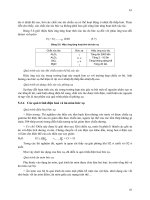
Fig. 7.4 Build Out from Initial Box, Continued
Fig. 7.5 Build Out from Initial Box, Continued
58
© 2003 by American Institute of Steel Construction, Inc. All rights reserved.
This publication or any part thereof must not be reproduced in any form without permission of the publisher.
REFERENCES
1. "American Society of Civil Engineers - Minimum
Design Loads for Buildings and Other Structures",
ASCE7/ANSI A58.1-1993, American Society of
Civil Engineers, New York, New York
2. "Building Code Requirements for Masonry Struc-
tures", ACI 530, 1992, American Concrete Insti-
tute, Detroit, Michigan
3. "Building Code Requirements for Reinforced
Concrete", ACI 318, 1995, American Concrete
Institute, Detroit, Michigan
4. "Code Requirements for Nuclear Safety Related
Concrete Structures", ACI 349-90, "Appendix B
- Steel Embedments", American Concrete Insti-
tute, Detroit, Michigan, 1990
5. "Design Loads for Buildings" German Industrial
Standard 1055, 1986, German Institute for Stan-
dards, Berlin, Germany
6. "Design Loads on Structures During Construc-
tion", proposed American Society of Civil Engi-
neers Standard, 6/95 Draft, American Society of
Civil Engineers, New York, New York
7. DeWolf, John T. and Ricker, David T., "Column
Base Plates", AISC Steel Design Guide Series, No.
1, 1990, American Institute of Steel Construction,
Chicago, Illinois
8. "Diaphragm Design Manual", Second Edition,
Steel Deck Institute, Inc., Canton, Ohio, 1987
9. "Falsework Manual", State of California, Depart-
ment of Transportation, Sacramento, California
10. Fisher, James M., "Industrial Buildings - Roof to
Column Anchorage", AISC Steel Design Guide
Series, No. 7, 1993, American Institute of Steel
Construction, Chicago, Illinois
11. Fisher, James M. and West, Michael A., "Erection
Bracing of Structural Steel Frames", Proceedings,
National Steel Construction Conference, Ameri-
can Institute of Steel Construction, 1995
12. "Low Rise Building Systems Manual", 1986, Met-
al Building Manufacturers Association, Cleve-
land, Ohio
13. "Manual of Steel Construction - Volume II -Con-
nections", ASD, 9th Edition/LRFD, 1st Edition,
American Institute of Steel Construction, Chica-
go, Illinois, 1992
14. "Manual of Steel Construction - Load and Resis-
tance Factor Design", Vols. I and II, 2nd Edition,
59
American Institute of Steel Construction, Chica-
go, Illinois, 1994
15. "Seismic Provisions for Structural Steel Build-
ings", 1992, American Institute of Steel Construc-
tion, Chicago, Illinois
16. "Standards for Load Assumptions, Acceptance
and Inspections of Structures", 1956, No. 160,
Swiss Association of Engineers and Architects,
Zurich, Switzerland
17. "Uniform Building Code", Volumes 1-3,1994, In-
ternational Conference of Building Officials,
Whittier, California
18. "Wind Forces on Structures", ASCE Transactions,
Paper No. 3269, American Society of Civil Engi-
neers, New York, New York
19. "Wire Rope Users Manual", 3rd Edition, Wire
Rope Technical Board, Woodstock, Maryland,
1993
© 2003 by American Institute of Steel Construction, Inc. All rights reserved.
This publication or any part thereof must not be reproduced in any form without permission of the publisher.
Acknowledgements
The authors wish to thank the American Institute of
Steel Construction for funding the preparation of this
Guide and the members of the AISC Committee on
Manuals, Textbooks and Codes for their review of the
Guide and their useful comments. Appreciation is due
to Stephen M. Herlache for his assistance in preparing
the many Tables and to Carol T. Williams for typing the
manuscript.
60
© 2003 by American Institute of Steel Construction, Inc. All rights reserved.
This publication or any part thereof must not be reproduced in any form without permission of the publisher.
shown. A concrete strength of 3000 psi is used. A
clear cover of 3 inches under the nut or hook of the an-
chor rod is used to determine the push through values
shown.
Tables A-15, A-16 and A-17 Compression Resis-
tance of Two Anchor Rods Based on
Concrete Push Out
Tables A-15, A-16 and A-17 are identical to Table
A-14 with the exception that clear covers of 6, 9 and
12 inches are used respectively.
Table A-18 Concrete Pier Bending Resistance
Bending design strengths are provided for the data
shown in the Table. Eq. 4-17 is used with a concrete
strength of 3000 psi to determine the listed values.
Table A-19 Concrete Footing Overturning Resis-
tance
Overturning resistances are provided for the foot-
ing sizes shown in the Table. The values are based on
Eq. 4-21. Only the dead weight of the footing is used
in determining the values.
Table A-20 Reinforcing Bar Development
Lengths, 3000 psi
The required development length for hooked and
straight reinforcing bars are shown in Table A-20.
Eqs. 18,19 and 20 with a concrete strength of 3000 psi
are used to determine the development lengths.
Table A-21 Reinforcing Bar Development
Lengths, = 4000 psi
Table A-21 is identical to Table A-20 with the ex-
ception that a f
c
of 4000 psi is used in the calculations.
Table A-22 Dimensions of Type A Anchor Plates
and Welds
This table provides plate height, thickness and fil-
let weld size for an A36 plate Type A, for the cable type
and slopes presented. A plate of this geometry and at-
tachment will develop the cable design force using a
minimum factor of safety of 3 in selecting the cable.
The Type A plate is shown in Figure 5.2.1. The table
data was determined using the calculation method in
Example 5-2.
Table A-23 Allowable Cable Force, Type A Plate
Anchor as Limited by Anchor Rod Ca-
pacity
This table provides the maximum Unfactored cable
force for the parameters presented based on the cal-
culation method and material strengths in Example
5-4.
Table A-24 Dimensions of Type B Anchor Plates
and Welds
This table provides the plate width and thickness
for an A36 plate Type B, for the cable types and slopes
presented. A plate of this geometry will develop the
cable design force using a minimum factor of safety of
3 in selecting the cable. The Type B plate is shown in
Figure 5.2.2. The table data was determined using the
calculation method in Example 5-3.
Table A-25 Allowable Cable Force, Type B Plate
Anchor as Limited by Anchor Rod Ca-
pacity
This table provides the maximum Unfactored cable
force for the parameters presented based on the cal-
culation method and material strengths in Example
5-6.
62
© 2003 by American Institute of Steel Construction, Inc. All rights reserved.
This publication or any part thereof must not be reproduced in any form without permission of the publisher.
MOMENT RESISTANCE,
Table A-l Moment Resistance of Base Plates with
Inset Anchor Rods Based on Weld Strength
63
BASE PLATES WITH INSET ANCHOR RODS
5/16 inch fillet welds
E70XX Electrode
© 2003 by American Institute of Steel Construction, Inc. All rights reserved.
This publication or any part thereof must not be reproduced in any form without permission of the publisher.
Table A-2 Moment Resistance of Base Plates with
Inset Anchor Rods Based on Plate Strength
64
BASE PLATE BENDING RESISTANCE,
WITH INSET ANCHOR RODS
Shape
Anchor
Rod
Spacing
Base Plate
Plan Size
X-X Axis
Plate Thickness
Y-Y Axis
Plate Thickness
© 2003 by American Institute of Steel Construction, Inc. All rights reserved.
This publication or any part thereof must not be reproduced in any form without permission of the publisher.
Table A-2 Moment Resistance of Base Plates with
Inset Anchor Rods Based on Plate Strength
65
BASE PLATE BENDING RESISTANCE,
WITH INSET ANCHOR RODS
Shape
Anchor
Rod
Spacing
Base Plate
Plan Size
X-X Axis
Plate Thickness
Y-Y Axis
Plate Thickness
© 2003 by American Institute of Steel Construction, Inc. All rights reserved.
This publication or any part thereof must not be reproduced in any form without permission of the publisher.
Table A-3 Moment Resistance of Base Plates with
Outset Anchor Rods
66
MOMENT RESISTANCE - OUTSET RODS,
5/16 inch fillet welds
E70XX Electrode
Shape
Rod Pattern
X-X Axis
Plate Thickness
Y-Y Axis
Plate Thickness
© 2003 by American Institute of Steel Construction, Inc. All rights reserved.
This publication or any part thereof must not be reproduced in any form without permission of the publisher.