handbook of die design 2nd edition phần 4 pps
Bạn đang xem bản rút gọn của tài liệu. Xem và tải ngay bản đầy đủ của tài liệu tại đây (1.98 MB, 72 trang )
METALWORKING MACHINERY 215
FIGURE 5-2 Press drive principle: (1) Main shaft. (2) Pinion. (3) Gear. (4)
Gear. (5) Driving belt. (6) Eccentric connection. (7) Connection link. (8) Slide
adjustment. (9) Ram-retaining assembly. (10) Ram. (11) Counterweight.
(Reprinted with permission from Müller Weingarten AG, Germany.)
FIGURE 5-3 Joint mechanism: (1) Fixed point. (2) Connecting link. (3)
Eccenter. (4) Rocker. (5) Gear assembly. (6) Main shaft. (7) Flywheel. (8) Ram
connection. (Reprinted with permission from Müller Weingarten AG, Germany.)
Suchy_CH05.qxd 11/08/05 10:51 AM Page 215
Downloaded from Digital Engineering Library @ McGraw-Hill (www.digitalengineeringlibrary.com)
Copyright © 2004 The McGraw-Hill Companies. All rights reserved.
Any use is subject to the Terms of Use as given at the website.
METALWORKING MACHINERY
5-1-3 Presses, According to Their Construction
Variations due to the construction of presses allow for the distinction, based on types of
press frames, as:
• C-frame presses or gap-frame
• Closed-frame presses or O-frame
C-frame construction is often used with smaller-capacity presses. Their main advantage
lies in the easily accessible work area, which accounts for shorter setup and adjustment
times. This advantage is perhaps outweighed by their faults, mostly attributable to the shape
of their frame, whose construction is likely to suffer from deflection under load. However,
in current machine building, heavy tie rods and other reinforcements are used to secure the
machine’s sturdiness and accuracy.
These two groups of frame-dependent classification can be further divided into presses
with a single column, double column, and pillar-supported presses (Fig. 5-7).
216 CHAPTER FIVE
FIGURE 5-4 Double-column press. (Reprinted with permission from Müller
Weingarten AG, Germany.)
Suchy_CH05.qxd 11/08/05 10:51 AM Page 216
Downloaded from Digital Engineering Library @ McGraw-Hill (www.digitalengineeringlibrary.com)
Copyright © 2004 The McGraw-Hill Companies. All rights reserved.
Any use is subject to the Terms of Use as given at the website.
METALWORKING MACHINERY
METALWORKING MACHINERY 217
FIGURE 5-5 Sectional view of the press mechanism without reduction gears: (1) Frame. (2)
Control valve. (3) Clutch and brake. (4) Flywheel. (5) Clutch and brake. (6) Eccentric shaft. (7) Slide
stroke adjustment. (8) Slide adjustment. (9) Overload safety device. (10) Slide. (11) Clamping block.
(Reprinted with permission from Müller Weingarten AG, Germany.)
Suchy_CH05.qxd 11/08/05 10:51 AM Page 217
Downloaded from Digital Engineering Library @ McGraw-Hill (www.digitalengineeringlibrary.com)
Copyright © 2004 The McGraw-Hill Companies. All rights reserved.
Any use is subject to the Terms of Use as given at the website.
METALWORKING MACHINERY
218 CHAPTER FIVE
FIGURE 5-6 Sectional view of the press mechanism with reduction gears: (1) Frame. (2)
Control valve. (3) Clutch and brake. (4) Flywheel. (5) Clutch and brake. (6) Reduction gearing.
(7) Eccentric shaft. (8) Slide stroke adjustment. (9) Slide adjustment. (10) Overload safety
device. (11) Slide. (12) Clamping block. (Reprinted with permission from Müller Weingarten
AG, Germany.)
Suchy_CH05.qxd 11/08/05 10:51 AM Page 218
Downloaded from Digital Engineering Library @ McGraw-Hill (www.digitalengineeringlibrary.com)
Copyright © 2004 The McGraw-Hill Companies. All rights reserved.
Any use is subject to the Terms of Use as given at the website.
METALWORKING MACHINERY
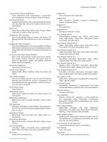
METALWORKING MACHINERY 219
FIGURE 5-7 Press frame types.
FIGURE 5-8 Presses with respect to the horizontal.
Additionally, according to their width-to-height ratio and to the deviation from vertical,
presses can be further categorized as vertical and horizontal presses, inclined or inclinable
presses, and adjustable-bed presses (Fig. 5-8). Figures 5-9 through 5-14 show various
presses. Figure 5-15 shows various drive systems.
The so-called “straight-side” press frames consists of a press bed, which supports the bol-
ster, the crown, two uprights, and the ram (i.e., slide). The uprights form a connection between
the crown and the bed by either being bolted and keyed together, or by tie rods. Straight-side
presses are usually more stiff than gap-frame presses. They additionally do not suffer from
angular deflection, and where vertical deflection under a load is present, it is almost sym-
metrical if their loading is symmetrical too. For these reasons, straight-side presses usually
endanger the punch and die alignment the least.
Another aspect, which affects unfavorably the gap-frame presses equipped with tie rods
is the misalignment caused by the tie rods themselves. These connecting links, in order to
provide the press with the stability and resistance to deflection it needs, have to be tightened
so much that the whole press frame becomes subject to preload. This condition, naturally,
Suchy_CH05.qxd 11/08/05 10:51 AM Page 219
Downloaded from Digital Engineering Library @ McGraw-Hill (www.digitalengineeringlibrary.com)
Copyright © 2004 The McGraw-Hill Companies. All rights reserved.
Any use is subject to the Terms of Use as given at the website.
METALWORKING MACHINERY
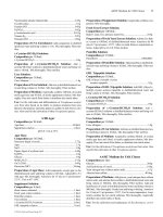
220 CHAPTER FIVE
FIGURE 5-9 Straight-side, high-speed automatic press. Frame: high-tensile strength cast iron, four-piece tie
rod construction. Crankshaft: full eccentric, forged alloy steel. Eight point gibbing. Flywheel or geared. 30–200
tons capacity, 60–500 strokes per minute. (Reprinted with permission from Minster Machine Co., Ohio.)
Suchy_CH05.qxd 11/08/05 10:51 AM Page 220
Downloaded from Digital Engineering Library @ McGraw-Hill (www.digitalengineeringlibrary.com)
Copyright © 2004 The McGraw-Hill Companies. All rights reserved.
Any use is subject to the Terms of Use as given at the website.
METALWORKING MACHINERY
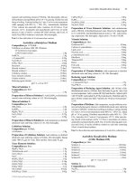
METALWORKING MACHINERY 221
FIGURE 5-10 Straight-side press. Frame: four-piece tie rod construction. Crankshaft: full eccentric, made
of forged alloy steel. Square gibs guide the slide front to back and left to right. Single geared twin drive.
200–1000 tons capacity, up to 150 strokes per minute. (Reprinted with permission from Minster Machine
Co.,Ohio.)
Suchy_CH05.qxd 11/08/05 10:51 AM Page 221
Downloaded from Digital Engineering Library @ McGraw-Hill (www.digitalengineeringlibrary.com)
Copyright © 2004 The McGraw-Hill Companies. All rights reserved.
Any use is subject to the Terms of Use as given at the website.
METALWORKING MACHINERY
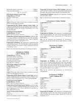
222 CHAPTER FIVE
FIGURE 5-11 C-frame hydraulic press. Frame: welded.
Capacity: 250 to 2500 kN. Working speed up to 8–38 mm/sec.
Maximum pressure 21 to 24.5 MPa. Electrohydraulic controls
by Mannesmann Rexroth. (Reprinted with permission from
OSTROJ, Opava, Czech Republic.)
Suchy_CH05.qxd 11/08/05 10:52 AM Page 222
Downloaded from Digital Engineering Library @ McGraw-Hill (www.digitalengineeringlibrary.com)
Copyright © 2004 The McGraw-Hill Companies. All rights reserved.
Any use is subject to the Terms of Use as given at the website.
METALWORKING MACHINERY
METALWORKING MACHINERY 223
FIGURE 5-12 Open-front power press. Notice the heavy tie rods. (Reprinted with permission from Müller
Weingarten AG, Germany.)
Suchy_CH05.qxd 11/08/05 10:52 AM Page 223
Downloaded from Digital Engineering Library @ McGraw-Hill (www.digitalengineeringlibrary.com)
Copyright © 2004 The McGraw-Hill Companies. All rights reserved.
Any use is subject to the Terms of Use as given at the website.
METALWORKING MACHINERY
forces the ram and the bolster out of parallel which may endanger the tooling along with
the press. The type of press drive used may introduce an additional variation. Figure 5-17
shows a single-point system of drives, in which the rod connecting the ram to the crankshaft
is only one; a two-point system, in which the ram is tied to the crankshaft in two places; and
a four-point system of drive variation, tied at four places. Most often the driving force is
delivered from the upper area of the press, but sometimes even bottom-located driving sys-
tems may be used.
5-2 PARTS OF THE PRESS
Presses consist of several essential components, assembled within the mass of their frames.
Years ago, the presses were simple and straightforward, but also limited in their function.
Today’s presses contain electronic controls, including programming capacities, and altogether,
they can work miracles. These previously rigid and unyielding machines can now be set and
adjusted to provide for any whim and fancy of a demanding toolmaker, shop supervisor, or
engineer.
224 CHAPTER FIVE
FIGURE 5-13 Verson Model ETF-48-9-10TA Electronic Tri-Axis Transfer System with full pro-
grammable servo control for up to 48 in. Transfer stroke, 9 in. Clamp stroke, and 10 in. Lift. Motion para-
meters and die parameters, including the number of finger sensing and die sensing stations, can be
programmed in the “die library menu” and displayed on the Smart Screen operator interface. (Reprinted
with permission from Verson and Danly Division of Enprotech Mechanical Services, Inc., Lansing, MI.)
Suchy_CH05.qxd 11/08/05 10:52 AM Page 224
Downloaded from Digital Engineering Library @ McGraw-Hill (www.digitalengineeringlibrary.com)
Copyright © 2004 The McGraw-Hill Companies. All rights reserved.
Any use is subject to the Terms of Use as given at the website.
METALWORKING MACHINERY
METALWORKING MACHINERY 225
FIGURE 5-14 Danly 2500 ton Automotive Transfer Press, model S4-2500-252-108TF upgraded with
a Verson Electronic tri-axis transfer system, model ETF 45-9-8TA for transferring parts up to 45 in.
between stations at up to 20 strokes per minute. (Reprinted with permission from Verson and Danly
Division of Enprotech Mechanical Services, Inc., Lansing, MI.)
FIGURE 5-15 Drive systems.
Suchy_CH05.qxd 11/08/05 10:52 AM Page 225
Downloaded from Digital Engineering Library @ McGraw-Hill (www.digitalengineeringlibrary.com)
Copyright © 2004 The McGraw-Hill Companies. All rights reserved.
Any use is subject to the Terms of Use as given at the website.
METALWORKING MACHINERY
5-2-1 Press Frame
The frame of the press must be sturdy and rigid in construction, which alone influences the
functional accuracy of the machine. With weak frames, the deflection and later deforma-
tion of the mounting surfaces may occur, producing a subsequent misalignment of main
parts, and possible breakage.
The sturdier and more rigid and stiff the frame is, the less the press mechanisms are
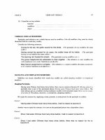
affected by their own function.
226 CHAPTER FIVE
FIGURE 5-16 Various configurations of gibbing used with the box-type guiding system: (a) flat rear
gib and 45° front gib. (b) front and rear 45° gibs, (c) and (d) square gibbing. Allowance for adjustment is
indicated by X. (Reprinted with permission of the Society of Manufacturing Engineers, Tool and
Manufacturing Engineering Handbook, Fourth Edition, Volume 2, Forming, Copyright 1984.)
FIGURE 5-17 Plunger-guided slide design. (From: The FABRICATOR
®
, February 2000, page 77, by
James Landowski. Reprinted with permission from The Croydon Group, Ltd., Rockford, IL.)
Suchy_CH05.qxd 11/08/05 10:52 AM Page 226
Downloaded from Digital Engineering Library @ McGraw-Hill (www.digitalengineeringlibrary.com)
Copyright © 2004 The McGraw-Hill Companies. All rights reserved.
Any use is subject to the Terms of Use as given at the website.
METALWORKING MACHINERY
The material of the frame is another aspect to be evaluated, for cast iron will succumb
to deformation more readily than steel, since its modulus of elasticity is lower.
The best type of frame for press work is the fully enclosed O-type with the fewest open-
ings in the sides and supports. All its flanges and openings should be provided with well-
rounded corners, with no sharp or abrupt lines or connections of any kind.
Press frames are either cast or welded together from segments. Cast frames are used for
smaller presses, their sides sometimes being reinforced with additional plates or tie rods to
increase their sturdiness in operation.
Welded frames may be produced either as a group of various assemblies welded together
to form a single mass or may consist of various segments welded together but finally attached
to each other by other means, the most common method of attachment being that of anchor-
ing with ties, rods, and plates.
5-2-2 Bolster Plate
Bolster plate, sometimes called press table, is positioned on top of the press bed. It is a
heavy plate, ribbed with T slots (to receive T bolts in the assembly of a die), precision-
aligned to the frame with dowel pins.
5-2-3 Ram
The ram, sometimes also called the slide, is the work-delivering part of the press, sliding
up and down, as powered by the driving elements of the machinery.
Proper guidance of the ram, as it moves up and down, is provided by gibs (see Fig. 5-16).
These are attached either to the uprights or to the press frame, in which location they can
easily absorb the thrust force issued by the eccentricity of the drive. Unfortunately, gibs are
also subjected to the load forces generated by the tooling, for which reason they are often
in need of repair and must be replaced quite frequently.
A plunger-guided slide design in combination with gibbing (Fig. 5-17) absorbs the
influence of thrust forces produced by the eccentric drive, with gibs negating the forces
generated by the tooling only. Full-length gibs are required for such an application.
5-2-3-1 Link Motion. Another danger to the mechanical press ran by a flywheel
energy, which is operating on the basis of a fixed speed and force, emerges after the
punches have gone through the pierced material, which happens at the penetration of
approximately 25 to 30 percent of the stock thickness. Once without obstruction and nearly
at the bottom of the stroke, the ram shoots down at a high velocity. Such an increase in its
speed may cause severe shock to both the press and the tooling mounted in it.
To offset this undesirable influence, a link-motion drive was created, capable of controlling
the crankshaft’s output at that particular moment by reducing the slide’s velocity to approxi-
mately 40 percent of its original value near the bottom of the stroke. Yet, even with the veloc-
ity so reduced, the tonnage, the torque, and flywheel energy remain the same. Such adjustment
results in a lesser impact between the upper and lower dies, with reduced repercussions in the
press bearings, and other components. Some operations, such as coining and forming, actually
benefit from such a slowdown, as the slide velocity remains reduced until after the bottom of
the stroke allowing for an extended forming influence on the fabricated material.
A variation of link motion is a draw link, which is used for slowing down the ram in
deep-drawing process. And again, the decrease in the ram’s velocity allows for a better
distribution of material during drawing, which results in lessened tearing, wrinkling, and
other defects related to the drawing process.
METALWORKING MACHINERY 227
Suchy_CH05.qxd 11/08/05 10:52 AM Page 227
Downloaded from Digital Engineering Library @ McGraw-Hill (www.digitalengineeringlibrary.com)
Copyright © 2004 The McGraw-Hill Companies. All rights reserved.
Any use is subject to the Terms of Use as given at the website.
METALWORKING MACHINERY
5-2-4 Press Drive
The power, which is used to drive mechanical presses, is transformed to the ram with the
aid of either:
• Flywheel
• Flywheel and single-reduction gear
• Flywheel and multireduction gear arrangement
In all three types, the flywheel is the storage of energy, being incessantly run by a motor.
During the press stroke, it temporarily slows down because of the transfer of a portion of
its energy to the ram. Driven by the motor, the flywheel gains speed again in time for
another stroke of the press.
Flywheel-only drive is most often used with small dies or where only light blanking is
performed.
5-2-5 Crankshaft
To actuate the slide, crankshafts serve as a link between the press drive and the ram. In their
basis, crankshafts can be of the following types:
• Crank type (crankpin)
• Eccentric
• Cam
• Knuckle joint
• Toggle mechanism
• Drag link
Contrary to all other types of crankshafts, knuckle joints can generate a tremendous
force at the bottom of the stroke. For that reason they are used for compressing operations,
which require short strokes at high pressures.
Toggles are actually levers, linked together. Their function may resemble that of a
knuckle-joint arrangement, but on close observation, toggles display a faster motion, with
longer dwell intervals.
Because drag link mechanisms are slow in motion, they are utilized mostly for drawing
operations.
5-2-6 Clutch And Brake
The clutch, positioned between the flywheel and the press drive mechanism, controls the
timing of the press by engaging and disengaging the drive shaft to the perpetually rotating
flywheel. Clutches can be grouped into three main groups:
• Friction clutches
• Interlocking clutches (positive)
• Eddy-current clutches, operating through the influence of two magnetic fields
Brakes should stop the slide when the clutch is disengaged. Owing to the enormous
mass of the whole machinery, the inertia of all its components can be of tremendous pro-
portions, which calls for a good and dependable braking arrangement.
228 CHAPTER FIVE
Suchy_CH05.qxd 11/08/05 10:52 AM Page 228
Downloaded from Digital Engineering Library @ McGraw-Hill (www.digitalengineeringlibrary.com)
Copyright © 2004 The McGraw-Hill Companies. All rights reserved.
Any use is subject to the Terms of Use as given at the website.
METALWORKING MACHINERY
5-3 PRESS OPERATING PARAMETERS
The energy of the press can be calculated by multiplying its average force by the distance
through which it must be applied. The value of such energy is measured in inch-tons.
The power of the press is the amount of energy which must be exerted during a given
time interval. Its unit of measure is the horsepower.
Some consider the secret of a good die-operating practice as depending on an adequate
amount of pressure, be it the blankholding pressure or the stripping pressure. The selection
and arrangement of springs, along with the selection of the press with adequate tonnage, are
important here.
5-3-1 Tonnage
The value of press tonnage, as given by various press manufacturers, is based on a certain
operating speed of the flywheel. Any difference from the flywheels rpm’s will alter the
energy output of the press.
In a mechanical press, or other stroke-controlled machinery, the tonnage output will
also vary with the position of the ram. When at its lowest, a drop in the press tonnage will
be experienced. When the punching force is needed exactly at the moment the ram is at its
lowest location, and the amount of stroke is comparatively short, the actual press force can
be calculated as follows:
(5-1)
where P
act
is the actual tonnage, at the bottom of the stroke and C
dia
is the diameter of
crankshaft.
This calculation and the information included in Table 5-1 is not applicable to end-
wheel presses equipped with an overhanging crankpin. The preferred range of application
is intended for a forged crankshaft, made of 0.45 percent carbon steel with higher elastic
limits.
5-3-2 Shut Height
Shut height of a press is the space reserved for the accommodation of the die. It is mea-
sured off the top of the bed to the bottom of the slide, with the stroke down and adjust-
ment up.
5-3-3 Stroke
Stroke of the press is the dimensional variation of the slide’s movement during the work
cycle. The stroke must always be greater than the dimensional distance a die has to travel
to operate properly.
5-3-4 Rigidity of Press Construction
One of the main reasons for building the presses as heavy and bulky machines as they are,
is the need for consistent accuracy at all times, independent of the press force variation, or
METALWORKING MACHINERY 229
Suchy_CH05.qxd 11/08/05 10:52 AM Page 229
Downloaded from Digital Engineering Library @ McGraw-Hill (www.digitalengineeringlibrary.com)
Copyright © 2004 The McGraw-Hill Companies. All rights reserved.
Any use is subject to the Terms of Use as given at the website.
METALWORKING MACHINERY
of slightly off center force distribution. The alignment of all press components is very pre-
cise, and an unplanned and unexpected overload to a single part may render the rest of the
machine out of alignment. The main aspect influencing the whole assembly’s working col-
laboration is deflection.
Where a single component will deflect more than the other complementing parts, a dis-
crepancy in fit and subsequently in function will result. Some press components are more
prone to deflection than the others. For example, the shaft, linkage, and ram adjustment–
these all suffer more from deflection than–for example, the press frame. Therefore, it may
be observed that the proneness to deflection is greater in parts with smaller cross-sectional
area, especially where these are being exposed to greater forces.
The rigidity/firmness of press frames could be evaluated as follows:
RF = 4.5(RP) in C-frame presses (5-2)
RF = 15.0(RP) in O-frame presses (5-3)
where RF is the rigidity of the frame and RP is the rigidity of press components.
230 CHAPTER FIVE
TABLE 5-1 Approximate Tonnage of Crankshaft
Capacity at the Bottom of the Stroke
Tons
Crankshaft Single- Double-
dia, in. crank press crank press
1.375 6
1.5 7
1.625 9
1.75 10
1.875 12
2.0 14
2.25 18
2.5 22 22
2.75 26 26
3.0 31 31
3.5 43 43
4.0 56 56
4.5 71 71
5.0 88 88
5.5 106 106
6.0 126 126
6.5 150 150
7.0 180 180
7.5 215 215
8.0 255 255
9.0 345 345
10.0 440 450
11.0 545 650
12.0 665 900
13.0 790 1150
14.0 920 1400
15.0 1060 1700
Suchy_CH05.qxd 11/08/05 10:52 AM Page 230
Downloaded from Digital Engineering Library @ McGraw-Hill (www.digitalengineeringlibrary.com)
Copyright © 2004 The McGraw-Hill Companies. All rights reserved.
Any use is subject to the Terms of Use as given at the website.
METALWORKING MACHINERY
Another harmful effect on the press comes in the form of loss of parallelism between
the die-mounting surface of the ram and that of the press bed. This deviation from parallel
is called angular deviation, or angular distortion, and it is usually expressed in differences
in parallelism between the two surfaces. To properly evaluate this condition, the deviation
must be measured not only in an environment free from press force, but in situations where
a centrally located force is applied to the tested surfaces, as well as an off-center located
force, as shown in Table 5-2.
Another variable affecting the firmness/rigidity of the press, which has a standing effect
on the angular deviation of its mounting surfaces is the material from which all force-
affected parts are made. Generally, it can be stated that the greater the modulus of elastic-
ity of given materials, the greater deflection and issuing angular deviation can be expected.
A less rigid press, made from more elastic materials, will be subject to greater deflection,
up to the point where a considerable portion of its output energy will be wasted on the
deformation work of its elements. The angular deflection further dictates the working tol-
erances in press components’ assemblies. The press tolerance ranges must always be
greater than any dislocation that may result from the lack of parallelism between the press
bed and the ram.
There will always be some amount of detrimental influences already present in the func-
tion of a press that will affect the angular deformation. There may be nonsymmetrical parts
produced in the press, or a progressive diework with less-than-perfect centering of the uti-
lized work force. Other times, the progressive die will be perfectly centered, but not all of
its stations will engage in the predetermined operation at the same time, which, in itself,
will surely shift the center of the utilized press force elsewhere.
Already the differences in material thickness or material hardness may produce a shift
off the central axis of the work force even in perfectly symmetrical parts. Another reason
for work force shift are differences in wear of die segments, which are always followed by
variation in friction, in force usage and its distribution.
METALWORKING MACHINERY 231
TABLE 5-2 Acceptable Angular Deviation Between the Ram and the Press Bed
Type of
angular deviation C-press frame O-press frame
Inches
No press force applied Side-to-side 0.00015 in./linear inch 0.00015 in./linear inch
Front-to-back 0.0003 in./linear inch 0.00015 in./linear inch
Centrally applied force Side-to-side 0.0004 in./linear inch 0.00025 in./linear inch
along the press axis Front-to-back 0.002 in./linear inch 0.00025 in./linear inch
Off-center force applied* Side-to-side 0.002 in./linear inch 0.0005 in./linear inch
Front-to-back 0.001 in./linear inch 0.0005 in./linear inch
Millimeters
No press force applied Side-to-side 0.0045 mm/linear 30 mm 0.0045 mm/linear 30 mm
Front-to-back 0.0090 mm/linear 30 mm 0.0045 mm/linear 30 mm
Centrally applied force Side-to-side 0.0120 mm/linear 30 mm 0.0075 mm/linear 30 mm
along the press axis Front-to-back 0.060 mm/linear 30 mm 0.0075 mm/linear 30 mm
Off-center force applied* Side-to-side 0.060 mm/linear 30 mm 0.0150 mm/linear 30 mm
Front-to-back 0.030 mm/linear 30 mm 0.0150 mm/linear 30 mm
* The off-center force should be located in
1
/
4
of the width of the press (left-to-right), and in
1
/
4
of the depth
(front-to-back). The force should be equal to
1
/
4
of the max. press force.
Suchy_CH05.qxd 11/08/05 10:52 AM Page 231
Downloaded from Digital Engineering Library @ McGraw-Hill (www.digitalengineeringlibrary.com)
Copyright © 2004 The McGraw-Hill Companies. All rights reserved.
Any use is subject to the Terms of Use as given at the website.
METALWORKING MACHINERY
5-3-5 Press Controls
There are quite a few diverse elements involved in the press control. Previously, a single
motor equipped with a starter and a disconnect switch was all that was used. Today, the
complexity and intricacy of press control systems and its components is dependent on
pneumatic, hydraulic, electronics, electrical, and electro-mechanical enhancements. Where
before the operator simply pressed a “Start” button and terminated the press operation by
pressing a “Stop”, a wide range of commands, with sequences of predetermined loops of
operation, supported by an array of limit switches, sensors, relays, air or hydraulic cylinders,
motors, and other components are used (see Fig. 5-18 for the size and complexity of the
control panel).
Programmable logic controllers (PLCs) can nowadays be programmed to respond to every
need of the press operator, or even guide the press in an automatic production environment.
The automatic function of a press can be adjusted to any scenario such a machine can
encounter. Should a valve need be opened to provide for a shift within a press mechanism,
the PLC can be programmed accordingly and the desired shift will occur precisely, on time,
with dependence on the parameters given.
232 CHAPTER FIVE
FIGURE 5-18 Verson 1000 ton Link Drive Blanking Press, model LE4-1000-180-96T
and integrated blanking line control console. Link drive provides fast advance and slow
down during the blanking portion of the stroke to increase production while reducing the
shock associated with the blanking operation. This press is typical of automotive blanking
presses with 12 in. stroke and speed ranging from 20–60 SPM. (Reprinted with permission
from Verson and Danly Division of Enprotech Mechanical Services, Inc., Lansing, MI.)
Suchy_CH05.qxd 11/08/05 10:52 AM Page 232
Downloaded from Digital Engineering Library @ McGraw-Hill (www.digitalengineeringlibrary.com)
Copyright © 2004 The McGraw-Hill Companies. All rights reserved.
Any use is subject to the Terms of Use as given at the website.
METALWORKING MACHINERY
Automatic punching machinery, or numerically-controlled (NC) presses, sometimes also
called “turret presses” are operating on the basis of NC commands, previously contained on a
punched paper, or mylar, tape, today transmitted to the machine via computer network. For
some strange reason, NC presses are sometimes erroneously called CNC presses. In the U.S.
industry, the term “CNC” is reserved to rotating, numerically-controlled machinery, such as
milling centers, lathes, and similar. The meaning of both acronyms, numerically-controlled
(NC) and computerized numerically controlled (CNC), is the same, yet the distinction is kept
to separate the two groups of machines, punch presses as NCs and rotating machines as CNCs.
5-4 PRESSES, ACCORDING TO THEIR
OPERATION
After classifying presses according to various aspects of their construction and use, differ-
entiating them according to the type of their operation is the final point of distinction of this
type of equipment.
5-4-1 Single-Action Press
Single-action presses are used for general press work throughout the industry. The number
of “actions” is given by the number of slides, or rams, operating on a common axis and
mounted within the same frame.
5-4-2 Double-Action Press
A double-action press (Fig. 5-19), as its name implies, has two slides operating along the
same axis yet independent in their movements. Where the first slide may be actuated by the
usual means, the other slide has a different operating arrangement. Quite often, a cam-
dependent movement tied to the first slide’s function is utilized.
METALWORKING MACHINERY 233
FIGURE 5-19 Double-action press.
Suchy_CH05.qxd 11/08/05 10:52 AM Page 233
Downloaded from Digital Engineering Library @ McGraw-Hill (www.digitalengineeringlibrary.com)
Copyright © 2004 The McGraw-Hill Companies. All rights reserved.
Any use is subject to the Terms of Use as given at the website.
METALWORKING MACHINERY
In double-action presses, the second slide, being an additional mechanism, is spaced
around the first, original slide.
A double-action drawing combination has the drawing punch attached to the inner slide
and the blankholder mounted to the second, outer slide. The whole operation can be
adjusted to conform to a sequence, where the blankholder will come down first, retaining
the part to be drawn, and only then the main slide with the drawing punch will follow. On
coming up, the drawing punch leaves first, while the blankholder is still in its place, to
retain the drawn part and prevent it from following up with the tool.
5-4-3 Triple-Action Press
A tripe-action press has three slides, independent in their movement yet assembled within the
same press frame. These presses are quite useful for complex drawing operations, where—
for example—drawing has to be performed in more than one direction. In such a case, the first
drawing punch and the blankholder may draw the part to the appropriate size and dwell to
allow for the third slide’s movement, which pulls the material in another direction.
5-4-4 Multislide Press
Multislide presses may contain several slides assembled within a single press frame, with
their range of operation along various axes. These slides may perform all kinds of work,
either progressive or not. Such an arrangement is actually the same as if several presses
were taken out of their shells and squeezed into a single machine frame.
5-4-5 Hydraulic Press
Hydraulic presses are slower than mechanical presses, but their tonnage force is maintained
constant throughout the stroke, no matter at which position the ram is located. Their total
tonnage may be lowered for fragile die equipment. Double-action hydraulics can have the
tonnage adjusted for both sections, for the punch holder and the blankholder as well.
Hydraulics cannot be overloaded, as they are protected by a combination of two sepa-
rately adjustable relief valves. Die setup is easier, since they do not need to be adjusted for
variation in material thickness. However, their motors must be larger than those of mechan-
ical presses because they have no flywheel to store the energy.
Blanking operations can be detrimental to the hydraulic system, as the shock of punc-
turing the metal endangers its components. Their main range of application is for drawing,
where hydraulics are an excellent choice, mainly because they maintain a constant pressure
on the drawn part, progressing at more adaptable rates. Mechanicals enter the drawn part
full-force and slow down at the bottom of the stroke.
As mentioned previously, repairs of hydraulic presses, even though fewer, are much more
complex and demanding, as the source of their breakdowns is hardly ever detectable visually.
Lately, hydraulics are slowly being accepted as replacements for mechanical presses, in
which capacity they are often utilized for blanking and piercing operations as well. The output
rates of hydraulics improved over the time, with 20 to 40 pieces per minute where produc-
ing parts up to 15 in. [380 mm] in size, and up to 60 parts per minute with 1 to 2 in. [25.5
to 51.0 mm] sizes of products.
Usually, the production being diverted to a hydraulic press consists of parts with
• Lower production rates per each run
• Production known for material thickness inconsistencies
• Parts demanding longer power strokes
234 CHAPTER FIVE
Suchy_CH05.qxd 11/08/05 10:52 AM Page 234
Downloaded from Digital Engineering Library @ McGraw-Hill (www.digitalengineeringlibrary.com)
Copyright © 2004 The McGraw-Hill Companies. All rights reserved.
Any use is subject to the Terms of Use as given at the website.
METALWORKING MACHINERY
• Dies difficult to setup
• Dies in need of variable ram speeds
• Parts with a greater locating accuracy and precise position control
Hydraulics are easier to setup and their changeover time is lower than that of mechani-
cal presses. Where problems with jamming of parts is expected, hydraulics can be of help,
for their built-in overload protection prevents damage to the press by rendering it force-
limited, where needed.
Another advantage of hydraulics is the constant output force, which is available in equal
amounts through any portion of the stroke.
5-4-6 Mechanical-to-Hydraulic Hybrids
It must be admitted that ordinary mechanical presses can nowadays be refurbished to behave
similarly to hydraulics. Equipped with a hydraulic cushion and controlled by the proper
software, the existing mechanical presses can now be turned into versatile mechanical/
hydraulical machines of future pressrooms. This innovative approach, having no competi-
tion worldwide, was developed by Red Stag Automation Inc., WI, who took a pioneering
step ahead by experimenting with cold-forming applications under the restricting aspects of
controlled sensitivity to the pressure and forming characteristics of the material.
Their hydraulic cushion allows for adjustment of the pressure profile by altering the press
tonnage at any given segment of the stroke, in tune with requirements for the actual location
of force application. The resistive force of the hydraulic cushion acts against the press in
such a way that by offering a selective resistance, the press tonnage is being manipulated
with respect for the part being produced. The restrictive force of the cushion can be prese-
lected to be any range between the maximum tonnage of the press all the way to that of zero.
The cushion consists of three tables, each of them equipped with a powerful hydraulic
cylinder at each corner (see Figs. 5-20 and 5-21). The tables can be operated separately, or
as a group. There is an eight-point gibbing arrangement for every table.
METALWORKING MACHINERY 235
FIGURE 5-20 Diagram showing the location of components of a hydraulic die cushion. (Reprinted
with permission from Red Stag Engineering & Automation, Inc., Waupaca, WI 54981.)
Suchy_CH05.qxd 11/08/05 10:52 AM Page 235
Downloaded from Digital Engineering Library @ McGraw-Hill (www.digitalengineeringlibrary.com)
Copyright © 2004 The McGraw-Hill Companies. All rights reserved.
Any use is subject to the Terms of Use as given at the website.
METALWORKING MACHINERY
Their Infinite Control software, originally developed for cold-forming applications,
assists with determination of the force selection needed for a particular product and for a
particular material. Sensing and reporting to the PLC the material resistance encountered
at areas of problem, the software manipulates the press and hydraulic cushions tonnage
along with their timing, thus capable of overcoming the obstacles of material distortion,
defects, or tearing. Suddenly, the material properties, its gauge and grain direction, its com-
position structure, are becoming immaterial and perfect parts are produced with each stroke
of the press.
5-5 OTHER PRESS-ROOM MACHINERY
There is a host of other press-room machinery needed to supplement the function of
presses. Out of the whole array of equipment, several samples were selected for illustration
(see Figs. 5-23 through 5-25).
There are coil straighteners, coil feeds, coil unwinding and coil rewinding equipment,
destacking systems, automated sheet feeders, feeding lines, transporters, robots, tooling
and automation devices, scrap cutters, and others.
As with every manufacturing operation, even feeding of the coil stack or that of blanks
has its areas to watch out for. For example, where a surface finish is not congruent with
the method of feeding, accurate positioning of the material may be jeopardized. Where
slippery surface of the strip can slide off the gripping or feeding devices, discrepancies
of all kinds may emerge. So-called galvanized materials (i.e., dip coated), or surfaces
treated to a lubricant can definitely pose a problem in strip feeding. For these reasons, the
236 CHAPTER FIVE
FIGURE 5-21 Hydraulic cushion for a press bed, consisting of three separate tables
which are either independently or simultaneously operated by hydraulic cylinders, as
guided by the company’s Infinite Control computer software. (Reprinted with permission
from Red Stag Engineering & Automation, Inc., Waupaca, WI 54981.)
Suchy_CH05.qxd 11/08/05 10:52 AM Page 236
Downloaded from Digital Engineering Library @ McGraw-Hill (www.digitalengineeringlibrary.com)
Copyright © 2004 The McGraw-Hill Companies. All rights reserved.
Any use is subject to the Terms of Use as given at the website.
METALWORKING MACHINERY
fabricated material would better be lubricated only after it passes through the feeding
device.
Same with prepainted strips or sheets, or with surfaces to which some cosmetic require-
ments are tied: these can be scratched in the process, marred by stops of the feeding rolls
in the straightener, or damaged when passing through the feeding equipment.
A care must be exercised when straightening or feeding other sensitive materials, such
as stainless steel, high-carbon steel, and some alloys. Here the problem is with the equip-
ment’s rating, which is always geared to processing a mild steel. Where tougher materials
are to be fed or straightened, their yield strength and the shear strength may render the exist-
ing shop equipment useless. Therefore, a careful evaluation of the equipment and its usage
with respect to materials it has to handle must be exercised prior to committing to a pro-
duction of a specific product.
5-5-1 Coil Straightening Equipment
The coil as manufactured in the steel mill and slit to the proper width is either ribbon-
wound around the core or oscillated-wound. A ribbon-wound coil is that, which is wound
on top of itself, over the previously-placed coil surface. Such coils are but a coil-width
wide and where this dimension is below 1 in. [25.4 mm] they may fall apart in handling.
Oscillated-wound coils are placed next to each other, similarly to the thread wound on
a spool. Such coils are wider, as they can accommodate several widths of the slit strip mate-
rial. Once installed in the coil feeding equipment, oscillated coils last much longer without
changing, as for the same diametral size, oscillated coil may contain equal of 20 to 25 ribbon-
wound coils.
Almost every coil that comes to the fabricating plant includes a so-called coil-set, which
is a condition caused by the coil’s wounding process. This is a curvature in coil, which can
make it very difficult to load the beginning of the strip into the press. Therefore, as a step
in-between, coil straighteners are being added to the coil feeding lines (see schematics in
Fig. 5-22 and photo in Fig. 5-23).
METALWORKING MACHINERY 237
FIGURE 5-22 Coil straightening with rollers.
Suchy_CH05.qxd 11/08/05 10:52 AM Page 237
Downloaded from Digital Engineering Library @ McGraw-Hill (www.digitalengineeringlibrary.com)
Copyright © 2004 The McGraw-Hill Companies. All rights reserved.
Any use is subject to the Terms of Use as given at the website.
METALWORKING MACHINERY
238 CHAPTER FIVE
FIGURE 5-23 Straightener with eddy-current drive. (Reprinted with permission from
Minster Machine Co., Ohio.)
Straightening of coils is done by rollers, which are staggered so that a strip material is
being formed either way until it comes out straight, as shown in Fig. 5-22. Here the distance
between the rollers plays an important role, as they must be spaced in such a fashion, as to
support only the elastic deformation of the straightened material.
Usually, five or seven rollers are being used by stamping facilities for coil straightening
purposes. The number of rollers needed to straighten any given material is dictated by the
amount of set the material contains. The diameter of rollers depends on the thickness of the
straightened material with a rule of thumb being the greater the material thickness––the larger
the roller diameter should be.
5-5-2 Coil Feeding Equipment
The two main groups of coil feeding equipment consists of roll feeds and gripper feeds.
Their subgroupings can be assigned with dependence on the source of their power, be it
the press itself, or be it driven by a shop air system, hydraulically, or by a servo-motor
drives.
5-5-2-1 Press-Driven Feeds. The press-driven feeds can be cam feeds, or rack and pin-
ion variations of the same. Of advantage is that their speed of feeding is always synchronized
Suchy_CH05.qxd 11/08/05 10:52 AM Page 238
Downloaded from Digital Engineering Library @ McGraw-Hill (www.digitalengineeringlibrary.com)
Copyright © 2004 The McGraw-Hill Companies. All rights reserved.
Any use is subject to the Terms of Use as given at the website.
METALWORKING MACHINERY
with the function of the press and should the press stop, the feeding of material will stop
too. This synchronization makes such types of feeding arrangements desirable in high-
speed environment, or where unloaders or destackers are being used (Fig. 5-24).
Of disadvantage is their lack of timing adjustment, which does not allow for any
advanced feeding of material to the press until the deepest drawing die in a sequence of
tooling operations, disengages.
Being inherently tied to the press operation, press-driven feeds cannot be persuaded to
jog the strip for threading, unless electrical controls are implemented in their function. But
their gradual acceleration and deceleration of speed, accompanied by no sudden stops or
jumps of the fed material, allows for high-speed indexing with acceptable accuracy.
5-5-2-2 Gripper Feeds. Gripper feeds use a linear motion combined with a pair of
clamps (grippers) for strip advancement, which is limited to a certain given amount only.
In gripper feeds’ function, which depends on a shop air or hydraulic-powered cylinders for
movement and for engaging the material, the feed gripper is used to clamp the material to
be moved. This gripper extends and at the same time, the material-retaining gripper
retracts, releasing the material for movement. The feed pulls the material along using the
feed gripper.
METALWORKING MACHINERY 239
FIGURE 5-24 Tongs feed unit, combined with a press. (Reprinted with permission
from Müller Weingarten AG, Germany.)
Suchy_CH05.qxd 11/08/05 10:52 AM Page 239
Downloaded from Digital Engineering Library @ McGraw-Hill (www.digitalengineeringlibrary.com)
Copyright © 2004 The McGraw-Hill Companies. All rights reserved.
Any use is subject to the Terms of Use as given at the website.
METALWORKING MACHINERY