handbook of die design 2nd edition phần 5 pot
Bạn đang xem bản rút gọn của tài liệu. Xem và tải ngay bản đầy đủ của tài liệu tại đây (1.16 MB, 72 trang )
The punch may often need to be made slightly smaller than the required size of the hole,
as the opening often closes up on its retrieval. Approximately 0.001 in. (0.03 mm) per
diameter reduction in punch size is advisable.
Where rough edges of the punched opening are obtained, a shaving operation may be
needed. Sometimes an alternative material-removing method should be chosen to alleviate
such a problem.
BLANKING AND PIERCING OPERATIONS 287
FIGURE 6-42 Chips within the die.
Suchy_CH06.qxd 11/08/05 10:54 AM Page 287
Downloaded from Digital Engineering Library @ McGraw-Hill (www.digitalengineeringlibrary.com)
Copyright © 2004 The McGraw-Hill Companies. All rights reserved.
Any use is subject to the Terms of Use as given at the website.
BLANKING AND PIERCING OPERATIONS
Suchy_CH06.qxd 11/08/05 10:54 AM Page 288
Downloaded from Digital Engineering Library @ McGraw-Hill (www.digitalengineeringlibrary.com)
Copyright © 2004 The McGraw-Hill Companies. All rights reserved.
Any use is subject to the Terms of Use as given at the website.
BLANKING AND PIERCING OPERATIONS
BLANK CALCULATION
OR FLAT LAYOUT
7-1 THE IMPORTANCE OF FLAT LAYOUT
OR BLANK LAYOUT
The importance of an accurate flat layout has been stressed throughout the preceding text.
In die work and any sheet-metal work in general, the importance of an accurate and dimen-
sionally correct flat layout cannot be overemphasized. Many problems may be avoided if
a full-sized or scaled layout is made first and the part’s manufacture is evaluated on the
basis of it, instead of referring to the bent-up drawing, which, after all, may or may not be
manufacturable.
7-1-1 Flat Layout Development and Calculation
When making a flat layout of a complex part, it always helps to start from a certain side,
one that seems to be basic or the most complex, and unfold the remaining portions bend
after bend.
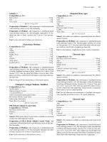
A bracket, shown in Fig. 7-1, is simple enough to serve as an example of the unfolding
technique. First, the A flange may be flattened out to become flush with the vertical portion.
This should be done visually, just by looking at the illustration and imagining the flange
rotating around its pivoting point or an axis of rotation, as if retained by hinges. Such axis of
rotation is always located in the center of bend radius.
Next, the whole vertical segment should be folded down, to become a flat continuation of
the horizontal section, as shown in Fig. 7-2. Such a flattened portion may be sketched, adding
other segments to it as they are unfolded. To provide the flat layout with dimensions, we start
off a single corner and do all dimensioning with regard to that location (for a dimensioned
drawing, see Fig. 7-3). However, when checking the numbers later we should calculate them
off another location and see if the results will be the same. A sample of flat layout for the
bracket is included in Fig. 7-4.
When calculating the dimensions in flat, flange A may be assessed off the top of the
vertical section (see Fig. 7-3) by subtracting its height from the overall dimension, or
3.875 − 2.25 = 1.625 in.
[98.43 − 57.15 = 41.28 mm]
This dimension is included in Fig. 7-3 as a reference, added for flat layout purpose only.
On an actual drawing such a dimension will not be appropriate, as it is already expressed
by the difference between 3.875 and 2.25 in [98.43 and 57.15 mm].
CHAPTER 7
289
Suchy_CH07.qxd 11/08/05 10:55 AM Page 289
Downloaded from Digital Engineering Library @ McGraw-Hill (www.digitalengineeringlibrary.com)
Copyright © 2004 The McGraw-Hill Companies. All rights reserved.
Any use is subject to the Terms of Use as given at the website.
Source: HANDBOOK OF DIE DESIGN
290 CHAPTER SEVEN
FIGURE 7-1 Sample bracket.
FIGURE 7-2 Flat layout preparation.
Since the depth of relief slots is not indicated, it is probably not overly relevant, and in
such a case we can make these cuts as deep as necessary. Usually, a depth equivalent to the
distance measured off the outside surface to the center of the bend radius plus one material
thickness, with up to 2t will suffice as shown in Fig. 7-5.
The width of the relief slot is not specified either, which similarly allows for a variation.
Usually a size of at least one material thickness may suffice, preferably with 1.5t to 2t.
Suchy_CH07.qxd 11/08/05 10:55 AM Page 290
Downloaded from Digital Engineering Library @ McGraw-Hill (www.digitalengineeringlibrary.com)
Copyright © 2004 The McGraw-Hill Companies. All rights reserved.
Any use is subject to the Terms of Use as given at the website.
BLANK CALCULATION OR FLAT LAYOUT
BLANK CALCULATION OR FLAT LAYOUT 291
FIGURE 7-3 Bent-up bracket, with dimensions.
FIGURE 7-4 Bracket, flat layout.
Suchy_CH07.qxd 11/08/05 10:55 AM Page 291
Downloaded from Digital Engineering Library @ McGraw-Hill (www.digitalengineeringlibrary.com)
Copyright © 2004 The McGraw-Hill Companies. All rights reserved.
Any use is subject to the Terms of Use as given at the website.
BLANK CALCULATION OR FLAT LAYOUT
The depth of the relief slot’s bottom must therefore be calculated by using the dimension
1.625 + OuterRad + 1.5t = 1.625 + 0.093 + 0.093 = 1.812 in.
[41.28 + OuterRad + 1.5t = 41.28 + 2.36 + 2.36 = 46.00 mm]
The length of the flange can be calculated by adding the depth of the relief slot measured
off the top of the flange (= 0.187 in. or 4.75 mm) plus the length of the flange (= 0.812 in.
or 20.62 mm) and subtracting one bend allowance, or
0.187 + 0.812 − 0.093 = 0.906 in.
[4.75 + 20.62 − 2.36 = 23.01 mm]
Bend allowance may be taken off the charts in Chap. 8. Table 7-1 is an additional bend
allowance chart, widely used in sheet-metal fabrication, where press-brake bending using
V-dies is prevalent. The chart is added to permit a wider range of comparison of dimen-
sions in flat, which sometimes are advisable to calculate using several different techniques.
To use this chart, outside dimensions of each bend must be added up, with one bend
allowance per bend subtracted from the total. Where the material thickness or bend radius
are not included, such information may be calculated by using the formula
(7-1)
For a so-called sharp bend, the formula will become
(7-2)
where BA = bend allowance
BR = bend radius
t = material thickness
0.45t = 45 percent shrink allowance for a radiused bend
0.50t = 50 percent shrink allowance for a sharp bend
Continuing with the evaluation of a flat layout shown in Fig. 7-4, some dimensions may
be found to double each other by expressing the same information calculated off two dif-
ferent ends of the part. It sometimes pays to include these on the flat layout, especially
BA t t BR BR=− +−
15
2
050 2. (. )
π
BA t t BR BR=− + −
2
2
045 2
π
(. )
292 CHAPTER SEVEN
FIGURE 7-5 Bend allowance determination.
Suchy_CH07.qxd 11/08/05 10:55 AM Page 292
Downloaded from Digital Engineering Library @ McGraw-Hill (www.digitalengineeringlibrary.com)
Copyright © 2004 The McGraw-Hill Companies. All rights reserved.
Any use is subject to the Terms of Use as given at the website.
BLANK CALCULATION OR FLAT LAYOUT
TABLE 7-1 Bend Allowance Chart for Sheet-Metal Material, V-Die Bending
∗
Material
Bend radius
thickness 0.015 0.031 0.062 0.093 0.125 0.156 0.187 0.218 0.250 0.281 0.312 0.343 0.375 0.406 0.437 0.468 0.500
Inches
0.015 0.026 0.033 0.046 0.059 0.073 0.086 0.100 0.113 0.127 0.140 0.153 0.167 0.180 0.194 0.207 0.220 0.234
0.018 0.030 0.037 0.050 0.063 0.077 0.090 0.104 0.117 0.131 0.144 0.157 0.170 0.184 0.198 0.211 0.224 0.238
0.024 0.037 0.044 0.058 0.071 0.085 0.098 0.111 0.125 0.138 0.152 0.165 0.178 0.192 0.205 0.219 0.232 0.246
0.031 0.047 0.053 0.067 0.080 0.094 0.107 0.120 0.134 0.147 0.161 0.174 0.187 0.201 0.214 0.228 0.241 0.255
0.036 0.053 0.060 0.073 0.086 0.100 0.114 0.127 0.140 0.154 0.167 0.180 0.194 0.208 0.221 0.234 0.247 0.261
0.047 0.067 0.074 0.087 0.101 0.114 0.128 0.141 0.154 0.168 0.181 0.195 0.208 0.222 0.235 0.248 0.262 0.275
0.054 0.076 0.083 0.096 0.110 0.123 0.137 0.150 0.163 0.177 0.190 0.204 0.217 0.231 0.244 0.257 0.271 0.284
0.062 0.087 0.093 0.107 0.120 0.134 0.147 0.160 0.174 0.187 0.201 0.214 0.227 0.241 0.254 0.268 0.281 0.295
0.078 0.107 0.114 0.127 0.141 0.155 0.168 0.181 0.194 0.208 0.221 0.235 0.248 0.262 0.275 0.288 0.302 0.315
0.093 0.127 0.134 0.147 0.160 0.174 0.187 0.201 0.214 0.228 0.241 0.254 0.267 0.281 0.295 0.308 0.321 0.335
0.109 0.147 0.154 0.168 0.181 0.195 0.208 0.221 0.235 0.248 0.262 0.275 0.288 0.302 0.315 0.329 0.342 0.356
0.125 0.168 0.175 0.188 0.202 0.215 0.229 0.242 0.255 0.269 0.282 0.296 0.309 0.323 0.336 0.349 0.363 0.376
0.140 0.187 0.194 0.208 0.221 0.235 0.248 0.261 0.275 0.288 0.302 0.315 0.328 0.342 0.355 0.369 0.382 0.396
0.156 0.208 0.215 0.228 0.242 0.255 0.269 0.282 0.295 0.309 0.322 0.336 0.349 0.363 0.376 0.389 0.403 0.416
0.171 0.228 0.234 0.248 0.261 0.275 0.288 0.301 0.315 0.328 0.342 0.355 0.368 0.382 0.395 0.409 0.422 0.436
0.187 0.248 0.255 0.268 0.282 0.295 0.309 0.322 0.335 0.349 0.362 0.376 0.389 0.403 0.416 0.429 0.443 0.456
0.203 0.269 0.276 0.289 0.302 0.316 0.329 0.343 0.356 0.370 0.383 0.396 0.410 0.423 0.437 0.450 0.463 0.477
0.218 0.288 0.295 0.309 0.322 0.336 0.349 0.362 0.375 0.389 0.403 0.416 0.429 0.443 0.456 0.469 0.483 0.497
0.234 0.309 0.316 0.329 0.343 0.356 0.370 0.383 0.396 0.410 0.423 0.437 0.450 0.464 0.477 0.490 0.503 0.517
0.250 0.330 0.337 0.350 0.363 0.377 0.390 0.404 0.417 0.431 0.444 0.457 0.471 0.484 0.498 0.511 0.524 0.538
(Continued)
293
Suchy_CH07.qxd 11/08/05 10:55 AM Page 293
Downloaded from Digital Engineering Library @ McGraw-Hill (www.digitalengineeringlibrary.com)
Copyright © 2004 The McGraw-Hill Companies. All rights reserved.
Any use is subject to the Terms of Use as given at the website.
BLANK CALCULATION OR FLAT LAYOUT
TABLE 7-1 Bend Allowance Chart for Sheet-Metal Material, V-Die Bending
∗
(Continued)
Material
Bend radius
thickness 0.50 0.75 1.50 2.50 3.50 4.00 4.75 5.50 6.25 7.00 8.00 8.75 9.50 10.25 11.00 12.00 13.00
Millimeters
0.40 0.73 0.84 1.16 1.59 2.02 2.23 2.56 2.88 3.20 3.52 3.95 4.27 4.59 4.92 5.24 5.67 6.10
0.50 0.86 0.97 1.29 1.72 2.15 2.36 2.69 3.01 3.33 3.65 4.08 4.40 4.72 5.05 5.37 5.80 6.23
0.63 1.03 1.14 1.46 1.89 2.32 2.53 2.85 3.18 3.50 3.82 4.25 4.57 4.89 5.21 5.54 5.97 6.39
0.80 1.25 1.36 1.68 2.11 2.54 2.75 3.07 3.40 3.72 4.04 4.47 4.79 5.11 5.43 5.76 6.18 6.61
1.00 1.51 1.62 1.94 2.37 2.80 3.01 3.33 3.65 3.98 4.30 4.73 5.05 5.37 5.69 6.01 6.44 6.87
1.20 1.77 1.87 2.20 2.62 3.05 3.27 3.59 3.91 4.23 4.56 4.99 5.31 5.63 5.95 6.27 6.70 7.13
1.40 2.03 2.13 2.45 2.88 3.31 3.53 3.85 4.17 4.49 4.81 5.24 5.57 5.89 6.21 6.53 6.96 7.39
1.60 2.28 2.39 2.71 3.14 3.57 3.79 4.11 4.43 4.75 5.07 5.50 5.82 6.15 6.47 6.79 7.22 7.65
2.00 2.80 2.91 3.23 3.66 4.09 4.30 4.63 4.95 5.27 5.59 6.02 6.34 6.66 6.99 7.31 7.74 8.17
2.20 3.06 3.17 3.49 3.92 4.35 4.56 4.88 5.21 5.53 5.85 6.28 6.60 6.92 7.24 7.57 8.00 8.42
2.80 3.84 3.94 4.26 4.69 5.12 5.34 5.66 5.98 6.30 6.63 7.05 7.38 7.70 8.02 8.34 8.77 9.20
3.00 4.09 4.20 4.52 4.95 5.38 5.60 5.92 6.24 6.56 6.88 7.31 7.63 7.96 8.28 8.60 9.03 9.46
3.50 4.74 4.85 5.17 5.60 6.03 6.24 6.56 6.89 7.21 7.53 7.96 8.28 8.60 8.93 9.25 9.68 10.11
4.00 5.39 5.49 5.82 6.25 6.67 6.89 7.21 7.53 7.86 8.18 8.61 8.93 9.25 9.57 9.89 10.32 10.75
4.50 6.03 6.14 6.46 6.89 7.32 7.54 7.86 8.18 8.50 8.82 9.25 9.57 9.90 10.22 10.54 10.97 11.40
5.00 6.68 6.79 7.11 7.54 7.97 8.18 8.50 8.83 9.15 9.47 9.90 10.22 10.54 10.87 11.19 11.62 12.05
5.50 7.33 7.43 7.76 8.19 8.61 8.83 9.15 9.47 9.79 10.12 10.55 10.87 11.19 11.51 11.83 12.26 12.69
6.00 7.97 8.08 8.40 8.83 9.26 9.48 9.80 10.12 10.44 10.76 11.19 11.51 11.84 12.16 12.48 12.91 13.34
7.00 9.27 9.37 9.70 10.13 10.55 10.77 11.09 11.41 11.73 12.06 12.49 12.81 13.13 13.45 13.77 14.20 14.63
∗
Use the outside dimensions of each bend and subtract the bend allowance shown.
294
Suchy_CH07.qxd 11/08/05 10:55 AM Page 294
Downloaded from Digital Engineering Library @ McGraw-Hill (www.digitalengineeringlibrary.com)
Copyright © 2004 The McGraw-Hill Companies. All rights reserved.
Any use is subject to the Terms of Use as given at the website.
BLANK CALCULATION OR FLAT LAYOUT
where certain locations will have to be constantly recalculated off different ends. These
dimensions may also serve as an efficient way of checking the flat layout, especially where
the same person who drew and calculated it will have to check it and manufacture the part.
The flat length of the flange B should be calculated the same way as described previously.
Here, the difference between the outer edge of the horizontal portion and that of the flange
should be figured starting off the bottom of the relief slot, which should be established first. To
verify the calculation, dimensions off the left edge of the blank should be used.
The bracket, shown in Fig. 7-6 presents a slightly different problem. Here, the flange
A contains an oval indentation for strengthening. Side flanges B
1
and B
2
show sharp-cor-
nered cutouts of considerable size, which may cause problems in bending, because their
bottom edge is located only 1.5t off the center of bend radius. The dimensioned bent-up
drawing of the part and its flat layout are included for study and comparison of results
(see Figs. 7-7 and 7-8).
7-1-2 Phantom Areas
A part in Fig. 7-9 containing so-called phantom areas is shown for evaluation. Phantom areas
are portions of unavailable material, not obvious from the bent-up drawing (see Fig. 7-10).
Only on observation of the flat layout (shown in Fig. 7-11), it becomes clear that it will be
impossible to obtain the shaded corners of the two side flanges from the material given.
A change of either part’s manufacturing process or that of its outline will have to be made.
If the outline must be kept, the manufacturing process can have the two corners welded
on later and sanded smooth—an operation quite expensive, unpractical, and cumbersome.
Some may volunteer to weld both sides to the flat bottom, which will totally defeat the prac-
ticability of die-manufacturing process.
A folded-up drawing of the part with dimensions and its flat layout are included for
personal comparison and study. Note the width of the bottom flat portion being made
0.81 + 0.00/−0.01 in [20.6 + 0.0/−0.2 mm] on the flat layout, in congruence with the
folded-up drawing shown in Fig. 7-10, where a material-thickness wide gap is shown between
BLANK CALCULATION OR FLAT LAYOUT 295
FIGURE 7-6 Support bracket, bent-up part.
Suchy_CH07.qxd 11/08/05 10:55 AM Page 295
Downloaded from Digital Engineering Library @ McGraw-Hill (www.digitalengineeringlibrary.com)
Copyright © 2004 The McGraw-Hill Companies. All rights reserved.
Any use is subject to the Terms of Use as given at the website.
BLANK CALCULATION OR FLAT LAYOUT
296 CHAPTER SEVEN
FIGURE 7-7 Support bracket. Bent-up part with dimensions.
FIGURE 7-8 Support bracket, flat layout.
the bottom and inner walls of the enclosure. The tolerance range in this case depends on several
variables, such as
• Material thickness and its tolerance, especially the increase in thickness
• Tolerance requirements for the 1.0 in. [25 mm] overall width of the part, as shown in
Fig. 7-10.
Suchy_CH07.qxd 11/08/05 10:55 AM Page 296
Downloaded from Digital Engineering Library @ McGraw-Hill (www.digitalengineeringlibrary.com)
Copyright © 2004 The McGraw-Hill Companies. All rights reserved.
Any use is subject to the Terms of Use as given at the website.
BLANK CALCULATION OR FLAT LAYOUT
• The size of permissible gap between the edge of the flat bottom material and the inner
surface of the two side flanges
• Bending operation tolerance range
If changes to the part’s outline were permissible, these are included in Fig. 7-12. In the
first illustration, the sharp corners previously interfering with the middle section of the part
were removed and the relief slot was brought all the way through, on each side. The sec-
ond picture shows the sharp corners respected with the middle section narrowed down to
allow for their procurement.
The design shown in Fig. 7-13 considers the sharp corners as being used for offsetting the
part off a certain surface. Yet, these corners were removed and their function taken over by
the middle shelf, bent down to provide the offset in the location where needed. If shortening
BLANK CALCULATION OR FLAT LAYOUT 297
FIGURE 7-9 Cover, bent-up part.
FIGURE 7-10 Cover, bent-up part with dimensions.
Suchy_CH07.qxd 11/08/05 10:55 AM Page 297
Downloaded from Digital Engineering Library @ McGraw-Hill (www.digitalengineeringlibrary.com)
Copyright © 2004 The McGraw-Hill Companies. All rights reserved.
Any use is subject to the Terms of Use as given at the website.
BLANK CALCULATION OR FLAT LAYOUT
298
FIGURE 7-13 Cover, another design change.
FIGURE 7-11 Cover, flat layout.
FIGURE 7-12 Cover, change of design.
Suchy_CH07.qxd 11/08/05 10:55 AM Page 298
Downloaded from Digital Engineering Library @ McGraw-Hill (www.digitalengineeringlibrary.com)
Copyright © 2004 The McGraw-Hill Companies. All rights reserved.
Any use is subject to the Terms of Use as given at the website.
BLANK CALCULATION OR FLAT LAYOUT
of the middle surface be objectionable, tabs on each side of the flat bottom can be produced,
while the center can be kept at the length needed.
The final idea, presented in Fig. 7-14, makes the sharp corners from the bent-up sides
of each flange. Such a U-bend, called a Dutch bend, can be flattened in the die, which will
press both the surfaces together. This way the so much sought-after sharp corners will be
there, but a material thickness away. The flat layout of this design is presented in Fig. 7-15.
BLANK CALCULATION OR FLAT LAYOUT 299
FIGURE 7-14 Cover, redesigned part.
FIGURE 7-15 Cover, flat layout of redesigned part shown in Fig. 7-14.
Suchy_CH07.qxd 11/08/05 10:55 AM Page 299
Downloaded from Digital Engineering Library @ McGraw-Hill (www.digitalengineeringlibrary.com)
Copyright © 2004 The McGraw-Hill Companies. All rights reserved.
Any use is subject to the Terms of Use as given at the website.
BLANK CALCULATION OR FLAT LAYOUT
FIGURE 7-16 Offset bracket, bent-up part.
7-1-2-1 Offset Bracket Sample. Another phantom area-containing bracket is shown in
Fig. 7-16. Here, the two prongs are located on the same bend line, while the middle prong
is offset backward.
The middle offset prong has two side flanges, each pierced at two places. These flanges,
when observed on the flat layout shown in Fig. 7-17, cannot actually be made, as there is
not enough material for their width.
If these flanges were located higher up, plenty of stock will be available once their loca-
tion exceeds the top edge of the two side prongs. However, let us assume their location is
firm and must remain as such.
There seems to be no chance of producing the material for these flanges from any-
where unless it is taken from the material of the two prongs, as shown in Fig. 7-18A.
Provided the sharp-edged cutout and the difference in width of the prongs’ top will not
impair the overall function of the part, this may become a solution to a given problem.
Where the sharp edge may be objectionable, it may be either rounded or chamfered, as
shown by dotted lines.
Tooling for such a design change will be more costly, for which reason an overall
widening of the relief slot, shown in Fig. 7-18B, may be more advantageous.
300 CHAPTER SEVEN
Suchy_CH07.qxd 11/08/05 10:55 AM Page 300
Downloaded from Digital Engineering Library @ McGraw-Hill (www.digitalengineeringlibrary.com)
Copyright © 2004 The McGraw-Hill Companies. All rights reserved.
Any use is subject to the Terms of Use as given at the website.
BLANK CALCULATION OR FLAT LAYOUT
301
FIGURE 7-17 Offset bracket, flat layout.
FIGURE 7-18 Offset bracket, flat layout variation no. 1.
Suchy_CH07.qxd 11/08/05 10:55 AM Page 301
Downloaded from Digital Engineering Library @ McGraw-Hill (www.digitalengineeringlibrary.com)
Copyright © 2004 The McGraw-Hill Companies. All rights reserved.
Any use is subject to the Terms of Use as given at the website.
BLANK CALCULATION OR FLAT LAYOUT
Naturally even this solution may not suffice, and another alternative has to be sought
after. Shown in Fig. 7-19 is a different method of changing the given design. Here, the top
of the middle prong is extended farther and spread out sideways, the extension being equal
to the offset of two small side flanges, as shown in the folded view.
Such a change may seem to do the job of placing the two-side flanges in an appropriate
location, but at a very steep price, for the part is much higher now with its width increased
as well. Aside from the obvious wastage of material, an additional two bending operations
are included. Also a possible need for two small tabs P may arise, if the two narrow strips-
turned-flanges are to be secured to the body of the middle prong. Such a design is not only
impractical, it is outright clumsy.
In Fig. 7-20 is shown yet another attempt at design change of the given flat layout,
where the relief cuts of the two side prongs have been slanted. It is perhaps a slightly less
practical variation of the Fig. 7-18A and B method. The tool, cutting the angled portion,
may not be narrow enough to miss the corner of each side flange, which may result in an
involuntary and also uneven chamfer of its edge.
The size of the tool should concern us here, as such a large punch may require skipping
an extra station in the progressive die. The other side may need an additional station to skip,
and the final size of the die may be enormous.
Figure 7-20B depicts a halfway method, where the material for side flanges is taken off
the area between the prongs by sinking the flanges into the material of the middle prong.
This solution can be used where the horizontal distance between the flanges, as shown in
Fig. 7-16, can be changed without impairing the function of the part.
The final design change is shown in Fig. 7-21. The compromise presented here
involves a slight narrowing of the side prongs, with a slight narrowing of the two
302 CHAPTER SEVEN
FIGURE 7-19 Offset bracket, flat layout variation no. 2.
Suchy_CH07.qxd 11/08/05 10:56 AM Page 302
Downloaded from Digital Engineering Library @ McGraw-Hill (www.digitalengineeringlibrary.com)
Copyright © 2004 The McGraw-Hill Companies. All rights reserved.
Any use is subject to the Terms of Use as given at the website.
BLANK CALCULATION OR FLAT LAYOUT
303
FIGURE 7-20 Offset bracket, flat layout variation no. 3.
FIGURE 7-21 Final design change.
Suchy_CH07.qxd 11/08/05 10:56 AM Page 303
Downloaded from Digital Engineering Library @ McGraw-Hill (www.digitalengineeringlibrary.com)
Copyright © 2004 The McGraw-Hill Companies. All rights reserved.
Any use is subject to the Terms of Use as given at the website.
BLANK CALCULATION OR FLAT LAYOUT
flanges as well. This will leave enough gap in between for the material of the two side
flanges.
We will need to clean up the area of each gap after producing a knife cut along the prongs’
edges. This cut will totally separate each flange from its side prong, producing a continuous
edge with no tool marks or steps. The prongs may be bent down somewhat by its action,
which can be repaired by pushing them back with a pressure pad.
7-2 DETAILS OF A FLAT LAYOUT
When making a flat layout, there are certain areas where paying attention to the detail saves
a great many headaches later, when the tooling is made in steel. These areas of interest are
mainly corner-relief slots, transitions between radii and straight surface lines, holes and
their location off bends, and the like. Many of these problem-prone areas may be success-
fully produced by a simple adjustment of the manufacturing sequence of operations, but
there are cases where such a solution would not be adequate.
Naturally, the importance of the positioning of parts with regard to the material grain is
vital to the functionability of the product and to its manufacturability as well. Further, a cor-
rect assessment of the part’s burr side and design of tooling in accordance with its location
is of essence.
For example, to place a switch cover with the burr side up may tear the skin of the user,
provided the switch is embedded within the cover plate. A similar effect would be achieved
by reversing the burr side of the binder’s opening-closing lever mechanism or that of any
closure, hardware, and many other items of daily personal and industrial use.
The location of a burr with reference to the functional side of the part may cause the
final product to either make it or break it, as they say. Therefore, a careful observation of
the part and a correct assessment of its surfaces would be of essence where the location of
the burr is not specified on the drawing.
7-2-1 Details of Corners and Relief Slots
In order to eliminate the possibility of sharp corners, some parts have their edges chamfered
or rounded. This in itself seems like a logical solution when considering their functionability,
but to actually produce such a corner is a different story. It is quite easy to chamfer an edge
by using a square tool under 45° angle and hitting each corner prior to blanking its outline.
We already know that we should not attempt to perform such a sequence of operations in
reverse, and to chamfer the corner after the outline is blanked out, since the punch, cutting
with but a small portion of its face total area, will have a tendency to buckling and breakage.
However, rounding of edges of parts is a completely different matter. With large-sized
items, which demand a small, perhaps even dimensionally unspecified corner radius, this
will not be such a problem. These parts may always be touched up individually later. But
with small parts pouring from the die in quantity, a different solution will be needed where
rounding of their corners is required.
As seen in Fig. 7-22A, a radius tool is used to produce a quarter-circle cut, with the rest
of the material being chopped off by a rectangle. No matter which way the sequence of
operations is arranged, a step between the cuts may be produced if the tooling is not sharp
or tight enough, or where the detrimental qualities of the material, such as high ductility or
brittleness, are present.
Where the tools overlap, a step may be produced at either or both ends of the length of
the overlap. This may be even more complicated if punching first with the rectangle and
304 CHAPTER SEVEN
Suchy_CH07.qxd 11/08/05 10:56 AM Page 304
Downloaded from Digital Engineering Library @ McGraw-Hill (www.digitalengineeringlibrary.com)
Copyright © 2004 The McGraw-Hill Companies. All rights reserved.
Any use is subject to the Terms of Use as given at the website.
BLANK CALCULATION OR FLAT LAYOUT
following up with the radius tool. A small sliver of material, shown in the enlarged detail
P, may not be cut off properly. Because of its insignificant size, this little corner may fit
within the tooling tolerance range, and instead of being cut off, it will be squeezed down,
where it will aid in the formation of the burr.
An alternative to detail A cutting is presented in detail C of the same illustration. Here
the whole area is removed by a single punch, shaped to suit the required size and contour.
However, even though the resulting cut will be perfect, a tool like this is highly special-
ized, usable for one particular cut only. Where the other side of the part will need the
same rounding to be produced, another tool—a mirror image of the first one—will have
to be made.
A four-way radius tool, often used in sheet-metal practice for procurement of radii at
various locations, is shown in Fig. 7-22D. We may expect interference and sliver appear-
ance similar to detail P description, where the abrupt edge of this tool encounters another
cut. Perhaps the cheapest way to avoid this happening is to incline the sides of the four-way
radius tool (or any other tool, for that purpose), right after the quarter-circle, as shown in
detail E. Of course, the rectangular cut must be performed first with the radius tool, but
touching up the edge.
Corners of sheet-metal parts may often pose a problem, especially where joining two
flanges together, as seen in Fig. 7-23A. Here the two edges of a box-type shape must be very
close, almost touching. Some may attempt to pattern the relief slots as shown in detail B.
This solution may often be used with different sizes of bend radii, provided the sharp cor-
ner may be removed where it should exceed the shape of the part. A method of replacing
such a complicated relief slot pattern with a single round opening, shown in detail C, may
often be a better solution. The sharp corner will be shifted into another location, with its
size and sharpness dependent on the distance of the round tool off the part’s edge.
Another manufacturing method of producing a corner relief is to offset both cuts slightly
below the bend line, as shown in Fig. 7-23D. Such an arrangement will certainly work well
BLANK CALCULATION OR FLAT LAYOUT 305
FIGURE 7-22 Corner radii.
Suchy_CH07.qxd 11/08/05 10:56 AM Page 305
Downloaded from Digital Engineering Library @ McGraw-Hill (www.digitalengineeringlibrary.com)
Copyright © 2004 The McGraw-Hill Companies. All rights reserved.
Any use is subject to the Terms of Use as given at the website.
BLANK CALCULATION OR FLAT LAYOUT
with parts, where a sharp edge is permissible, and the gap between the two sides can be con-
trolled by the distance of the cutter off the bend line. An alternative of the same joining
method is shown in E, where one side of the box is bent to fit under the other flange.
Face flanges present a slightly different challenge to the avid die or sheet-metal designer.
Here the corner may be finished either by joining two perpendicular flanges or by providing
a 45° cut in the middle, as shown in Fig. 7-24A and D, respectively.
The method of corner finishing depicted in detail A will always display a gap of some
kind, especially where larger bend radii are involved. With large-sized parts, these gaps
may be filled in and ground smooth, but with small, mass-produced items, such a finishing
procedure is highly unreasonable. A 45° cut is more appropriate in a case like this.
The amount of space between the adjoining flanges shown in D may be diminished to a
negligible size by a correct assessment of the depth of relief cut. The variation of such space
will be achieved by moving the peak of the cut with reference to the face bend line, as
shown in E and F.
An easy method of evaluating the gap size is to calculate the exact position of the edge
of each flange and determine the size of the space between them by using basic trigonom-
etry. Naturally, the bend allowance for such a bend must be divided equally between both
sides of a part. Where the peak of a relief cut will end at the bend line, a slight bulging of
the material around that area may be expected after bending.
Sometimes, if the closest possible contact between the two flanges is required, some bend
reliefs are purposely made smaller than necessary, allowing for tearing of the material in bend-
ing. This is done especially with large parts, where these areas may be sanded smooth later on.
7-2-2 Holes Versus Bends
The location of openings with reference to the bend line is of considerable importance in
sheet-metal practice. The metal material, when subjected to stretching and compressing dur-
ing the bending process, has a tendency to extend the shape of a hole, changing its contour
306 CHAPTER SEVEN
FIGURE 7-23 Corner design variations no. 1.
Suchy_CH07.qxd 11/08/05 10:56 AM Page 306
Downloaded from Digital Engineering Library @ McGraw-Hill (www.digitalengineeringlibrary.com)
Copyright © 2004 The McGraw-Hill Companies. All rights reserved.
Any use is subject to the Terms of Use as given at the website.
BLANK CALCULATION OR FLAT LAYOUT
from round to elliptical. This may be prevented where it is possible to bend the part first and
pierce the holes afterward. However, such a work sequence may involve a side action of the
die, utilizing cams, which is not always the most desirable method of solving this problem.
In some cases, the holes in question may be pierced oval in shape, so that when being
tugged upon by the strain of the bending process, their elongation will actually make them
round. See Fig. 7-25.
BLANK CALCULATION OR FLAT LAYOUT 307
FIGURE 7-25 Shape of openings altered by bending.
FIGURE 7-24 Corner design variations no. 2.
Suchy_CH07.qxd 11/08/05 10:56 AM Page 307
Downloaded from Digital Engineering Library @ McGraw-Hill (www.digitalengineeringlibrary.com)
Copyright © 2004 The McGraw-Hill Companies. All rights reserved.
Any use is subject to the Terms of Use as given at the website.
BLANK CALCULATION OR FLAT LAYOUT
The minimal distance of the edge of an opening off the bend should equal 2t, or two mate-
rial thicknesses, measured off the center of the bend radius. In the same way the edge of the
part should be at least two metal thicknesses off the center of the radius, as shown in Fig. 7-26.
Where a sharp corner bend is absolutely necessary, perhaps to serve as a relief for the
corner of an adjoining part, it may be produced by restriking the bent-up part with the inten-
tion of sharpening the inner radius. Since during such a process the material of the edge will
be slightly diminished in thickness, some bulging of the bend line may be needed prior to
the bending operation, as shown in Fig. 7-26D.
7-2-2-1 Relief Openings. To punch relief openings in metal, such as those providing an
access for the assembly tool (see Fig. 7-27), or clearance holes for screws or other inserts,
it pays to make these holes as large as possible. Larger openings not only provide for a pos-
itive relief action, they are not easily affected by any dimensional discrepancy, which in
bent-up parts may sometimes be seen.
Openings where the location of their center with respect to the corresponding part is out-
right questionable, as with segments of large-sized assemblies or constructions, oval holes
should replace rounds, with the longer side of the shape positioned along the path of the
expected dimensional discrepancy (see Fig. 7-27C).
308 CHAPTER SEVEN
FIGURE 7-27 Access openings.
FIGURE 7-26 Location off the bend.
Suchy_CH07.qxd 11/08/05 10:56 AM Page 308
Downloaded from Digital Engineering Library @ McGraw-Hill (www.digitalengineeringlibrary.com)
Copyright © 2004 The McGraw-Hill Companies. All rights reserved.
Any use is subject to the Terms of Use as given at the website.
BLANK CALCULATION OR FLAT LAYOUT
7-2-2-2 Extruded Openings and Bosses The size and depth of extruded shapes should
be calculated the same way a bend would be assessed. After all, that is what these contours
are, when observing their cross-sectional outlines: they are bent-up, sometimes slightly
drawn shapes.
Most extruded openings must first be pierced in order to provide enough space for the
extruding punch, which is to form the edges afterward. To calculate the size of the basic
opening, we must assess the length of the bent-up (or extruded) portion, apply the neces-
sary bend allowance, and subtract the result from the size of the extruded shape, or
d = 2[B − (A + h − BA)] (7-3)
where BA is the bend allowance.
All other values are given in Fig. 7-28.
This calculation does not take into consideration any drawing tendency of the material,
figuring the obtained shape to be attributable strictly to bending.
Often such a calculation may be used when determining the largest possible height h,
obtainable from the smallest possible pierced opening. In such a case, the diametral size of
the original opening with respect to the diameter of the final shape (2B dia.) are the factors
limiting the height of the extruded shape.
Bosses and dimples may be evaluated the same way; however, these indentations often
contain some stretching of material with subsequent thinning of some sections.
7-2-3 Dutch Bends and Joggles
Dutch bends, or 180° bends, are used as hems in sheet-metal practice (Fig. 7-29). Such
bends are actually doubled 90° bends, with the outer surface of the material forming a
whole half circle around the center of the bend. There is almost no bend radius with this
type of bending.
To calculate the size of a hemmed part in flat, the chart shown in Table 7-2 should be
used. Table 7-3 gives the minimal length of hem A.
Joggles are offsets in height, connected by a short piece of angular strip of the same
material, as shown in Fig. 7-30. Joggles are used where an offset for another part of the
assembly is to be provided or where a greater flatness of the actual contact surface is
desired. Joggles may also be used to stiffen the part or to provide for collection of liquids,
in which case they take the shape of a shallow cuplike indentation within the flat surface.
BLANK CALCULATION OR FLAT LAYOUT 309
FIGURE 7-28 Extruded openings.
Suchy_CH07.qxd 11/08/05 10:56 AM Page 309
Downloaded from Digital Engineering Library @ McGraw-Hill (www.digitalengineeringlibrary.com)
Copyright © 2004 The McGraw-Hill Companies. All rights reserved.
Any use is subject to the Terms of Use as given at the website.
BLANK CALCULATION OR FLAT LAYOUT
Joggles, indentations, bosses, and other height-altering additions should use the same rec-
ommended bend radii as regular bent-up parts. Bend allowances for joggles should be taken
in the vicinity of 33 percent of the material thickness. As an example, a 0.060 in. [1.5 mm]
high joggle in 0.048 in. [1.25 mm] thick cold-rolled steel will use a +0.014 in. [+0.35 mm]
bend allowance.
7-2-4 Interference of Formed Areas
There are occasions when formed sections may interfere with one another. Sometimes this
interference is but visual and on creating the flat layout we may see that it actually does not
exist. But often the interference may be there, in the formed drawing, and such parts will
be quite difficult to make.
As an example, an upper 45° flange in Fig. 7-31 is certainly interfering with the side
flange. Where the side flange will be formed first, the upper flange will not have enough
space to achieve a slight overbend, needed for the prevention of springback. And where the
upper flange will be formed first, it will be in a way when forming the side flange.
310 CHAPTER SEVEN
FIGURE 7-29 Dutch bend (hem).
TABLE 7-2 Hemming Dimensions in Flat
Material thickness Total length in flat
Inches
0.030 A + B + .050
0.036 A + B + .060
0.047 A + B + .080
0.062 A + B + .090
0.093 A + B + .140
0.109 A + B + .160
0.125 A + B + .190
Millimeters
0.75 A + B + 1.25
1.00 A + B + 1.50
1.25 A + B + 2.00
1.50 A + B + 2.25
2.25 A + B + 3.50
2.75 A + B + 4.00
3.25 A + B + 4.75
Suchy_CH07.qxd 11/08/05 10:56 AM Page 310
Downloaded from Digital Engineering Library @ McGraw-Hill (www.digitalengineeringlibrary.com)
Copyright © 2004 The McGraw-Hill Companies. All rights reserved.
Any use is subject to the Terms of Use as given at the website.
BLANK CALCULATION OR FLAT LAYOUT
A careful study of the situation, combined with closely guarded movement of the strip
through the die and with coining where appropriate, may help. Sometimes, a partial bend
of one interfering flange may bring it out of the way of the second flange and final forming
of the first bend may do the trick.
Another bend interference is presented in Fig. 7-32. The corners of the two pointed grips
are positioned against the two side flanges of the part. Perhaps these were designed to retain
some material in between, while counting on the spring action of the grips. Even though no
actual interference of the shape exists (per flat layout in Fig. 7-33), to bend this part will be
quite a task.
BLANK CALCULATION OR FLAT LAYOUT 311
TABLE 7-3 Minimum Length of the Hemming Flange
Material thickness Minimum “A” dimension
Inches
0.030 0.250
0.036 0.250
0.047 0.250
0.062 0.250
0.093 0.375
0.109 0.375
0.125 0.375
0.187 0.625
0.250 0.750
Millimeters
0.75 6.35
1.00 6.35
1.25 6.35
1.50 6.35
2.25 9.50
2.75 9.50
3.25 9.50
4.75 15.75
6.25 19.00
FIGURE 7-30 Joggles.
Suchy_CH07.qxd 11/08/05 10:56 AM Page 311
Downloaded from Digital Engineering Library @ McGraw-Hill (www.digitalengineeringlibrary.com)
Copyright © 2004 The McGraw-Hill Companies. All rights reserved.
Any use is subject to the Terms of Use as given at the website.
BLANK CALCULATION OR FLAT LAYOUT