INTRODUCTION TO HELICOPTER AERODYNAMICS WORKBOOK phần 5 pdf
Bạn đang xem bản rút gọn của tài liệu. Xem và tải ngay bản đầy đủ của tài liệu tại đây (373.32 KB, 10 trang )
HELICOPTER AERODYNAMICS WORKBOOK CHAPTER 3
HELICOPTER POWERED FLIGHT ANALYSIS 3-11
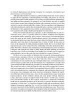
CONING
As the rotor blades turn, centrifugal force is created which pulls the blades outward from the
hub. When lift (or aerodynamic force) is created and combines with centrifugal force coning
occurs (see figure 3-11). Coning increases as lift increases.
Figure 3-11
VORTICES
As the rotor blades rotate and lift is produced, high pressure is formed below the blade and low
pressure above the blade. The sharp trailing edge of the blade keeps the high-pressure air from the
low-pressure area on most of the blade, except for the tip, where nothing prevents the air from
curling up from the bottom of the blade to the top. This air continues to spiral and drops off to
form the trailing tip vortex. This vortex continues to spin, and the velocity drops off with
increasing distance from the origin. In a hover, the vortices of one revolution impinge on the
vortices of the following revolutions, causing an uneven path of the vortices, which eventually
destroy each other. These tip vortices affect the induced velocity through the rotor system, and
due to this impingement and resultant unsteadiness in the flow field, a rotor system in a hover
creates its own gusty air, requiring the pilot to constantly correct to maintain a hover (figure 3-12).
Figure 3-12
CHAPTER 3 HELICOPTER AERODYNAMICS WORKBOOK
3-12 HELICOPTER POWERED FLIGHT ANALYSIS
To balance the tip vortices, another vortex is formed at the blade root which writhes around
erratically through and around the main rotor system. This root vortex has an equal and opposite
effect on the tip vortex, which the pilot must correct. This usually manifests itself in heading
changes as the root vortex impinges on the tail rotor and generally occurs when within one rotor
diameter of the ground. Main rotor vortices can also affect the tail rotor during specific wind
conditions which are covered in the TH-57 NATOPS Manual.
GROUND EFFECT
While the helicopter is in a hover and in other flight conditions close to the ground, it
encounters ground effect (figure 3-13), a favorable aerodynamic phenomenon which requires
less power. Less power is required because there is less induced drag to overcome while “in
ground effect.”
Figure 3-13
Since all of the induced velocities are reduced in ground effect and the velocity of air which
flows through the rotor system and reaches the ground goes to zero, induced drag is reduced and
less engine power is required (figure 3-14). As the helicopter moves vertically from the ground
to a distance out of ground effect (approximately one rotor diameter), the blades “see” a greater
induced velocity because the flow of air in the wake below the rotors is unimpeded. Combined
with rotational velocity, the resultant velocity is pointed slightly more downward, tilting the lift
vector aft, increasing the induced drag and power required to hover. The power savings can
amount to as much as 20%.
HELICOPTER AERODYNAMICS WORKBOOK CHAPTER 3
HELICOPTER POWERED FLIGHT ANALYSIS 3-13
Figure 3-14
GROUND VORTEX
During transition to forward flight the pilot will encounter several phenomena exclusive to
helicopter flight which, although encountered almost simultaneously, are discussed separately in
the following sections. The first is ground vortex.
As the helicopter accelerates from a hover in ground effect to forward flight, benefits of
ground effect can be lost at an altitude of less than ½ rotor diameter and airspeed between 5 and
20 knots. This is called ground vortex. As the helicopter moves forward, the rotor downwash
mixes with increased relative wind to create a rotating vortex, which eventually causes an
increased downwash through the rotor system. This simulates a climbing situation, increasing
power required. Eventually this vortex is overrun at a higher speed. These flow patterns are
better described in figure 3-15.
CHAPTER 3 HELICOPTER AERODYNAMICS WORKBOOK
3-14 HELICOPTER POWERED FLIGHT ANALYSIS
Figure 3-15
TRANSLATIONAL LIFT
About the same time ground vortex is overrun, the helicopter encounters another beneficial
aerodynamic effect called translational lift. This phenomenon occurs due to a decrease in
induced velocity. How is induced velocity reduced? Recall that during a hover we have a nearly
vertical mass airflow through the rotor disk and the continuous recirculation of our own wingtip
vortices, both of which contribute to a high induced flow (see figure 3-16). When transitioning
to forward flight the rotor outruns this continuous recirculation of old wingtip vortices and
begins to work in relatively undisturbed air. Moreover, the mass airflow through the rotors
becomes more horizontal as airspeed increases (see figure 3-17). Both effects combine to cause
a sharp decrease in induced flow, induced drag and, therefore, power required. Depending on
wind conditions, the onset of translational lift and ground vortex may or may not be noticed or
encountered during transition to forward flight.
HELICOPTER AERODYNAMICS WORKBOOK CHAPTER 3
HELICOPTER POWERED FLIGHT ANALYSIS 3-15
Figure 3-16
Figure 3-17
CHAPTER 3 HELICOPTER AERODYNAMICS WORKBOOK
3-16 HELICOPTER POWERED FLIGHT ANALYSIS
DISSYMMETRY OF LIFT
To begin this discussion, we need to backtrack all the way to rotor system control. In a no-
wind hover, the rotational velocity each blade sees throughout each revolution is equal. In
forward flight, the velocity distribution varies (figure 3-18). The advancing side of the rotor disc
sees a combination of rotor speed and forward airspeed (movement through the air mass) which
is faster than the retreating side, which sees a combination of rotor speed and a "reduced"
forward airspeed. For a given pitch setting, and AOA, an equal amount of lift will be produced
throughout the rotor disc in a no-wind hover, but in forward flight, the advancing side will
generate more lift, thus developing a rolling moment. The ingenious method of equalizing this
dissymmetry of lift in forward flight is to allow the blades to flap. By connecting the blades to
the hub by a method which allows a flexible up-down motion, the advancing blade, which
encounters higher lift, begins to flap upward. The retreating blade, which encounters less lift,
flaps downward. Flapping equilibrium is found at a point where the rotor system has an AOA
which compensates for changes in airspeed throughout the rotor disk revolution.
Figure 3-18
HELICOPTER AERODYNAMICS WORKBOOK CHAPTER 3
HELICOPTER POWERED FLIGHT ANALYSIS 3-17
PHASE LAG
The advancing blade will encounter its highest rotational speed 90° prior to a position over
the nose of the aircraft, but does not experience the highest degree of flapping at this point
(figure 3-19). In fact, this maximum flapping occurs over the nose, 90° later, due to a principle
of a dynamic system in resonance. A system in resonance receives a periodic excitation force
sympathetic with the natural frequency of the system. The flapping frequency of a centrally
hinged system is equal to the speed of rotation. Therefore, maximum response occurs 90° after
maximum periodic excitation. This is termed phase lag. In order for a helicopter in forward
flight to roll into a left turn, maximum lift must be realized at the right "wing" position and
minimum lift must be realized at the left "wing" position. Therefore, maximum AOA must
occur at the 180° position and minimum AOA must occur at the 360° position. To obtain the
appropriate response 90° after maximum excitation, logic tells us forward cyclic is the
appropriate input to initiate a left turn. No wonder helicopters are such a challenge to fly! Well,
they are challenging, but not for this reason. Inputs are translated 90° prior mechanically, thanks
to some design engineers who had a little foresight.
Figure 3-19
BLOWBACK
Let's get back to dissymmetry of lift. As the aircraft moves forward, the advancing blade
"sees" a higher airspeed, and the resultant dissymmetry of lift causes the blades to flap to a
maximum 90° later due to phase lag. This extra lift generated over the nose causes the nose to
pitch up. Conversely, the nose will tend to pitch down as the aircraft decelerates. The combined
effect of dissymmetry of lift and reduced induced velocity defines this transition to a more efficient
flight regime, called translational lift. The pitch-up tendency of the aircraft as it accelerates and
the pitch-down tendency as it decelerates are known as rotor blowback (figure 3-20).
CHAPTER 3 HELICOPTER AERODYNAMICS WORKBOOK
3-18 HELICOPTER POWERED FLIGHT ANALYSIS
Figure 3-20
Forward cyclic input in proportion to degree of blowback must be used to maintain a
constant rate of acceleration. Aft cyclic will be required during deceleration.
As the helicopter transitions to a hover from a decelerating glide slope as in a normal
approach, it often experiences an uncommanded nose-up tendency not nose-down as described
above. This is referred to as Pendulum Effect, and it occurs in response to increased collective
pitch. Although collective blade pitch is increased proportionally, forward flight dissymmetry of
lift is augmented. This overrides the effects of decelerating rotor blowback and causes the nose
of the aircraft to pitch up (figure 3-20).
TRANSVERSE FLOW AND CONING
Another phenomenon which occurs at about 15-20 kts is a non-uniform induced velocity
flow pattern across the rotor, or transverse flow. The wake vortices behind the rotor create
nearly twice the induced velocity at the trailing edge of the rotor disk as compared to the leading
edge, where it is approximately zero (figure 3-21).
Figure 3-21
This causes the blade over the nose to see an increase in AOA and, coupled with phase lag,
makes the rotor flap up on the left side. A sudden left cyclic input during acceleration may be
necessary to counteract this flapping. This fore-and-aft asymmetry of lift continues in forward
flight due to coning (figure 3-22), a steady upward flapping due to blade lift and centrifugal
force. In slow forward flight, coning causes the component of inflow to be more "up" in the
blade over the nose in comparison to the component of inflow over the tail.
HELICOPTER AERODYNAMICS WORKBOOK CHAPTER 3
HELICOPTER POWERED FLIGHT ANALYSIS 3-19
Figure 3-22
Therefore, the lift on the retreating blade is low because the rotational speed it “sees” is low.
The lift on the advancing blade is low because it must not overbalance the lift on the retreating
side. The blades over the nose and tail have the primary responsibility of producing the lift
necessary to keep the helicopter airborne in forward flight.
CHAPTER 3 HELICOPTER AERODYNAMICS WORKBOOK
3-20 HELICOPTER POWERED FLIGHT ANALYSIS
CHAPTER THREE REVIEW QUESTIONS
1. To make a hovering turn to the left in no-wind conditions, one must increase/decrease tail
rotor thrust.
2. How does a multi-rotor headed helicopter account for torque effect? ___________________
______________________________
3. Power required by the tail rotor to maintain heading while increasing collective setting will
increase/decrease, therefore increasing/decreasing power available to the main rotor system.
4. The ___________________________ effect and ___________________________ provide
anti torque compensation in forward flight.
5. How does tail rotor thrust affect vertical takeoffs and landings?_______________________.
6. The apparent axis of rotation of the main rotor system is called the____________________.
7. The actual axis of rotation is called the_________________________________.
8. The center of mass of the entire aircraft is called the________________________________.
9. When the virtual axis is displaced, the ____________________________ will attempt to
align itself with it, causing ___________________________.
10. Why is cyclic authority lost when center of gravity is out of limits?____________________
__________________________
11. The phenomenon requiring control inputs 90 degrees ahead of the location of desired result.
________________________________________________________________________
12. When a helicopter enters forward flight, the advancing blade generates more lift than the
retreating blade, causing __________________________________________________.
13. ___________________________causes the nose to pitch up/down because of blade flapping
over the nose caused by the combined effects of________________ and ____________.
14. Translational lift is caused by an increase of _______________________ introduced to the
rotor system and a decrease of _________________________.
15. Ground effect is caused by a reduction of_________________________ due to helicopter
operations within________ rotor diameter of the ground.
16. The resultant upward displacement of the rotor blades due to___________________ and
______________________is called coning.