A Guide to BS EN 62305:2006 Protection Against Lightning Part 5 pps
Bạn đang xem bản rút gọn của tài liệu. Xem và tải ngay bản đầy đủ của tài liệu tại đây (1.51 MB, 13 trang )
51
www.furse.com
Tall structures
As modern construction techniques improve, the
height of structures is increasing. Super structures
approaching almost 1km in height are now being
constructed. This standard devotes a small section to
this topic but recognizes further more specific
recommendations will be required in future editions.
One of the major protection measures required is to
ensure adequate protection is afforded to the upper
sides of these super structures to minimise any
protection damage from side flashes to the structure.
Research shows that it is the upper 20% of the
structure that is most vulnerable to side strikes and
potential damage.
Tall structures | BS EN 62305-3
Figure 4.23: Petronas Towers, Malaysia
Equipotential bonding is another important aspect
and with these particular structures it is vital to utilize
the vast fortuitous metalwork present both in the
concrete encased steel as well as the metallic cladding
adorning it.
Natural components
When metallic roofs are being considered as a natural
air termination arrangement, then BS 6651 gives
guidance on the minimum thickness and type of
material under consideration. BS EN 62305-3 gives
similar guidance as well as additional information if
the roof has to be considered puncture proof from a
lightning discharge. Table 4.5 refers.
Class of LPS Material
Thickness
(1)
t (mm)
Thickness
(2)
t’ (mm)
I to IV
Lead - 2.0
Steel (stainless,
galvanized)
4 0.5
Copper 5 0.5
Aluminium 7 0.65
Zinc - 0.7
Table 4.5: Minimum thickness of metal sheets or metal pipes
in air termination systems (BS EN 62305-3 Table 3)
(1) Thickness t prevents puncture, hot spot or ignition.
(2) Thickness t’ only for metal sheets if it is not important to prevent
puncture, hot spot or ignition problems.
We believe this table has an error included. The
dimension for tape and stranded conductors fixed to
horizontal surfaces should be 1,000mm and not the
stated 500mm.
Although this was pointed out to the Technical
Committee Working Group, it was too late, as the
IEC/CENELEC Standard had already been published.
Therefore the error will have to wait until the next
technical review, which is due to take place in 2010.
BS EN 62305 will then be amended accordingly.
Numerous illustrations are given in Annex E of the
positioning and relevant use of natural conductors
(fortuitous metalwork) as down conductors and lateral
conductors and equipotential bonding, all elements
contributing to a more effective LPS.
Sometimes it is not possible to install down conductors
down a particular side of a building due to practical or
architectural constraints. On these occasions more
down conductors at closer spacings on those sides that
are accessible should be installed as a compensating
factor.
The centres between these down conductors should
not be less than one third of the distances given in
Table 4.6.
A test joint should be fitted on every down conductor
that connects with the earth termination. This is
usually on the vertical surface of the structure,
sufficiently high to minimise any unwanted third party
damage/interference. Alternatively, the test or
disconnection point can be within the inspection
chamber that houses the down conductor and earth
rod. The test joint should be capable of being opened,
removed for testing and reconnected. It shall meet the
requirements of BS EN 50164-1.
Similar to BS 6651, this standard permits the use of an
aesthetic covering of PVC or protective paint over the
external LP conductors. (See clause 4.2 of
BS EN 50164-2(A1)).
BS EN 62305-3 | Down conductors
52
www.furse.com
Down conductors
Down conductors should within the bounds of
practical constraints take the most direct route from
the air termination system to the earth termination
system. The lightning current is shared between the
down conductors. The greater the number of down
conductors, the lesser the current that flows down
each. This is enhanced further by equipotential
bonding to the conductive parts of the structure.
Lateral connections either by fortuitous metalwork or
external conductors made to the down conductors at
regular intervals (see Table 4.6) is also encouraged.
The down conductor spacing corresponds with the
relevant Class of LPS.
There should always be a minimum of two down
conductors distributed around the perimeter of the
structure. Down conductors should wherever possible
be installed at each exposed corner of the structure as
research has shown these to carry the major part of
the lightning current.
Down conductors should not be installed in gutters or
down spouts even if they are insulated due to the risk
of corrosion occurring.
Fixing centres for the air termination and down
conductors are shown in Table 4.7.
Class of LPS Typical distances (m)
I 10
II 10
III 15
IV 20
Table 4.6: Typical values of the distance between down
conductors and between ring conductors according to the
Class of LPS (BS EN 62305-3 Table 4)
Arrangement Tape and stranded
conductors
(mm)
Round solid
conductors
(mm)
Horizontal conductors
on horizontal surfaces
500 1,000
Horizontal conductors
on vertical surfaces
500 1,000
Vertical conductors from
the ground to 20 m
1,000 1,000
Vertical conductors from
20 m and thereafter
500 1,000
This table does not apply to built-in type fixings which may require special
considerations. Assessment of environmental conditions (ie expected wind
load) shall be undertaken and fixing centres different from those
recommended may be found to be necessary
Table 4.7: Suggested conductor fixing centres
(BS EN 62305-3 Table E.1)
BS EN 62305-3 Physical damage to
structures and life hazard
53
www.furse.com
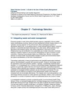
Structure with a cantilevered part
As with BS 6651, BS EN 62305-3 addresses the
potential problem associated with a person, standing
under the overhang of a cantilevered structure during
a thunderstorm. The problem is illustrated in
Figure 4.24.
Structure with a cantilevered part | BS EN 62305-3
To reduce the risk of the person becoming an
alternative path for the lightning current to that of
the external down conductors, then the following
condition should be satisfied:
Where:
h = Height of the overhang (in metres)
s = Required separation distance calculated
in accordance with Section 6.3 of
BS EN 62305-3
Figure 4.24: Cantilevered structure
Ground level
2.5m
External down
conductor
Structure
h
w
s
Where:
k
i
= 0.08 for LPS Class I (see Table 4.13 )
k
c
= 0.66 for 2 down conductors
(see Table 4.14 and Table 4.16 )
k
m
= 1 for air (see Table 4.15 )
l =
So for a height h, the maximum width w of the
overhang should be:
hs>+25.
(4.1)
sk
k
k
l=× ×
i
c
m
(4.2)
Height of overhang h
(m)
Width of overhang w
(m)
3 9.5
3.5 19
4.0 28.5
4.5 38
5 47.5
Table 4.8: Maximum allowable cantilever for LPL I
wh+
hk
k
k
wh−=××+
()
25.
i
c
m
hwh−= × ×+
()
25 008
1
0.66
hwh−= ×+
()
25 00528
wh=× ×−
()
18 94 0 9472 2 5 .
wh≈×−
()
19 2 5.
The above is based on 2 external, equally spaced down
conductors and a Type A earthing arrangement. If the
above conditions cannot be fulfilled, consideration
should be given to increasing the number of down
conductors, or alternatively, routeing the down
conductors internally. The requirement of the
separation distance would still need to be satisfied.
The separation distance s is covered in more detail on
page 65, Separation (isolation) distance of the external
LPS. For the purpose of determining h, the separation
distance can be determined by using Equation 4.2.
Although BS 6651 advocates the use of reinforcing for
equipotential bonding, BS EN 62305 emphasises on its
importance.
It encourages a meshed connection conductor
network (see E4.3.8 of BS EN 62305-3), even to the
extent of utilizing dedicated ring conductors installed
inside or outside the concrete on separate floors of
the structure at intervals not greater than 10m.
Foundation earth termination systems usually found
in large structures and industrial plants are also
encouraged.
BS EN 62305-3 | Natural components
54
www.furse.com
Natural components
The philosophy of the design, like BS 6651, encourages
the use of fortuitous metal parts on or within the
structure, to be incorporated into the LPS.
Where BS 6651 requires electrical continuity when
using reinforcing bars located in concrete structures,
so too does BS EN 62305-3. Additionally, it states that
the vertical reinforcing bars are welded, or clamped
with suitable connection components or overlapped a
minimum of 20 times the rebar diameter. This is to
ensure that those reinforcing bars likely to carry
lightning currents have secure connections from one
length to the next.
If the reinforcing bars are connected for equipotential
bonding or EMC purposes then wire lashing is deemed
to be suitable.
Additionally, the reinforcing bars – both horizontal
and vertical – in many new structures will be so
numerous that they serve as an electromagnetic shield
which goes some way in protecting the electrical and
electronic equipment from interference caused by
lightning electromagnetic fields.
When internal reinforcing bars are required to be
connected to external down conductors or earthing
network either of the arrangements shown in
Figure 4.25 is suitable. If the connection from the
bonding conductor to the rebar is to be encased in
concrete then the standard recommends that two
clamps are used, one connected to one length of
rebar and the other to a different length of rebar.
The joints should then be encased by a moisture
inhibiting compound such as Denso tape.
If the reinforcing bars (or structural steel frames)
are to be used as down conductors then electrical
continuity should be ascertained from the air
termination system to the earthing system. For new
build structures this can be decided at the early
construction stage by using dedicated reinforcing bars
or alternatively to run a dedicated copper conductor
from the top of the structure to the foundation prior
to the pouring of the concrete. This dedicated copper
conductor should be bonded to the adjoining/adjacent
reinforcing bars periodically.
If there is doubt as to the route and continuity of the
reinforcing bars within existing structures then an
external down conductor system should be installed.
These should ideally be bonded into the reinforcing
network at the top and bottom of the structure.
BS EN 62305-3 gives further guidance regarding the
electrical continuity of steel reinforced concrete by
stating a maximum overall electrical resistance of
0.2 ohm. This should be achieved when measuring the
electrical continuity from the top of the structure
down to its foundations. On many occasions this is not
practical to carry out. The standard then advocates
that an external down conductor system be employed.
Figure 4.25: Typical methods of bonding to steel
reinforcement within concrete
Stranded copper cable
(70mm
2
PVC insulated)
Cast in
non-ferrous
bonding
point
Bonding conductor
Clamped cable to rebar
connection
Steel reinforcement within
concrete (rebar)
BS EN 62305-3 Physical damage to
structures and life hazard
55
www.furse.com
Type A arrangement
This consists of horizontal or vertical earth electrodes,
connected to each down conductor fixed on the
outside of the structure. This is in essence, the
earthing system used in BS 6651 where each down
conductor has an earth electrode (rod) connected to
it.
The total number of earth electrodes shall not be less
than two. The minimum length for a horizontal or
vertical electrode is determined from Figure 4.26
(Figure 2 of BS EN 62305-3).
In the case of vertical electrodes (rods) when used in
soils of resistivity 500 ohms metres or less, then the
minimum length of each rod shall be 2.5m. However,
the standard states that this minimum length can be
disregarded provided that the earth resistance of the
overall earth termination system is less than 10 ohms.
Conversely, if the 10 ohm overall value cannot be
achieved with 2.5m long earth rods, it will be
necessary to increase the length of the earth rods or
combine them with a Type B ring earth electrode until
a 10 ohm overall value is achieved.
It further states that the earth electrodes (rods) shall
be installed such that the top of each earth rod is at
least 0.5m below finished ground level. The electrodes
(rods) should be distributed around the structure as
uniformly as possible to minimise any electrical
coupling effects in the earth.
Earth termination system | BS EN 62305-3
Earth termination system
The earth termination system is vital for the dispersion
of the lightning current safely and effectively into the
ground. Although lightning current discharges are a
high frequency event, at present most measurements
taken of the earthing system are carried out using low
frequency proprietary instruments. The standard
advocates a low earthing resistance requirement and
points out that can be achieved with an overall earth
termination system of 10 ohms or less.
In line with BS 6651, the standard recommends a
single integrated earth termination system for a
structure, combining lightning protection, power and
telecommunication systems. The agreement of the
operating authority or owner of the relevant systems
should be obtained prior to any bonding taking place.
Three basic earth electrode arrangements are used.
● Type A arrangement
● Type B arrangement
● Foundation earth electrodes
Figure 4.26: Minimum length of earth electrode
0
0
Note 3
500 1,500 1,000
LPS Class III - IV
LPS Class II
LPS Class I
2,000 2,500 3,000
10
20
30
40
50
60
70
80
90
100
Note 2 Note 1
l
1
(m)
C
C
C
BS EN 62305-3 | Earth termination system
56
www.furse.com
From a practical point of view this means that the
top 0.5m from ground level down would need to be
excavated prior to commencing the installation of the
earth rod.
Another way of fulfilling this earthing requirement
would be to drive the required extensible earth rods
from ground level and complete the installation by
driving an insulated section of earth rod that was
connected to these earth rods and was terminated at
ground level.
The following table gives an indication of how many
earth rods would be required to achieve 10 ohms or
less for varying soil resistivities.
As the most popular size of earth rod used in many
countries is 1.2m (4ft) or multiples thereof, the values
are based on a 2.4m (2 x 4ft) length of earth rod
electrode.
Type B arrangement
This arrangement is essentially a ring earth electrode
that is sited around the periphery of the structure and
is in contact with the surrounding soil for a minimum
80% of its total length (ie 20% of its overall length
may be housed in say the basement of the structure
and not in direct contact with the earth).
The minimum length of the ring earth electrode is also
determined from Figure 4.26 (Figure 2 of
BS EN 62305-3). For soil of resistivity 500 ohm metres
or less, the minimum length of electrode shall be 5m.
The mean radius of the area enclosed by the ring
earth electrode is also taken into account to
determine whether additional horizontal or vertical
electrodes are required. In reality provided the
structure is not smaller than 9m x 9m and the soil
resistivity is less than 500 ohm metres then the ring
electrode will not need to be augmented with
additional electrodes. The medium/large size
structures will automatically have a ring electrode
greater in length than 5m.
The ring electrode should preferably be buried at a
minimum depth of 0.5m and about 1m away from the
external walls of the structure.
Where bare solid rock conditions are encountered, the
type B earthing arrangement should be used.
The Type B ring earth electrode is highly suitable for:
● Conducting the lightning current safely to earth
● Providing a means of equipotential bonding
between the down conductors at ground level
● Controlling the potential in the vicinity of
conductive building wall
● Structures housing extensive electronic systems
or with a high risk of fire
Foundation earth electrodes
This is essentially a type B earthing arrangement. It
comprises conductors that are installed in the concrete
foundation of the structure. If any additional lengths
of electrodes are required they need to meet the same
criteria as those for Type B arrangement. Foundation
earth electrodes can be used to augment the steel
reinforcing foundation mesh. Earth electrodes in soil
should be copper or stainless steel when they are
connected to reinforcing steel embedded in concrete,
to minimise any potential electrochemical corrosion.
Table 4.9: Earth rods required to achieve 10 ohms
Resistivity
(ohm m)
Number of
earth rods
Length of earth rod
(m)
500 50 2.4
400 38 2.4
300 28 2.4
200 18 2.4
100 8 2.4
50 3 2.4
Potential corrosion, soil drying out, or freezing is also
considered with regard to achieving a stabilised earth
resistance value of the earth rod. In countries where
extreme weather conditions are found, for every
vertical electrode (rod) the standard recommends that
0.5m should be added to each length, to compensate
for the detrimental effect from some of the extreme
seasonal soil conditions that are likely to be
encountered.
BS EN 62305-3 Physical damage to
structures and life hazard
57
www.furse.com
Earthing – General
A good earth connection should possess the following
characteristics:
● Low electrical resistance between the electrode
and the earth. The lower the earth electrode
resistance the more likely the lightning current
will choose to flow down that path in preference
to any other, allowing the current to be conducted
safely to and dissipated in the earth.
● Good corrosion resistance. The choice of material
for the earth electrode and its connections is of
vital importance. It will be buried in soil for many
years so has to be totally dependable.
Soil Conditions
Achieving a good earth will depend on local soil
conditions. A low soil resistivity is the main aim and
factors that effect this are:
● Moisture content of the soil
● Chemical composition of the soil, eg salt content
● Temperature of the soil
The following tables illustrate the effect these factors
have on the soil resistivity.
Although Table 4.11 quotes figures for salt laden soil,
it is now deemed bad practice to use salt as a chemical
means of reducing soil resistivity, because of its very
corrosive nature. Salt along with other chemicals, has
the disadvantage of leaching out of the surrounding
soil after a period of time, thus returning the soil to its
original resistivity.
Earthing – General | BS EN 62305-3
Table 4.10: Effect of moisture on resistivity
Moisture content
% by weight
Resistivity (Ωm)
Top soil Sandy loam
0
10 x 10
6
10 x 10
6
2.5 2,500 1,500
5 1,650 430
10 530 185
15 310 105
20 120 63
30 64 42
Added salt
(% by weight of moisture)
Resistivity
(Ωm)
0 107
0.1 18
1 4.6
5 1.9
10 1.3
20 1.0
It should be noted that, if the soil temperature
decreases from +200°C to –50°C, the resistivity
increases more than ten times.
Resistance to earth
Once the soil resistivity has been determined and an
appropriate type earth electrode system chosen, its
resistance to earth can be predicted by using the
typical formulae listed below:
For horizontal strip electrode (circular or rectangular
section)
or for vertical rods
Where:
R = Resistance in ohms
ρ
= Soil resistivity in ohm metres (Ωm)
L = Length of electrode in metres
w = Width of strip or diameter of circular
electrode in metres
d = Diameter of rod electrode in metres
h = Depth of electrode in metres
Q = Coefficients for different arrangements
-1 for rectangular section,
-1.3 for circular section
Temperature
Resistivity
(Ωm)
°C °F
20 68 72
10 50 99
0 32 (water) 138
0 32 (ice) 300
–5 23 790
–15 14 3,300
R
L
L
wh
Q
e
=
⎛
⎝
⎜
⎞
⎠
⎟
+
⎡
⎣
⎢
⎢
⎤
⎦
⎥
⎥
ρ
π
2
2
2
log
(4.3)
R
L
L
d
e
=
⎛
⎝
⎜
⎞
⎠
⎟
−
⎡
⎣
⎢
⎤
⎦
⎥
ρ
π
2
8
1log
(4.4)
Table 4.12: Effect of temperature on resistivity
(based on sandy loam, 15.2% moisture)
Table 4.11: Effect of salt on resistivity
(based on sandy loam, 15.2% moisture)
Lightning Protection Components
(LPC)
The correct choice of material, configuration and
dimensions of the lightning protection components is
essential when linking the various elements of an LPS
together. The designer/user needs to know that the
components, conductors, earth electrodes etc will
meet the highest levels when it comes to durability,
long term exposure to the environmental elements
and perhaps most importantly of all, the ability to
dissipate the lightning current safely and harmlessly to
earth. The BS EN 50164 series have been compiled
with this very much in mind. At present three
standards are published within the BS EN 50164 series.
These are:
● BS EN 50164-1:2000 Lightning protection
components (LPC) Part 1:Requirement for
connection components
● BS EN 50164-2:2002 Lightning protection
components (LPC) Part 2: Requirements for
conductors and earth electrodes
● BS EN 50164-3:2006 Lightning protection
components (LPC) Part 3: Requirements for
isolating spark gaps (ISG)
There are currently several other parts of BS EN 50164
under compilation by the relevant working group in
CENELEC.
These are:
● BS EN 50164-4 Lightning protection components
(LPC) Part 4: Requirements for conductor fasteners
● BS EN 50164-5 Lightning protection components
(LPC) Part 5: Requirements for earth electrode
inspection housings and earth electrode seals
● BS EN 50164-6 Lightning protection components
(LPC) Part 6: Requirements for lightning strike
counters
● BS EN 50164-7 Lightning protection components
(LPC) Part 7: Requirements for earth enhancing
compounds
All of these are in draft format and only when they
are mature enough for voting by the National
Committees will it be decided whether they will be
approved and ultimately published.
BS EN 62305-3 | Earth electrode testing
58
www.furse.com
Earth electrode testing
BS 6651 is quite clear in its methodology statement
relating to the testing of the lightning protection
earthing system surrounding a building.
Unfortunately, in BS EN 62305-3 clause E.7.2.4, we
believe this to be somewhat vague in its intent.
Our interpretation of this clause when applied to
Type A arrangement is that with the test link removed
and without any bonding to other services etc, the
earth resistance of each individual earth electrode
should be measured.
With the test links replaced the resistance to earth of
the complete lightning protection is measured at any
point on the system. The reading from this test should
not exceed 10 ohms. This is still without any bonding
to other services.
If the overall earth reading is greater than 10 ohms
then the length of the earth rod electrode should be
increased by the addition of further sections to the
extensible earth rod. (Typically, add another section of
earth rod to increase its length from 2.4m to 3.6m).
Similar to BS 6651, there is a statement to the effect
that if the building is located on rocky soil then the
10 ohm requirement is not applicable.
BS EN 62305-3 Physical damage to
structures and life hazard
BS EN 50164-1 is a performance specification.
It attempts to simulate actual installation conditions.
The connection components are configured and tested
to create the most onerous application. A pre-
conditioning or environmental exposure initially takes
place (see Figure 4.27 and Figure 4.28) followed by
three 100kA electrical impulses, which simulate the
lightning discharge (see Figure 4.29). A pre- and
post-measuring/installation torque is applied to each
component as part of the test regime along with
initial and post resistance measurements either side
of the electrical impulses.
59
www.furse.com
Lightning Protection Components | BS EN 62305-3
Figure 4.27: Environmental ageing chamber for salt mist and
humid sulphurous atmosphere ageing
Figure 4.28: Environmental ageing chamber for ammonia
atmosphere ageing
Figure 4.29: 100kA impulse current generator
BS EN 62305-3 | Earth electrode testing
60
www.furse.com
BS EN 62305-3 Physical damage to
structures and life hazard
Figure 4.31: Air terminal base (Part no SD105)
Figure 4.32: Oblong test clamp (Part no CN105)
Figure 4.33: Square tape clamp (Part no CT005)
Figure 4.34: Square tape clamp (Part no CT105)
For connection components used above ground, the
specimens are subject to a salt mist treatment for
three days, followed by exposure to a humid,
sulphurous atmosphere for seven days. For specimens
made of copper alloy with a copper content of less
than 80%, a further one day of ammonia atmosphere
treatment is added. For components that are buried
in the ground, the specimens are immersed in an
aqueous solution containing chloride (CaCl
2
) and
sulphate (NA
2
SO
4
) for 28 days. A range of
pre-conditioned Furse components alongside an
off-the-shelf original are shown in Figures 4.31 to 4.37.
Figure 4.30: Arrangement of specimen for a typical
cross-connection component
500mm
500mm
20mm
20mm
Insulating plate
Conductor fixing
Conductor
Connection component
Electrical connections
The tests are carried out on three specimens of the
components. The conductors and specimens are
prepared and assembled in accordance with the
manufacturer’s instructions, eg recommended
tightening torques. A typical test arrangement is
illustrated in Figure 4.30.
61
www.furse.com
The electrical impulse test was particularly onerous.
The following photographs show a Furse connection
component before and after the electrical impulses.
Poorly designed components would have been thrown
from the conductors by the enormous electromagnetic
forces created.
Lightning Protection Components | BS EN 62305-3
Figure 4.35: Type ‘B’ bond (Part no BN005)
Figure 4.36: Type ‘B’ bond (Part no BN105)
Figure 4.37: Square clamp (Part no CS610)
Figure 4.38: Effects of the electrical impulse test
All Furse connection components have successfully
completed the BS EN 50164-1 testing at a purpose
built laboratory and have been witnessed by an
internationally recognised inspection organisation
– Bureau Veritas. Test resports are available for all the
connection components tested.
BS EN 62305-3 | Lightning Protection Components
62
www.furse.com
Lightning equipotential bonding
Equipotential bonding is simply the electrical
interconnection of all appropriate metallic
installations/parts, such that in the event of lightning
currents flowing, no metallic part is at a different
voltage potential with respect to another. If the
metallic parts are essentially at the same potential
then the risk of sparking or flash over is nullified.
This electrical interconnection can be achieved by
natural/fortuitous bonding or by using specific
bonding conductors that are sized according to
Tables 8 and 9 of BS EN 62305-3.
Bonding can also be accomplished by the use of surge
protection devices (SPDs) where the direct connection
with bonding conductors is not suitable. SPDs must be
installed in such a way that they are readily accessible
and visible for inspection purposes
Prior to carrying out any lightning equipotential
bonding that involves telecom networks and power
utility cables, permission should be obtained from the
operator of these systems to ensure there are no
conflicting requirements.
For structures taller than 30m the standard
recommends that equipotential bonding is carried out
at basement/ground level and then every 20m
thereafter. A sufficient electrical insulation or
‘separation’ distance should always be maintained
between the appropriate metallic installations/parts.
Wherever protection of internal systems against
overvoltages caused by a lightning discharge requires
SPDs, these shall conform to BS EN 62305-4. This topic
is covered in greater detail in Section 5 of this guide.
Figure 4.40 (based on BS EN 62305-3 fig E.45) shows
a typical example of an equipotential bonding
arrangement. The gas, water and central heating
system are all bonded directly to the equipotential
bonding bar located inside but close to an outer wall
near ground level. The power cable is bonded via a
suitable SPD, downsream from the electric meter, to
the equipotential bonding bar. This bonding bar
should be located close to the main distribution board
(MDB) and also closely connected to the earth
termination system with short length conductors. In
larger or extended structures several bonding bars
may be required but they should all be interconnected
with each other.
The screen of any antenna cable along with any
shielded power supply to electronic appliances being
routed into the structure should also be bonded at the
equipotential bar. Further guidance relating to
equipotential bonding, meshed interconnection
earthing systems and SPD selection is given in
BS EN 62305-4 and the relevant section of this guide.
BS EN 62305-3 Physical damage to
structures and life hazard
BS EN 50164-2 is both a design and in parts a
performance specification. It lists down the conductor
and earth electrode types suitable for lightning
protection applications. Tables 6 and 7 of
BS EN 62305-3 are essentially copied from
BS EN 50164-2 with minor modifications. Additionally,
Tables 2 and 4 from BS EN 50164-2 give information
relating to the mechanical and electrical requirements
of the conductors and earth electrodes. Also included
are tensile, adhesion, bend and environmental test
criteria. All applicable Furse conductors and earth
electrodes meet the requirements of BS EN 50164-2.
BS EN 50164-3 covers the application of spark gaps
when used in an LPS. A typical application would be
when certain metal installations need to be isolated
from the nearby external down conductors to prevent
any potential corrosion cells being created. A spark
gap would bridge across both components and in the
event of a lightning current discharge would then
conduct and link both components electrically.
BS EN 62305-3 devotes several pages to the correct use
of components and stipulates compliance to the
BS EN 50164 series.
By choosing lightning connection components
complying with the BS EN 50164 series the designer is
certain that he is using the best products on the
market and is in compliance with the BS EN 62305
series.
Internal LPS design considerations
The fundamental role of the internal LPS is to ensure
the avoidance of dangerous sparking occurring within
the structure to be protected. This could be due,
following a lightning discharge, to lightning current
flowing in the external LPS or indeed other conductive
parts of the structure and attempting to flash or spark
over to internal metallic installations.
Carrying out appropriate equipotential bonding
measures or ensuring there is a sufficient electrical
insulation distance between the metallic parts can
avoid dangerous sparking between different metallic
parts.
63
www.furse.com
Lightning equipotential bonding | BS EN 62305-3
Lightning equipotential bonding for external LPS
In the case of equipotential bonding of an external
LPS the installation should be carried out in the
basement or at ground level of the structure. The
bonding conductor should have a direct connection
to an earth bonding bar which in turn should be
connected to the earth termination system.
If gas or water pipes entering the structure have
insulated inserts incorporated into them, then these
insulated sections should be bridged by suitably
designed SPDs. Agreement with the relevant utility
should be sought prior to installation.
Lightning equipotential bonding for external
conductive parts should be carried out as near to the
point of entry into the structure as possible. If direct
bonding is not acceptable then suitably designed SPDs
should be used.
When and if the risk assessment calculation indicates
that a Lightning Protection System (LPS) is not
required, but that equipotential bonding SPDs are,
then the earth termination system of the low voltage
electrical installation can be utilised.
Figure 4.40: Example of main equipotential bonding
Equipotential
bonding bar
Central heating system
Screen of antenna cable
Electronic appliances
Power from utility
Meter
Meter
Gas
Water
Electricity
meter
Consumer unit/
fuseboard
SPD
ON
OFF
Neutral bar
Live bar
Lightning equipotential bonding for internal
systems
If the conductors within the structure have an outer
screening or are installed within metal conduits then
it may be sufficient to only bond these screens and
conduits.
However, this may not avoid failure of equipment
due to overvoltages. In this case coordinated SPDs
designed and installed in accordance with
BS EN 62305-4 should be used.
If these internal conductors are neither screened or
located in metal conduits, they should be bonded
using suitably designed SPDs.
Equipotential bonding of external services
Ideally, all metallic services along with the power, data
and telecom supplies should enter the structure near
ground level at one common location. Equipotential
bonding should be carried out as close as possible to
the entry point into the structure.
If the cables (power, telecom etc) entering the
structure are of a shielded construction, then these
shields should be connected directly to the
equipotential bonding bar. The other ‘live’ cores
should be bonded via suitable SPDs.