Desiccant Enhanced Evaporative Air-Conditioning phần 2 docx
Bạn đang xem bản rút gọn của tài liệu. Xem và tải ngay bản đầy đủ của tài liệu tại đây (5.14 MB, 10 trang )
1.0 Introduction
1.1 Intention
Our intent is to describe the desiccant enhanced evaporative air conditioner (DEVap A/C)
concept. To do this, we must give background in A/C design and liquid desiccant technology.
After which, we can describe the concept which consists of a novel A/C geometry and a resulting
process. We do this by:
• Discussing the goals of an air conditioner in comparison to expectations
• Discussing the benefits of combining desiccant technology and indirect evaporative
cooling
• Describing the DEVap A/C process
• Providing a physical description of the DEVap device
• Discussing the energy savings potential
• Assessing the risks of introducing this novel concept to the marketplace
• Discussing future work to bring this concept to the marketplace.
This information is intended for an audience with technical knowledge of heating, ventilating,
and air-conditioning (HVAC) technologies and analysis.
1.2 Background
Today’s A/C is primarily based on the direct expansion (DX) or refrigeration process, which was
invented by Willis Carrier more than 100 years ago. It is now so prevalent and entrenched in
many societies that it is considered a necessity for maintaining efficient working and living
environments. DX A/C has also had more than 100 years to be optimized for cost and
thermodynamic efficiency, both of which are nearing their practical limits. However, the
positive impact of improved comfort and productivity does not come without consequences.
Each year, A/C uses approximately 4 out of 41 quadrillion Btu (quads) of the source energy used
for electricity production in the United States alone, which results in the release of about 380
MMT of carbon dioxide into the atmosphere (DOE 2009).
R-22 (also known as Freon) as a refrigerant for A/C is quickly being phased out because of its
deleterious effects on the ozone layer. The most common remaining refrigerants used today (R-
410A and R-134A) are strong contributors to global warming. Their global warming potentials
are 2000 and 1300, respectively (ASHRAE 2006). Finding data on air conditioner release rates
is nearly impossible, as they are generally serviced only when broken and refrigerant recharge is
not accurately accounted for. A typical residential size A/C unit may have as much as 13 pounds
of R-410A, and a 10-ton commercial A/C has as much as 22 pounds.
Water is not commonly considered to be a refrigerant, but the American Society of Heating,
Refrigerating and Air-Conditioning Engineers (ASHRAE 2009) recognizes it as the refrigerant
R-718. Evaporative cooling uses the refrigerant properties of water to remove heat the same way
DX systems use the refrigeration cycle. Water evaporates and drives heat from a first heat
reservoir, and then the vapor is condensed into a second reservoir. Evaporative cooling is so
efficient because atmospheric processes in nature, rather than a compressor and condenser heat
exchanger, perform the energy-intensive process of recondensing the refrigerant. Water is
delivered to the building as a liquid via the domestic water supply.
1
NREL’s thermally activated technology program has been developing, primarily with AIL
Research (AILR) as our industry partner, liquid-desiccant-based A/C (LDAC) for more than 15
years. The technology uses liquid desiccants to enable water as the refrigerant in lieu of
chlorofluorocarbon-based refrigerants to drive the cooling process. The desiccants are strong
salt water solutions. In high concentrations, desiccants can absorb water from air and drive
dehumidification processes; thus, evaporative cooling devices can be used in novel ways in all
climates. Thermal energy dries the desiccant solutions once the water is absorbed. LDACs
substitute most electricity use with thermal energy, which can be powered by many types of
energy sources, including natural gas, solar thermal, biofuels, and waste heat. The benefits
include generally lower source energy use, much lower peak electricity demand, and lower
carbon emissions, especially when a renewable fuel is used.
2
2.0 Research Goals
2.1 Air-Conditioning Functional Goals
In developing a novel air conditioner based on principles that are inherently different than
traditional A/C, we must consider the design goals for a new conditioner to be successful. We
first define what an air conditioning system does in building spaces only.
Today’s A/C systems:
• Maintain a healthy building environment.
o In commercial and new residential, A/C provides ventilation air to maintain
indoor air quality.
o A/C maintains humidity to prevent mold growth, sick building syndrome, etc.
• Maintain human comfort by providing
o Temperature control (heat removal)
o Humidity control (water removal)
o Some air filtering (particulate removal).
• Distribute air throughout the space to encourage thermal uniformity.
• In commercial applications, provide make-up air to accommodate exhaust air (EA) flows.
Today’s A/C systems have:
• Reasonable operations and maintenance (O&M) costs:
o Cost of energy to operate
o Ease of maintenance (for which the expectation is maintain at failure)
• Reasonable size and first cost
o Must fit in an acceptable space
o Must be cost effective compared to minimum efficiency A/C equipment.
At a minimum, a new air conditioner must be capable of meeting or surpassing these
expectations when designed into an A/C system.
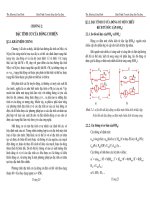
For human comfort and building health, A/C is commonly expected to maintain a humidity level
of less than 60% and inside the ASHRAE comfort zone (ASHRAE Standard 55-2004) seen in
Figure 2-1. The comfort zone is only a general requirement and may be strongly influenced by
occupant activity and clothing level. The summer zone is primarily for sedentary activity with a
t-shirt and trousers. Often, temperatures are set to lower set points because activity generally
increases. The winter zone is for significantly heavier clothing, but still sedentary activity. The
60% relative humidity (RH) line does intersect the comfort zones, and thus influences how the
A/C must react to provide proper building indoor air quality despite human comfort concerns.
3
Psychrometric Chart at 0 ft Elevation (1.013 bar)
(14.7 psia)
Psychrometric Chart at 0 ft Elevation (14.7 psia)
160
Comfort Zone (Summer)
Comfort Zone (Winter)
60%
50 60 70 80 90 100
140
120
100
ω (grains/lb)
80
60
40
20
0
Dry Bulb Temperature (
°F)
Figure 2-1 ASHRAE comfort zone and 60% RH limit for indoor air quality
Two types of space loads affect building humidity and temperature:
• Sensible load. This is the addition of heat to the building space and comes from a variety
of sources (e.g., sunlight, envelope, people, lights, and equipment).
• Latent load. This is the addition of moisture to the building space and comes from
multiple sources (e.g., infiltration, mechanical ventilation, and occupant activities).
Sensible and latent loads combined form the total load. The sensible load divided by the total
load is the sensible heat ratio (SHR). A line of constant SHR is a straight line on a
psychrometric chart, indicating simultaneous reduction in temperature and humidity. The
building loads determine the SHR and an air conditioner must react to it accordingly to maintain
temperature and humidity. To match the space load, an A/C system must provide air along a
constant SHR originating from the space condition (76°F and varying RH). To meet an SHR of
0.7, one must follow the SHR line of 0.7 to a delivery condition that is lower in temperature and
humidity. Figure 2-2 and Figure 2–3 show the implications of space SHR on an A/C system by
illustrating how 60% and 50% RH levels influence A/C performance. Humidity is typically
removed by cooling the air below the room air dew point. Thus, the saturation condition (black
line at 100% RH) is the potential to dehumidify. The intersection of the SHR lines and the
saturation line gives the “apparatus dew point” at which the cooling coil will operate. Reducing
RH from 60% to 50% requires that the apparatus dew point change from 56°F to 47°F at a
constant SHR of 0.7. When the SHR drops below 0.6 (which is typical of summer nights and
swing seasons when sensible gains are low), the humidity cannot be maintained below 60% RH
with standard DX cooling alone.
4
Psychrometric Chart at 0 ft Elevation (1.013 bar)
Psychrometric Chart at 0 ft Elevation (14.7 psia)
150
125
100
75
50
25
0
Dry Bulb Temperature (°F)
Figure 2-2 SHR lines plotted on a psychrometric chart with room air at 76°F and 60% RH
2.2 How Direct Expansion Air-Conditioning Achieves Performance Goals
For most of the A/C market, refrigeration-based (DX) cooling is the standard, and provides a
point of comparison for new technologies. To describe the benefits and improvements of
DEVap A/C technology, we must discuss standard A/C.
Standard A/C reacts to SHR by cooling the air sensibly and, if dehumidification is required, by
cooling the air below the dew point. This removes water at a particular SHR. Maintaining a
space at 76°F and 60% RH (see Figure 2-2) requires the A/C to deliver air along the relevant
SHR line. If the SHR line does not intersect the saturation line (as in the case of SHR = 0.5),
standard DX A/C cannot meet latent load, and the RH will increase. If humidity is maintained at
50% RH (Figure 2–3), standard DX A/C cannot maintain RH when the space SHR reaches
below about 0.7.
Building simulation results provide insight into typical SHRs in residential and commercial
buildings. Table 2–1 shows typical SHR ranges in a few U.S. climates. Humidity control with
standard DX A/C becomes an issue in climate zones 1A–5A and 4C. Thus, humidity control
must be added. Western climates in the hot/dry or hot/monsoon climates have sufficiently high
SHR and generally do not require additional humidity control.
Table 2-1 SHRs of Typical Climate Zones (ASHRAE Zones Noted)
Return or Room Air
40 50 60 70 80 90 100
ω (grains/lb)
Climate
Typical SHR Range
1A–3A. Hot/Humid (e.g., Houston)
0.0–0.9
4A–5A. Hot/Humid/Cold (e.g., Chicago)
0.0–1.0
2B. Hot/Monsoon (e.g., Phoenix)
0.7–1.0
3B–5B: Hot/Dry (e.g., Las Vegas)
0.8–1.0
4C. Marine (e.g., San Francisco)
0.5–1.0
5
In the A/C industry, common technologies for meeting lower SHRs are:
1. DX + wrap-around heat exchanger or latent wheel
o Trane CDQ (wrap-around active/desiccant wheel) (see Trane 2008)
o Munters Wringer (wrap-around sensible wheel) (see Munters Web site
www.munters.us/en/us/)
2. DX + active wheel
o Munters DryCool system using condenser reheat to reactivate an active desiccant
wheel (see Munters Web site www.munters.us/en/us/)
3. DX + reheat
o Lennox Humiditrol with condenser reheat (see Figure 2-3)
4. DX + ice or apparatus dewpoint < 45°F
o Four Seasons
o Ice Energy Ice Bear energy storage module (see Ice Energy 2010)
5. DX + space dehumidifier
Figure 2-3 Lennox DX A/C with Humiditrol condenser reheat coil (Lennox Commercial 2010)
Humidity control options for various building types are shown in Table 2-2.
Table 2-2 Technology Options for Residential and Commercial Buildings
Building Type
New and Retrofit
Residential 3. DX + reheat
5. DX + space dehumidifier
Commercial
1. DX + wrap-around heat exchanger
2. DX + active wheel
3. DX + reheat
4. DX + ice or apparatus dew point < 45°F
5. DX + space dehumidifier
Commercial buildings can, in most cases, use all technology options. Residential systems align
with options 3 and 5. These technologies do not come without penalties, which are always
increased energy use and added upfront costs. With options 1 and 2, the primary energy use
6
comes from significant increase in fan power to blow air through the various wheel types.
Option 3, DX + reheat, is the most common, but essentially erases the cooling done by the DX
circuit without significant DX cycle efficiency change. This creates an air conditioner rated at 3
tons that delivers 30% less cooling (or about 2 tons) with the same energy use as the original 3-
ton system. DX + apparatus dew point < 45°F has reduced cycle efficiency because deep
cooling is provided. DX + dehumidifier is much like DX + reheat, but the dehumidifier is a
specialized DX system used to deeply dry the air before reheating.
Options 1, 2, and 4 are usually chosen to pretreat outdoor air (OA) in a dedicated outdoor air
system, which in all but a few special cases (commercial kitchens and supermarkets with large
exhaust flows) will not control indoor humidity. However, these technologies do meet large load
profiles and can reduce the latent load requirements on the smaller DX systems serving the same
spaces. For space humidity control, most people choose DX + reheat for commercial spaces and
DX + reheat or dehumidifier for residential spaces. In all cases, latent cooling follows sensible
cooling. Thus, sensible cooling is often too high and must either be reheated or combined with a
desiccant to lower the SHR.
Table 2-3 Source Energy Efficiency Comparison for Commercial Equipment
(Kozubal 2010)
DX With Sensible DX With Desiccant DX With Wrap-
Humidity Level Gas Reheat Rotor and Condenser Around Desiccant
(dry bulb/wet bulb)
(200 cfm/ton)
Heat Regeneration
Rotor
High humidity (87°/77.3°F) 65% 75% N/A
Medium humidity (80°/71°F) 55% 65% 85%
Modest humidity (80°/68°F) 48% 46% 83%
2.3 The DEVap Process
2.3.1 Commercial-Grade Liquid Desiccant Air Conditioner Technology
Desiccants reverse the paradigm of standard DX A/C by first dehumidifying, and then sensibly
cooling to the necessary level. Desiccant at any given temperature has a water vapor pressure
equilibrium that is roughly in line with constant RH lines on a psychrometric chart (Figure 2-4).
The green lines show the potential for two common types of liquid desiccants, lithium chloride
(LiCl) and calcium chloride (CaCl
2
). If the free surface of the desiccant is kept at a constant
temperature, the air will be driven to that condition. If used with an evaporative heat sink at 55°–
85°F, the air can be significantly dehumidified and dew points < 32°F are easily achieved. The
blue arrow shows the ambient air being driven to equilibrium with LiCl with an evaporative heat
sink. At this point, the air can be sensibly cooled to the proper temperature. This type of
desiccant A/C system decouples the sensible and latent cooling, and controls each independently.
During the dehumidification process, the liquid desiccant (about 43% concentration by weight
salt in water solution) absorbs the water vapor and releases heat. The heat is carried away by a
heat sink, usually chilled water from a cooling tower. As water vapor is absorbed from the
ambient air, it dilutes the liquid desiccant and decreases its vapor pressure and its ability to
absorb water vapor. Lower concentrations of desiccant come into equilibrium at higher ambient
air RH levels. Dehumidification can be controlled by the desiccant concentration that is supplied
to the device. The outlet humidity level can be controlled by controlling the supplied desiccant
concentration or decreasing the flow of highly concentrated desiccant. The latter allows the
7
8
highly concentrated desiccant to quickly be diluted and thus “act” as a weaker desiccant solution
in the device.
Figure 2-4 Psychrometric chart showing the dehumidification process using desiccants
Absorption will eventually weaken the desiccant solution and reduce its dehumidifying potential;
the desiccant must then be regenerated to drive off the absorbed water. Thermal regeneration is
the reverse: In this process, the desiccant is heated to a temperature at which the equilibrium
vapor pressure is above ambient. The vapor desorbs from the desiccant and is carried away by
an air stream (see Figure 2-5). Sensible heat is recovered by first preheating the ambient air
using an air-to-air heat exchanger (AAHX). The air comes into heat and mass exchange with the
hot desiccant (in this example at 190°F) and carries the desorbed water vapor away from the
desiccant. Sensible heat is recovered by taking the hot humid air to preheat the incoming air
through the AAHX. The change in enthalpy of the air stream represents the majority of the
thermal input. Small heat loss mechanisms are not represented in the psychrometric process.
The process uses hot water or steam to achieve a latent coefficient of performance (COP) of 0.8–
0.94 depending on ultimate desiccant concentration. Latent COP is defined as:
COP is maximized by maximizing the regeneration temperature and change in concentration
while minimizing the ultimate desiccant concentration. Including the COP of the water heater
(about 0.82), a typical combined latent COP is 0.82 × 0.85 = 0.7.
0
20
40
60
80
100
120
140
160
30 40 50 60 70 80 90 100 110 120
ω (grains/lb)
Dry Bulb Temperature (°F)
Psychrometric Chart at 0 ft Elevation (1.013 bar)
Room or Return Air
(14.7 psia)
Psychrometric Chart at 0 ft Elevation (14.7 psia)
Psychrometric Chart at 0 ft Elevation (1.013 bar)
(14.7 psia)
Psychrometric Chart at 0 ft Elevation (14.7 psia)
1000
30 40 50 60 70 80
90 100 110 120 130
140 150 160 170 180 190 200 210
Enthalpy = 45 BTU/lbm
Enthalpy = 60.6 BTU/lbm
Enthalpy = 192.5 BTU/lbm
Ambien t Air
SR Exhaust Air
Majority of
Heat Input
900
800
700
600
500
400
ω (grains/lb)
300
200
100
0
Dry Bulb Temperature (°F)
Figure 2-5 Desiccant reactivation using single-effect scavenging air regenerator
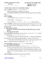
The AILR LDAC technology uses novel heat and mass exchangers (HMXs) to perform these
two processes (see Figure 2-6), which show the desiccant conditioner and scavenging air
regenerator. The liquid desiccant is absorbed into the conditioner (absorber) where the inlet
ambient air is dehumidified. The liquid desiccant is regenerated in the regenerator (desorber)
where the water vapor desorbs into the EA stream. This technology is called low flow liquid
desiccant A/C, because the desiccant flow is minimized in both HMXs to the flow rate needed to
absorb the necessary moisture from the air stream. The HMXs must therefore have integral
heating and cooling sources (55°–85°F cooling tower water is supplied to the conditioner). The
regenerator uses hot water or hot steam at 160°–212°F. The cooling or heating water flows
internal to the heat exchange plates shown. The desiccant flows on the external side of the HMX
plates. The plates are flocked, which effectively spreads the desiccant. This creates direct
contact surfaces between the air and desiccant flows. The air passes between the plates, which
are spaced 0.25 in. apart. Figure also shows a 20-ton packaged version on a supermarket in
Los Angeles, California. Lowenstein (2005) provides more detailed descriptions of these
devices.
9
cool, dry ventilation
Regenerator
delivered to building
Cooling Tower
Water heater
Conditioner
Economizer
hot and
humid
air
humid
exhaust
heating
water
chilled
water
Figure 2-6 Major components and packaging of the AILR LDAC (Photograph shows packaged
HMXs, water heater and cooling tower)
(Photos used with permission from AIL Research)
A double-effect regenerator expands on the scavenging air regenerator by first boiling the water
out of the liquid desiccant solution (250°–280°F) and reusing the steam by sending it through the
scavenging air regenerator. This two-stage regeneration system can achieve a latent COP of 1.1–
1.4. NREL is working with AILR to develop this product. A typical solar regenerator would
consist of either a hot water supply to a scavenging regenerator (which would result in a single-
effect device that would have about a 60% solar conversion efficiency based on absorber area).
We are currently monitoring more advanced concepts that generate steam by boiling either water
or liquid desiccant internal to a Dewar-style evacuated tube. If filled with water to create steam,
efficiency up to 70% is possible. An advanced version would boil desiccant directly in the solar
collector to create steam that is then used in the scavenging regenerator. This would increase
solar conversion efficiency to 120%. This work is ongoing and results are not yet available.
Table 2-4 Technology Options for Residential and Commercial Buildings
(Based on NREL calculations and laboratory data, available on request)
Regenerator
COP
Solar
60%–120% solar conversion
Single effect*
0.7–0.8
Double effect*
1.1–1.4
* Based on the higher heating value of natural gas
For the low-flow LDAC, the regenerator and conditioner systems are shown connected in Figure
2-7, which illustrates the three basic ways to regenerate the desiccant system with a thermal
source: solar, water heater, and a double effect. The water heater or boiler can be fueled by
many sources, including natural gas, combined heat and power (CHP), or even biofuels.
Also shown is the desiccant storage option that allows an A/C system to effectively bridge the
time gap between thermal energy source availability and cooling load. Desiccant storage at 8%
concentration differential will result in about 5 gal/latent ton·h. In comparison, ice storage is
approximately 13–15 gal/ton·h (theoretically 10 gal/ton·h, but in practice only 67% of the
10