3D in Photoshop The Ultimate Guide for Creative Professionals PHẦN 4 pot
Bạn đang xem bản rút gọn của tài liệu. Xem và tải ngay bản đầy đủ của tài liệu tại đây (1006.28 KB, 23 trang )
5.4.1. Ground Shadows and Snapping Object
to Ground Plane
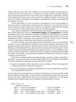
Ground shadows can be created by turning on the option in the 3D menu or
in the fly-out of the 3D Scene panel. This option will generate shadows on the
ground plane of your scene where the plane is always “invisible. ” This serves
as an invisible shadow catcher for your 3D layer (Figure 5.8).
Often your object may be too far from your ground plane for the ground
plane to catch the shadow. If this occurs, you can use the “Snap the Object to
Ground Plane” command from the 3D menu, which will snap the closest
point of your 3D object to the ground plane.
Note: Remember that in order to see shadows you have to be in Ray Trace
Draft or Final mode.
FIG 5.8 Shadow cast on the ground plane of the scene. This functions as an invisible shadow catcher (plane) for your object.
|
3D in Photoshop
50
5.5. Colored Transparent Shadows
In the image below, we have a scene with a plane on the ground which will
catch the shadows, an opaque window frame, an opaque glass object and
a point light placed behind the window (indicated by the white Light overlay
widget). The shadow that is cast in this configuration is a completely black
shadow:
If we set the window's Opacity to 50%, we get the following image:
Lights, Shadows and Final Rendering
|
51
As you can see, a semi-transparent shadow is cast and the window is semi-
transparent. Now let's try to get some color in that shadow. If we set the
diffuse color of the glass object to red (255, 0, 0). We get the following image:
Note that the shadow on the ground is tinted red. But why isn't the glass
itself red? This is because the light is behind the glass pane so when the Ray
Tracer does its lighting calculation, it gets back black. In this particular
scenario if we want the glass pane to also be red, we must set it to red using
the self-illumination parameter. Setting the Self-Illumination to red we get
the following image:
|
3D in Photoshop
52
Although this seems like a lot of steps to get the desired result, it does allow
the user a great level of flexibility by being able to control the color of the
shadow vs. the color of the transmitted light separately.
Now let's consider a different scenario in which the light is moved in front of
the window pane. Now you can set the Self-Illumination back to 0 and, with
the same Opacity of 50% from before, we get the expected behavior e a red
shadow with a red pane:
When the light is positioned in front of the object, both the object and the
shadow accuratelyrespondto thepropertiesof thelightandreflecttheredcolor.
When the light was positioned behind the object, because Photoshop does not
support double-sided lighting, the object did not respondto the reflection ofthe
light and therefore, the effect was mimicked using self-illumination.
Now let's set the Opacity of the window to be 10%:
Lights, Shadows and Final Rendering
|
53
The window becomes more transparent and the redness in the shadow is
reduced. Now let's set the Opacity to 85%:
The window becomes brighter red and the shadow gets darker. So, how do I
get a bright red (255, 0, 0) shadow? Unfortunately, this is not going to be
possible in the current version of Photoshop. With a 50% Opacity you will get
a shadow that is 50% the diffuse color of the object casting the shadow. As
the opacity increases, the shadow will get darker. As the opacity decreases
the shadow will get lighter. However, the color of the shadow will never be
the same color as the object that is casting the shadow.
One potential work-around in the case where the glass object is back-lit as it
was originally would be to create a 32-bit diffuse texture and set the color
brighter (i.e., 2.0, 0, 0 for red instead of 1, 0, 0). However, this work-around will
not work if the object is front-lit. Another work-around is to increase the
intensity of the lights. This has the side effect that the entire scene's illumi-
nation is also increased e which may be undesirable.
It is also possible to do stained glass effects by using the same texture for the
self-illumination map as the diffuse map:
|
3D in Photoshop
54
Tip: Shadows During Interaction. It can often be very useful to see your
shadows change as you interact with your scene. This can be achieved using
the Adobe Ray Tracer (Draft or Final), which must be turned on using the
settings in the 3D Preferences panel. See Chapter 2 Ray Tracing and the
section before this (5.4 Adding and Editing Shadows) for more information
on how to do this.
5.6. Final Rendering
Rendering your final scene is an important step in the 3D design process e as
it is the only way you can see many of the advanced effects Photoshop has to
offer. Photoshop has a Ray Tracer that renders all the final lighting, shadows,
reflections and refractions. For more detailed information on the Ray Tracer,
see Chapter 2.
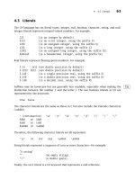
Rendering with the Ray Tracer can be set from the 3D Scene panel under the
Quality menu. There are two modes of Ray Trace rendering e Draft and Final.
Draft will be quicker than Final and will give you a general idea of how your
final lighting will look. The amount of time it takes for final rendering to be
complete is dependent on many factors including the resolution of the
document, how complex your scene is and what quality maximum is set from
the 3D section in Preferences (Figure 5.9).
FIG 5.9 Go to the 3D section in Preferences to set “High Quality Threshold” for Final Ray Tracing.
Lights, Shadows and Final Rendering
|
55
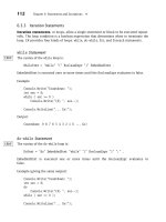
In Photoshop CS5 Extended, progressive rendering was added for the Adobe
Ray Tracer. This means that your scene will be rendered progressively, or in
stages (a certain number of passes), allowing you to quickly get an initial feel
of what your lighting will look like as an indication that rendering is
incomplete. At any stage of rendering, Photoshop will draw a grid overlaying
the area that is currently being rendered. When rendering is complete, the
grid (tiles) are no longer drawn (Figure 5.10).
You can pause your render at any time by clicking the mouse or by pressing
the spacebar or Esc key. To resume the render, choose 3D > Resume
Progressive Render from the 3D menu or from the 3D flyout in the panel.
5.6.1. Test Rendering
Photoshop can test render any selection easily. This means that you can take
any part of your 3D scene and only render that section. For instance, it is
useful to run a test rendering on shadows if you have a particularly complex
lighting setup where you may want to see how shadows are rendering.
Simply make a selection around the area you want to be rendered and run
the command “3D > Progressive Render Selection”. This is important if you
don't want to wait for the whole scene to render before knowing what
a certain part of your scene will look like.
FIG 5.10 Blue grid overlay showing you areas in the scene that are getting rendered. In the image on the right,
most of the orange itself is fully rendered (no grid drawn) whereas the shadow (grid overlay drawn) is still
rendering.
|
3D in Photoshop
56
Adobe Repoussé e
3D Extrusions
6.1. Introduction to Adobe Repoussé
Adobe Repoussé is a feature that allows you to produce a 3D shape from
closed paths. It is named after the metalworking technique of shaping
a metal by hammering a pattern from the reverse side.
The Adobe Repoussé feature can be invoked from the 3D panel in Photoshop
or from the 3D menu.
Adobe Repoussé relies on OpenGL Drawing. This means that you must have
a GPU (video card) that is compatible with Photoshop CS5 Extended. If your
video card doesn't support OGL Drawing in Photoshop, the Repoussé menu
item in the 3D menu will be grayed out and Repoussé will not work. For more
information on OpenGL, see Chapter 2: Section 2.1.
Repoussé can be invoked on one of four types of objects: text layer, layer
mask, selection or path (Figure 6.1). Repoussé converts the paths from each
of the input types into an editable collection of surfaces called a Repoussé
CHAPTER 6
|
3D in Photoshop. DOI: 10.1016/B978-0-240-81377-6.10006-7
Copyright Ó 2010 Elsevier Inc. All rights reserved.
57
patch. The area bounded by the input path forms the front of the Repoussé
patch. The front is surrounded by the front bevel surface. The Repoussé patch
also has a back and back bevel surface opposite the front and front bevel
surface respectively. Finally, the extrusion connecting the front bevel to the
back bevel is the side surface (Figure 6.2).
In the Repoussé dialog, you can independently change the shape of all five
surfaces of the Repoussé patch. Similarly, you can independently set material
properties for all five surfaces of the Repoussé patch. Any of the changes
made in the Repoussé panel will be immediately previewed on the docu-
ment canvas. The Repoussé patch can be transformed directly on the Pho-
toshop canvas by the usual mesh transformation tools or the 3D-Axis Widget
(Figure 6.3). Hitting Cancel in the Repoussé panel will undo these changes
and close the Repoussé panel.
The main controls for the Repoussé object are found in the Repoussé dialog
(see Figure 6.4).
FIG 6.1 Repoussé can be invoked from the 3D panel or from the 3D menu.
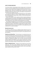
FIG 6.2 Starting with the letter R, Adobe Repoussé is used to extrude it to a 3D text object. The Repoussé object
consists of a front and back surface, a front and back bevel and a side extrusion.
|
3D in Photoshop
58
FIG 6.3 Use the Mesh rotation tools located on the side of the Repoussé dialog or use the 3D Axis Tool on canvas
to reposition your object.
FIG 6.4 The Repoussé dialog
A e 3D Mesh controls to rotate, roll, pan, slide, scale and to revert to default position. B e Shape presets to
change geometry. C e Extrude parameters. D e Inflate parameters that can be applied to Front and/or Back
faces. E e Constraint controls to set parameters for internal subpaths (or selections). F e View 3D overlays
including 3D-Axis Tool, Mesh boundaries, Lights and Ground Plane. G e Material libraries and picker for the
different Repoussé surfaces. H e Bevel parameters that can be applied to Front and/or back faces. I e Scene
Settings where you can select Light presets, Saved Mesh positions, Render Settings and Mesh Quality.
Adobe Repoussé e 3D Extrusions
|
59
There are three properties you can change using the Repoussé dialog: Shape,
Materials and Rendering. Of these, the Shape changes are the only ones
unique to the Repoussé dialog; you can change Material, Positioning,
Lighting and Rendering properties from the 3D panel (Window > 3D) outside
the Repoussé dialog as well.
Many of the scene navigation tools from the 3D panel are also provided in
the Repoussé dialog for your convenience. As shown in Figure 6.4, you can
cycle through Light presets, observe the Repoussé patch from different
viewpoints and change the Render settings. In addition, in the bottom left of
the dialog, you'll see toggle switches for displaying the 3D Mesh overlays,
Ground Plane, Lights and the 3D-Axis Widget. This is the same Overlay menu
you get in the 3D panel ( Figure 6.5).
6.2. Changing the Repous sé Shape
6.2.1. Presets
The quickest way to significantly alter the default 3D shape is to choose one
of the Repoussé presets from the top-left section of the Repoussé panel.
These presets are pre-determined combinations of extrusion, bevel and
inflation parameters (which are described below). After selecting a preset, it
can be further fine-tuned by changing individual parameters. Additionally,
you can save your preferred combination of individual Repoussé parameters
as a custom preset from the fly-out menu in the Repoussé presets section.
Extrusion, Depth, Twist, and Scale
The extrusion (side) surface can be made longer by changing the Depth
slider. This parameter controls the amount of extrusion and is commonly
found in other 3D modeling applications. The extrusion can also be twisted
by changing the twist angle. The twist angle specifies the total twist between
the front and the back surfaces and is distributed evenly along the extrusion
surface. Finally, the extrusion can be scaled so the back surface is a scaled
FIG 6.5 The 3D Overlay toggles
found in the Repoussé dialog are
also found in the 3D Scene panel.
FIG 6.6 A e Simple extrusion applied to the letter R. B e Scale applied where the back face is scaled larger than the front face. C e Scale applied where
the back face is scaled smaller than the front face. D e Simple twist applied to the letter R.
|
3D in Photoshop
60
version of the front surface, with the extrusion surface smoothly growing or
shrinking to connect the front to the back (Figures 6.6 and 6.7).
Bend and Shear
In Repo ussé, you can create cu rved extrusions by applying a bend to the
extrusion as well as a shear effect (where the front and back surfaces move
parallel to each other). To simulate a lathe using Repoussé (Figure 6.8), pick
an X bend angle of 360 degrees and change the reference point to lie on
the rig ht edge of the bounding box (any one of the three points ). To lathe in
the opposite direction, pic k an X bend angle of À360 degrees and pick the
FIG 6.8 A e A simple bend to the left applied with an extrusion depth of 1. B e A simple bend to the left applied with a 0 extrusion depth and
a reference point set to be the center left. C e A 360 degree bend applied to the letter R. This simulates what is commonly referred to as a lathe.
FIG 6.7 Variety of different extrusion parameters applied.
Adobe Repoussé e 3D Extrusions
|
61
reference point to lie on the left edge of th e bounding box. For a smooth
curve, make sure that you have your Mesh Quality set to high for more
informationonthis,refertoSection6.5inthisChapter.
A powerful method for generating a vast variety of shapes is to change the
reference point for all of the above extrusion parameters. The reference point
is a temporary ‘origin’ point used by the extrusion twist, scale and bend
operations to measure distances. By default, the reference point is the center
of the 2D bounding box of the input path. However, you can change the
reference point to be on the edge of the bounding box, or even on one of the
corners. Changing the reference point changes the way in which the twist,
scale and bend extrusion parameters control the shape, so you can produce
drastically different shapes by simply changing the reference point.
Bevel
Beveling allows you to simulate a process that cuts away the boundary edges
that the Repoussé shape forms along the boundaries of the front and back
surfaces. To expose the bevel surfaces, move the Width and Height sliders e
the height can be positive (where the front or back surface is pushed out) or
negative (where the front or back surface is pushed in). The bevel surface is
hidden when its width is zero. By default, the beveled edge is a straight line
(Linear preset) and flat. However, it can be set to any preset contour shapes
(Figure 6.9 and 6.10).
Clicking on the contour thumbnail
will bring up a bevel profile editor that
allows you to construct custom contours in the same way that you would in
the Bevel and Emboss section of the Layer Effects dialog. The bevel mesh will
update interactively as you change the bevel profile contour.
Inflation
A unique ability in Repoussé is to smoothly inflate or “puff out” the front or
back surfaces. Inflating the surface gives a unique 3D look to the originally
flat surface (Figure 6.11).
FIG 6.9 A e Default settings with no bevel applied (0 height and width). B e Simple Linear preset bevel applied. C e Simple Cone preset applied.
|
3D in Photoshop
62
FIG 6.10 Custom bevel applied using the Contour editor (found by clicking on the profile thumbnail in the Repoussé dialog).
FIG 6.11 Smooth inflation applied to
the front of this letter R.
Adobe Repoussé e 3D Extrusions
|
63
The front or back surface is inflated by changing the angle it makes at the
boundary. Additionally, you can change the strength with which the angle
condition must be maintained. A high strength value will propagate the
angle requirement further from the boundary; zero angle and strength will
have the default flat behavior.
Note that inflation can be performed only on the front and back surfaces, and
the bevel and extrusion surfaces are unchanged during the inflation
parameter changes.
6.3. Constraints
Constraints are internal paths fully contained within closed paths. If you take
a look at the example we've been using with the letter R, there is an internal
constraint identified as the hole in this letter. Note that fonts are treated
specially in Repoussé where the holes are automatically identified. However,
for all other paths or selections, you have the option to select the constraint
to be a hole or to be filled (Figure 6.12). For more information on creating
holes with Repoussé see below.
These internal paths may exist in the input paths originally provided to
Repoussé, or additional constraints may be added at any time to the front
Repoussé patch. To add constraints to an existing Repoussé patch, the user
first draws paths or selections from outside the Repoussé panel. After
drawing the paths or selections, add them as constraints from the Repoussé
sub-menu of the 3D menu or from the Internal Constraints drop-down
section of the Repoussé panel (Figures 6.13). Only paths that are fully con-
tained within the front surface and do not intersect existing constraints or
boundaries can be added as new constraints.
FIG 6.12 A e For text, by default Photoshop will defi ne constraints (blue dotted line) to be a hole. B e This
same constraint can be changed to a filled constraint (‘active’) where separate extrusion parameters can be
applied relative to the bounding path or selection.
|
3D in Photoshop
64
Constraints are used as handles for modifying the front surface of the
Repoussé patch. The constraints can be manipulated directly by the
constraint tools. The rest of the surface will smoothly deform to pass through
the constraints. The shape of the surface near constraints can further be
modified by using the angle and strength parameters and behave similar to
the parameters used to inflate the surface.
6.3.1. Holes
The most common type of constraint is the “hole” constraint. Fonts are
treated specially in Repoussé where the holes are automatically identified.
For example, with the letter “R” the inside of the R is automatically detected
as a hole and will be “punched-out”. Whenever a hole is added to the front
surface, one automatically is added to the back. Therefore, you will be able to
see through both the front and the back face to the background. Similarly,
when you change the position of the hole on the front, a similar change will
happen to the hole on the back. Since the hole is on the boundary of the
surface, when you change the patch-wide inflation parameters, the surface
will be inflated near the hole as well. The hole can be converted into an active
constraint or an inactive constraint (Figure 6.15). For a constraint to be made
into or added as a hole, it must be a closed path.
FIG 6.14 Constraints can be added using the Internal Constraints controls found at the bottom of the Repoussé
dialog and hitting the Add (Selection) and Add (Path) buttons.
FIG 6.13 Constraints can be added to existing Repoussé patches in the 3D menu as well as by using the
Constraints controls in the Repoussé dialog (see Figure 6.14).
Adobe Repoussé e 3D Extrusions
|
65
6.3.2. Active Constraints
Active constraints affect the surface on both sides of the path. Like holes,
active constraints can be moved, and the surface near the active constraint
can be further inflated using the angle and strength parameters. The inflation
parameters can be independently varied on either side of the constraint.
Unlike holes, active constraint when added to the front, are not added to the
back surface. Also unlike holes, active constraints can be open or closed
paths (Figure 6.16).
6.3.3. Inactive Constraints
Inactive constraints are placeholder constraints that have been “turned off.”
They are useful in cases where you may have too many internal constraints,
FIG 6.16 Distorting Photographs with Active Constraints
First, we convert this photograph to a 3D plane by selecting the whole image and creating a Repoussé patch. We then draw a polygon around the subject,
add it as an active constraint and move it up. The pixels inside the constraint are undistorted, and the pixels outside the constraint stretch to satisfy the new
constraint position.
FIG 6.15 The same letter “R” where the constraint in the middle is set as a “hole” and manipulated inde-
pendently from the existing bounding shape/path using the constraint rotation tools found at the bottom of the
Repoussé dialog (see Figure 6.4).
|
3D in Photoshop
66
and want to use only some of them. This may happen if you have a
complicated path with many internal sub-paths and you may not want to
individually manipulate all of them e some of the paths might remain
“inactive” or without any extrusion properties added. The inactive constraints
lie on the surface and are only modified by neighboring surface changes.
However, they do not affect the surface. Automatically making all sub-paths
active can cause performance degradation; therefore, Photoshop automati-
cally leaves sub-paths inactive until user changes it. Inactive constraints can
be changed to the active or hole type constraints at any time: the constraint
position will be set to its initial position and will need to be transformed using
the constraint tools to match their desired positions.
6.4. Assigning Materials
In addition to changing the shape of the Repoussé patch, you can also change
the material of any of the five patch surfaces. The material picker in the
top-right section of the Repoussé panel is used for high-level material speci-
fication. The material of any of the five surfaces can be specified by clicking the
drop-down thumbnail icon for the corresponding surface. The same material
can be applied to all five surfaces by clicking the thumbnail labeled “All.”
6.4.1. Extrusion Texture Mapping
As described earlier, materials often contain texture maps that control the
appearance of the shape. The extrusion (side) surface has three options for
specifying the texture mapping method. These three options are “Scale,”
“Tile” and “Fill.” These options are found in the drop-down box labeled
“Texture” in the Extrude section of the Repoussé dialog (see Figure 6.4).
Scale
The Scale option scales the texture to exactly fit the extrusion, such that one
side of the texture map completely goes around the boundary, and the other
side of the texture map spans the entire depth of the extrusion.
Tile
The Tile option will assign the texture map without any scaling, and will tile
the texture if the extrusion surface area is greater than the texture area.
Fill
The Fill option will scale the texture such that the smaller dimension of the
texture map will exactly fit the larger dimension of the extrusion surface
(either perimeter of boundary or extrusion depth).
6.5. Mesh Quality
Some patches with highly curved extrusions, complicated bevel profiles,
large inflation angles or transformed constraints may look tessellated or
Adobe Repoussé e 3D Extrusions
|
67
“blocky.” Improving the mesh quality will reduce these tessellation artifacts.
In the Scene Settings section (see Figure 6.4) of the Repoussé dialog, you'll
see a Mesh Quality drop-down menu. Improving the mesh quality will
produce denser meshes with smaller triangles for all five Repoussé surfaces.
Since increasing the mesh quality produces denser meshes, you will notice
a slowdown in rendering and Repoussé parameter updates. You should not
set the quality to High until you are done editing the shape of your object.
6.5.1. Repoussé Speed
The speed with which Repoussé interacts to user input depends strongly on
the number of samples (points) of the input paths. A larger path will have
more samples. Similarly, a densely sampled path will have more samples. For
example, Repoussé will be much slower on a path drawn on a 300 ppi
document than for the same path drawn on a 72 ppi document. For large
documents, you can invoke Repoussé on a smaller path (to have faster
interaction speeds) and use the mesh scaling tools to expand the Repoussé
patch after exiting the Repoussé dialog.
6.6. Split Apart Functionality
You may invoke Repoussé on a string of text (or a number of disjoint paths)
and Photoshop will still produce a single Repoussé patch (or mesh). If you
want to break apart the different pieces of the patch into separate Repoussé
patches (or meshes), you can use the “Split Apart” functionality found in the
3D menu under Repoussé (Figures 6.17 and 6.18).
Alternatively, to achieve the same result you can start with separate meshes
or 3D layers initially and then later merge the object together. You will see
more on this later in Chapter 9.
FIG 6.17 The Split Repoussé Meshes command is useful if you would like to generate separate meshes for each
letter in a string of text or to separate disjointed objects where a single Repoussé object was created. Having
separate meshes will enable you to position the different letters (or objects) independently and enable you to
assign different materials to each object.
|
3D in Photoshop
68
FIG 6.18 String of text “ABC” where the single text layer was first created as a single Repoussé patch (top) and
then split apart (bottom) to independently manipulate the letter “B” from the others.
Adobe Repoussé e 3D Extrusions
|
69
and Optimization
7.1. 3D Preferences
The 3D preferences can be found in a Preference panel in the Preferences
dialog. It can be accessed by opening any Preference panel and selecting 3D
on the tab selector to the right, or it can be opened directly using Prefer-
ences > 3D menu item. Since many of the features in Photoshop 3D depend
on OpenGL, the GPU Memory, Interactive Rendering, 3D Overlays and
Ground Plane controls are only enabled when OpenGL is available and
turned on in the Performance preference tab (Figure 7.1).
Note: In order for Photoshop to communicate with your graphics card to
achieve accelerated 3D rendering, it must do so through a piece of software
called the graphics driver. This driver is usually provided by the manufacturer
of your video card but in some cases, such as certain laptops, it will be
provided by the laptop manufacturer. In order to assure that your 3D func-
tionality works properly, it is important that you have the most up-to-date
CHAPTER 7
|
3D in Photoshop. DOI: 10.1016/B978-0-240-81377-6.10007-9
Copyright Ó 2010 Elsevier Inc. All rights reserved.
71
graphics drivers for your hardware. For more information on graphics car see
Chapter 2, Section 2.1.
7.2. GPU Memory (VRAM)
In the upper-left corner of the 3D Preferences, you can change the total
amount of V RAM available for 3D features in Photos hop. VRAM is used by
your GPU card and is separate from your system memory (RAM). Settings
for general memory allocation are found in the Performance section
Photoshop Preferences (Figure 7.2). Video memory is also used by other
(non-3D) features within Photoshop that are dependent on OGL (i.e. Canvas
Rotation), other applications dependent on O GL as well as the operatin g
system; therefore, the VRAM setting in the 3D section of your Photoshop
Preferences only allocates a portion of the total VRAM available while
saving a certain (non-editable) amount of VRAM for capabilities outside of
3D in Photoshop. In other words, the operating system and other parts of
Photoshop are using som e of the installed VRAM, so the available amou nt is
goingtobelessthanthetotalamountthatyourGPUhas.Formostusers,
the default value set will be a ppropriate. However, there are two cases in
which change is necessary:
· Case 1: One or more GPU-dependent programs are running in parallel with
Adobe Photoshop, such as Adobe Premiere or a 3D modeling tool. If you
would like for them to have more GPU memory available, you should
reduce Photoshop's VRAM allotment.
· Case 2: Your 3D workflow involves a 3D model with many triangles and/or
large textures and no other GPU-dependent programs are running. To
ensure maximum performance, set the VRAM limit closer to its maximum.
FIG 7.1 3D Preferences found in Photoshop Preferences dialog.
FIG 7.2 Preferences to set general
Memory Usage in Photoshop.
|
3D in Photoshop
72