Advanced 3D Game Programming with DirectX - phần 4 ppsx
Bạn đang xem bản rút gọn của tài liệu. Xem và tải ngay bản đầy đủ của tài liệu tại đây (532.78 KB, 71 trang )
214
Now that know how to represent all of the transformations with matrices, you can concatenate them
together, saving a load of time and space. This also changes the way you might think about
transformations. Each object defines all of its points with respect to a local coordinate system, with the
origin representing the center of rotation for the object. Each object also has a matrix, which transforms
the points from the local origin to some location in the world. When the object is moved, the matrix can
be manipulated to move the points to a different location in the world.
To understand what is going on here, you need to modify the way you perceive matrix transformations.
Rather than translate or rotate, they actually become maps from one coordinate space to another. The
object is defined in one coordinate space (which is generally called the object's local coordinate space),
and the object's matrix maps all of the points to a new location in another coordinate space, which is
generally the coordinate space for the entire world (generally called the world coordinate space).
A nice feature of matrices is that it's easy to see where the matrix that transforms from object space to
world space is sitting in the world. If you look at the data the right way, you can actually see where the
object axes get mapped into the world space.
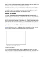
Consider four vectors, called n, o, a, and p. The p vector represents the location of the object
coordinate space with relation to the world origin. The n, o, and a vectors represent the orientation of
the i, j, and k vectors, respectively.
Figure 5.23: The n, o, a, and p vectors for a transformation
You can get and set these vectors right in the matrix, as they are sitting there in plain sight:
215
This system of matrix concatenations is how almost all 3D applications perform their transformations.
There are four spaces that points can live in: object space, world space, and two new spaces: view
space and screen space.
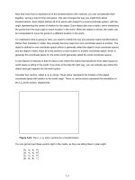
View space defines how images on the screen are displayed. Think of it as a camera. If you move the
camera around the scene, the view will change. You see what is in front of the camera (in front is
defined as positive z).
Figure 5.24: Mapping from world space to view space
The transformation here is different than the one used to move from object space to world space. Now,
while the camera is defined with the same n, o, a, and p vectors as defined with the other transforms,
the matrix itself is different.
In fact, the view matrix is the inversion of what the object matrix for that position and orientation would
be. This is because you're performing a backward transformation: taking points once they're in world
space and putting them into a local coordinate space.
As long as you compose the transformations of just rotations and translations (and reflections, by the
way, but that comes into play much later in the book), computing the inverse of a transformation is easy.
Otherwise, computing an inverse is considerably more difficult and may not even be possible. The
inverse of a transformation matrix is given below.
216
Warning
This formula for inversion is not universal for all matrices. In fact, the only matrices
that can be inverted this way are ones composed exclusively of rotations,
reflections, and translations.
There is a final transformation that the points must go through in the transformation process. This
transformation maps 3D points defined with respect to the view origin (in view space) and turns them
into 2D points that can be drawn on the display. After transforming and clipping the polygons that make
up the scene such that they are visible on the screen, the final step is to move them into 2D
coordinates, since in order to actually draw things on the screen you need to have absolute x,y
coordinates on the screen to draw.
The way this used to be done was without matrices, just as an explicit projection calculation. The point
<x,y,z> would be mapped to <x ′,y ′> using the following equations:
where xCenter and yCenter were half of the width and height of the screen, respectively. These days
more complex equations are used, especially since there is now the need to make provisions for z-
buffering. While you want x and y to still behave the same way, you don't want to use a value as
arbitrary as scale.
Instead, a better value to use in the calculation of the projection matrix is the horizontal field of view
(fov). The horizontal fov will be hardcoded, and the code chooses a vertical field of view that will keep
the aspect ratio of the screen. This makes sense: You couldn't get away with using the same field of
view for both horizontal and vertical directions unless the screen was square; it would end up looking
vertically squished.
Finally, you also want to scale the z values appropriately. In Chapter 8
, I'll teach you about z-buffering,
but for right now just make note of an important feature: They let you clip out certain values of z-range.
Given the two variables z
near
and z
far
, nothing in front of z
near
will be drawn, nor will anything behind z
far
.
To make the z-buffer work swimmingly on all ranges of z
near
and z
far
, you need to scale the valid z
values to the range of 0.0 to 1.0.
For purposes of continuity, I'll use the same projection matrix definition that Direct3D recommends in
the documentation. First, let's define some values. You initially start with the width and height of the
viewport and the horizontal field of view.
217
With these parameters, the following projection matrix can be made:
Just for a sanity check, check out the result of this matrix multiplication:
Hmm… this is almost the result wanted, but there is more work to be done. Remember that in order to
extract the Cartesian (x,y,z) coordinates from the vector, the homogenous w component must be 1.0.
Since, after the multiplication, it's set to z (which can be any value), all four components need to be
divided by w to normalize it. This gives the following Cartesian coordinate:
As you can see, this is exactly what was wanted. The width and height are still scaled by values as in
the above equation and they are still divided by z. The visible x and y pixels are mapped to [−1,1], so
before rasterization Direct3D multiplies and adds the number by xCenter or yCenter. This, in essence,
maps the coordinates from [−1,1] to [0,width] and [0,height].
With this last piece of the puzzle, it is now possible to create the entire transformation pipeline. When
you want to render a scene, you set up a world matrix (to transform an object's local coordinate points
into world space), a view matrix (to transform world coordinate points into a space relative to the
viewer), and a projection matrix (to take those viewer-relative points and project them onto a 2D surface
so that they can be drawn on the screen). You then multiply the world, view, and projection matrices
together (in that order) to get a total matrix that transforms points from object space to screen space.
218
Warning
OpenGL uses a different matrix convention (where vectors are column vectors, not
row vectors, and all matrices are transposed). If you're used to OpenGL, the
equation above will seem backward. This is the convention that Direct3D uses, so
to avoid confusion, it's what is used here.
To draw a triangle, for example, you would take its local space points defining its three corners and
multiply them by the transformation matrix. Then you have to remember to divide through by the w
component and voilá! The points are now in screen space and can be filled in using a 2D raster
algorithm. Drawing multiple objects is a snap, too. For each object in the scene all you need to do is
change the world matrix and reconstruct the total transformation matrix.
The matrix4 Structure
Now that all the groundwork has been laid out to handle transformations, let's actually write some code.
The struct is called matrix4, because it represents 4D homogenous transformations. Hypothetically, if
you wanted to just create rotation matrices, you could do so with a class called matrix3. The definition of
matrix4 appears in Listing 5.23
.
Listing 5.23: The matrix4 structure
struct matrix4
{
/**
* we're using m[y][x] as our notation.
*/
union
{
struct
{
float _11, _12, _13, _14;
219
float _21, _22, _23, _24;
float _31, _32, _33, _34;
float _41, _42, _43, _44;
};
float m[4][4];
};
// justification for a function this ugly:
// provides an easy way to initialize static matrix variables
// like base matrices for bezier curves and the identity
matrix4(float IN_11, float IN_12, float IN_13, float IN_14,
float IN_21, float IN_22, float IN_23, float IN_24,
float IN_31, float IN_32, float IN_33, float IN_34,
float IN_41, float IN_42, float IN_43, float IN_44)
{
_11 = IN_11; _12 = IN_12; _13 = IN_13; _14 = IN_14;
_21 = IN_21; _22 = IN_22; _23 = IN_23; _24 = IN_24;
_31 = IN_31; _32 = IN_32; _33 = IN_33; _34 = IN_34;
_41 = IN_41; _42 = IN_42; _43 = IN_43; _44 = IN_44;
}
matrix4()
{
// Do nothing.
}
static const matrix4 Identity;
};
The code contains three main ways to multiply matrices. Two 4x4 matrices can be multiplied together;
this is useful for concatenating matrices. A point4 structure can be multiplied by a matrix4 structure; the
result is the application of the transformation to the 4D point. Finally, a specialization for multiplying
220
point3 structures and matrix4 structures exists to apply a non-projection transformation to a point3
structure. The matrix4*matrix4 operator creates a temporary structure to hold the result, and isn't terribly
fast. Matrix multiplications aren't performed often enough for this to be much of a concern, however.
Warning
If you plan on doing a lot of matrix multiplications per object or even per triangle,
you won't want to use the operator. Use the provided MatMult function; it's faster.
Listing 5.24: Matrix multiplication routines
matrix4 operator*(matrix4 const &a, matrix4 const &b)
{
matrix4 out; // temporary matrix4 for storing result
for(int j = 0; j < 4; j ++) // transform by columns first
for(int i = 0; i < 4; i ++) // then by rows
out.m[i][j] = a.m[i][0] * b.m[0][j] +
a.m[i][1] * b.m[1][j] +
a.m[i][2] * b.m[2][j] +
a.m[i][3] * b.m[3][j];
return out;
};
inline const point4 operator*( const matrix4 &a, const point4 &b)
{
return point4(
b.x*a._11 + b.y*a._21 + b.z*a._31 + b.w*a._41,
b.x*a._12 + b.y*a._22 + b.z*a._32 + b.w*a._42,
b.x*a._13 + b.y*a._23 + b.z*a._33 + b.w*a._43,
b.x*a._14 + b.y*a._24 + b.z*a._34 + b.w*a._44
);
};
inline const point4 operator*( const point4 &a, const matrix4 &b)
{
return b*a;
221
};
inline const point3 operator*( const matrix4 &a, const point3 &b)
{
return point3(
b.x*a._11 + b.y*a._21 + b.z*a._31 + a._41,
b.x*a._12 + b.y*a._22 + b.z*a._32 + a._42,
b.x*a._13 + b.y*a._23 + b.z*a._33 + a._43
);
};
inline const point3 operator*( const point3 &a, const matrix4 &b)
{
return b*a;
};
There are two ways to create each type of matrix transformation. One performs on an existing matrix4
structure (it doesn't create a temporary matrix4 structure, which is slow). The function for a
transformation x is void matrix4::Tox. The other is a static function designed to help write cleaner
looking code, not for speed. The format for these functions is static matrix4 matrix4::x.
Translation
Here again is the matrix for the translation transformation by a given point p:
The code to create this type of transformation matrix appears in Listing 5.25
.
Listing 5.25: Code to create a translation transformation
void matrix4::ToTranslation( const point3& p )
222
{
MakeIdent();
_41 = p.x;
_42 = p.y;
_43 = p.z;
}
matrix4 matrix4::Translation( const point3& p )
{
matrix4 out;
out.ToTranslation( p );
return out;
}
Basic Rotations
The matrices used to rotate around the three principal axes, again, are:
The code to set up Euler rotation matrices appears in Listing 5.26
.
Listing 5.26: Code to create Euler rotation transformations
void matrix4::ToXRot( float theta )
{
223
float c = (float) cos(theta);
float s = (float) sin(theta);
MakeIdent();
_22=c;
_23=s;
_32 = -s;
_33=c;
}
matrix4 matrix4::XRot( float theta )
{
matrix4 out;
out.ToXRot( theta );
return out;
}
//==========
void matrix4::ToYRot( float theta )
{
float c = (float) cos(theta);
float s = (float) sin(theta);
MakeIdent();
_11 = c;
_13 = -s;
_31 = s;
_33 = c;
}
matrix4 matrix4::YRot( float theta )
{
matrix4 out;
out.ToYRot( theta );
224
return out;
}
//==========
void matrix4::ToZRot( float theta )
{
float c = (float) cos(theta);
float s = (float) sin(theta);
MakeIdent();
_11 = c;
_12 = s;
_21 = -s;
_22 = c;
}
matrix4 matrix4::ZRot( float theta )
{
matrix4 out;
out.ToZRot( theta );
return out;
}
Axis-Angle Rotation
While there isn't enough space to provide a derivation of the axis-angle rotation matrix, that doesn't stop
it from being cool. Axis-angle rotations are the most useful matrix-based rotation. (I say matrix-based
because quaternions are faster and more flexible than matrix rotations; see Real-Time Rendering by
Tomas Moller and Eric Haines for a good discussion on them.)
There are a few problems with using just Euler rotation matrices (the x-rotation, y-rotation, z-rotation
matrices you've seen thus far). For starters, there really is no standard way to combine them together.
225
Imagine that you want to rotate an object around all three axes by three angles. In which order should
the matrices be multiplied together? Should the x-rotation come first? The z-rotation? Since no answer
is technically correct, usually people pick the one convention that works best and stick with it.
A worse problem is that of gimbal lock. To explain, look at how rotation matrices are put together. There
are really two ways to use rotation matrices. Method 1 is to keep track of the current yaw, pitch, and roll
rotations, and build a rotation matrix every frame. Method 2 uses the rotation matrix from the last frame,
by just rotating it a small amount to represent any rotation that happened since the last frame.
The second method, while it doesn't suffer from gimbal lock, suffers from other things, namely the fact
that all that matrix multiplication brings up some numerical imprecision issues. The i, j, and k vectors of
your matrix gradually become non-unit length and not mutually perpendicular. This is a bad thing.
However, there are ways to fix it that are pretty standard, such as renormalizing the vectors, using
cross-products to assure orthagonality.
Gimbal lock pops up when you're using the first method detailed above. Imagine that you perform a yaw
rotation first, then pitch, then roll. Also, say that the yaw and pitch rotations are both a quarter-turn (this
could come up quite easily in a game like Descent). So imagine you perform the first rotation, which
takes you from pointing forward to pointing up. The second rotation spins you around the y axis 90
degrees, so you're still facing up but your up direction is now to the right, not backward.
Now comes the lock. When you go to do the roll rotation, which way will it turn you? About the z axis, of
course. However, given any roll value, you can reach the same final rotation just by changing yaw or
pitch. So essentially, you have lost a degree of freedom. This, as you would expect, is bad.
Axis-angle rotations fix both of these problems by doing rotations much more intuitively. You provide an
axis that you want to rotate around and an angle amount to rotate around that axis. Simple. The actual
matrix to do it, which appears below, isn't quite as simple, unfortunately. For sanity's sake, just treat it as
a black box. See Real-Time Rendering (Moller and Haines) for a derivation of how this matrix is
constructed.
Code to create an axis-angle matrix transformation appears in Listing 5.27
.
Listing 5.27: Axis-angle matrix transformation code
void matrix4::ToAxisAngle( const point3& inAxis, float angle )
226
{
point3 axis = inAxis.Normalized();
float s = (float)sin( angle );
float c = (float)cos( angle );
float x = axis.x, y = axis.y, z = axis.z;
_11 = x*x*(1-c)+c;
_21 = x*y*(1-c)-(z*s);
_31 = x*z*(1-c)+(y*s);
_41 = 0;
_12 = y*x*(1-c)+(z*s);
_22 = y*y*(1-c)+c;
_32 = y*z*(1-c)-(x*s);
_42 = 0;
_13 = z*x*(1-c)-(y*s);
_23 = z*y*(1-c)+(x*s);
_33 = z*z*(1-c)+c;
_43 = 0;
_14 = 0;
_24 = 0;
_34 = 0;
_44 = 1;
}
matrix4 matrix4::AxisAngle( const point3& axis, float angle )
{
matrix4 out;
out.ToAxisAngle( axis, angle );
return out;
}
227
The LookAt Matrix
I discussed before that the first three components of the first three rows (the n, o, and a vectors) make
up the three principal axes (i, j, and k)of the coordinate space that the matrix represents. I am going to
use this to make a matrix that represents a transformation of an object looking a particular direction.
This is useful in many cases and is most often used in controlling the camera. Usually, there is a place
where the camera is and a place you want the camera to focus on. You can accomplish this using an
inverted LookAt matrix (you need to invert it because the camera transformation brings points from
world space to view space, not the other way around, like object matrices).
There is one restriction the LookAt matrix has. It always assumes that there is a constant up vector, and
the camera orients itself to that, so there is no tilt. For the code to work, the camera cannot be looking in
the same direction that the up vector points. This is because a cross product is performed with the view
vector and the up vector, and if they're the same thing the behavior of the cross product is undefined. In
games like Quake III: Arena, you can look almost straight up, but there is some infinitesimally small
epsilon that prevents you from looking in the exact direction.
Three vectors are passed into the function: a location for the matrix to be, a target to look at, and the up
vector (the third parameter will default to j <0,1,0> so you don't need to always enter it). The
transformation vector for the matrix is simply the location. The a vector is the normalized vector
representing the target minus the location (or a vector that is the direction you want the object to look
in). To find the n vector, simply take the normalized cross product of the up vector and the direction
vector. (This is why they can't be the same vector; the cross product would return garbage.) Finally, you
can get the o vector by taking the cross product of the n and a vectors already found.
I'll show you two versions of this transformation, one to compute the matrix for an object to world
transformation, and one that computes the inverse automatically. Use ObjectLookAt to make object
matrices that look in certain directions, and CameraLookAt to make cameras that look in certain
directions.
Listing 5.28: LookAt matrix generation code
void matrix4::ToObjectLookAt(
const point3& loc,
const point3& lookAt,
const point3& inUp )
{
228
point3 viewVec = lookAt - loc;
float mag = viewVec.Mag();
viewVec /= mag;
float fDot = inUp * viewVec;
point3 upVec = inUp - fDot * viewVec;
upVec.Normalize();
point3 rightVec = upVec ^ viewVec;
// The first three rows contain the basis
// vectors used to rotate the view to point
// at the lookat point
_11 = rightVec.x; _21 = upVec.x; _31 = viewVec.x;
_12 = rightVec.y; _22 = upVec.y; _32 = viewVec.y;
_13 = rightVec.z; _23 = upVec.z; _33 = viewVec.z;
// Do the translation values
_41 = loc.x;
_42 = loc.y;
_43 = loc.z;
_14 = 0;
_24 = 0;
_34 = 0;
_44 = 1;
}
matrix4 matrix4::ObjectLookAt(
const point3& loc,
const point3& lookAt,
const point3& inUp )
{
229
matrix4 out;
out.ToObjectLookAt( loc, lookAt, inUp );
return out;
}
//==========
void matrix4::ToCameraLookAt(
const point3& loc,
const point3& lookAt,
const point3& inUp )
{
point3 viewVec = lookAt - loc;
float mag = viewVec.Mag();
viewVec /= mag;
float fDot = inUp * viewVec;
point3 upVec = inUp - fDot * viewVec;
upVec.Normalize();
point3 rightVec = upVec ^ viewVec;
// The first three columns contain the basis
// vectors used to rotate the view to point
// at the lookat point
_11 = rightVec.x; _12 = upVec.x; _13 = viewVec.x;
_21 = rightVec.y; _22 = upVec.y; _23 = viewVec.y;
_31 = rightVec.z; _32 = upVec.z; _33 = viewVec.z;
// Do the translation values
_41 = - (loc * rightVec);
_42 = - (loc * upVec);
230
_43 = - (loc * viewVec);
_14 = 0;
_24 = 0;
_34 = 0;
_44 = 1;
}
matrix4 matrix4::CameraLookAt(
const point3& loc,
const point3& lookAt,
const point3& inUp )
{
matrix4 out;
out.ToCameraLookAt( loc, lookAt, inUp );
return out;
}
Perspective Projection Matrix
Creating a perspective projection matrix will be handled by the graphics layer when I add Direct3D to it
in Chapter 8
, using the matrix discussed earlier in the chapter.
Inverse of a Matrix
Again, the inverse of a matrix composed solely of translations, rotations, and reflections (scales such as
<1,1,−1> that flip sign but don't change the length) can be computed easily. The inverse matrix looks
like this:
Code to perform inversion appears in Listing 5.29
.
231
Listing 5.29: Matrix inversion code
void matrix4::ToInverse( const matrix4& in )
{
// first transpose the rotation matrix
_11 = in._11;
_12 = in._21;
_13 = in._31;
_21 = in._12;
_22 = in._22;
_23 = in._32;
_31 = in._13;
_32 = in._23;
_33 = in._33;
// fix right column
_14 = 0;
_24 = 0;
_34 = 0;
_44 = 1;
// now get the new translation vector
point3 temp = in.GetLoc();
_41 = -(temp.x * in._11 + temp.y * in._12 + temp.z * in._13);
_42 = -(temp.x * in._21 + temp.y * in._22 + temp.z * in._23);
_43 = -(temp.x * in._31 + temp.y * in._32 + temp.z * in._33);
}
matrix4 matrix4::Inverse( const matrix4& in )
{
232
matrix4 out;
out.ToInverse( in );
return out;
}
Collision Detection with Bounding Spheres
Up until now, when I talked about moving 3D objects around, I did so completely oblivious to wherever
they may be moving. But suppose there is a sphere slowly moving through the scene. During its journey
it collides into another object (for the sake of simplicity, say another sphere). You generally want the
reaction that results from the collision to be at least partially similar to what happens in the real world.
In the real world, depending on the mass of the spheres, the amount of force they absorb, the air
resistance in the scene, and a slew of other factors, they will physically react to each other the moment
they collide. If they were rubber balls, they may bounce off of each other. If the spheres were instead
made of crazy glue, they would not bounce at all, but would become inextricably attached to each other.
Physics simulation aside, you most certainly do not want to allow any object to blindly fly through
another object (unless, of course, that is the effect you're trying to achieve, such as an apparition object
like the ghosts in Super Mario Brothers games).
There are a million and one ways to handle collisions and the method you use will be very
implementation dependent. So for now, all I'm going to discuss here is just getting a rough idea of when
a collision has occurred. Most of the time, games only have the horsepower to do very quick and dirty
collision detection. Games generally use bounding boxes or bounding spheres to accomplish this; I'm
going to talk about bounding spheres. They try to simplify complex graphics tasks like occlusion and
collision detection.
The general idea is that instead of performing tests against possibly thousands of polygons in an object,
you can simply hold on to a sphere that approximates the object, and just test against that. Testing a
plane or point against a bounding sphere is a simple process, requiring only a subtraction and a vector
comparison. When the results you need are approximate, using bounding objects can speed things up
nicely. This gives up the ability to get exact results. Fire up just about any game and try to just miss an
object with a shot. Chances are (if you're not playing something with great collision detection like MDK,
Goldeneye, or House of the Dead) you'll hit your target anyway. Most of the time you don't even notice,
so giving up exact results isn't a tremendous loss.
Even if you do need exact results, you can still use bounding objects. They allow you to perform trivial
rejection. An example is in collision detection. Typically, to calculate collision detection exactly is an
expensive process (it can be as bad as O(mn), where m and n are the number of polygons in each
233
object). If you have multiple objects in the scene, you need to perform collision tests between all of
them, a total of O(n
2
) operations where n is the number of objects. This is prohibitive with a large
amount of complex objects. Bounding object tests are much more manageable, typically being O(1) per
test.
To implement bounding spheres, I'll create a structure called bSphere3. It can be constructed from a
location and a list of points (the location of the object, the object's points) or from an explicit location and
radius check. Checking if two spheres intersect is a matter of calling bSphere3::Intersect with both
spheres. It returns true if they intersect each other. This is only a baby step that can be taken towards
good physics, mind you, but baby steps beat doing nothing!
Listing 5.30: Bounding sphere structure
struct bSphere3
{
float m_radius;
point3 m_loc;
bSphere3(){}
bSphere3( float radius, point3 loc ) :
m_radius( radius ), m_loc( loc )
{
}
bSphere3( point3 loc, int nVerts, point3* pList )
{
m_loc = loc;
m_radius = 0.f;
float currRad;
for( int i=0; i< nVerts; i++ )
{
currRad = pList[i].Mag();
if( currRad > m_radius )
{
234
m_radius = currRad;
}
}
}
template< class iter >
bSphere3( point3 loc, iter& begin, iter& end )
{
iter i = begin;
m_loc = loc;
m_radius = 0.f;
float currRad; while( i != end )
{
currRad = (*i).Mag();
if( currRad > m_radius )
{
m_radius = currRad;
}
i++;
}
}
static bool Intersect( bSphere3& a, bSphere3& b )
{
// avoid a square root by squaring both sides of the equation
float magSqrd =
(a.m_radius + b.m_radius) *
(a.m_radius + b.m_radius);
if( (b.m_loc - a.m_loc).MagSquared() > magSqrd )
{
return false;
}
235
return true;
}
};
Some additional operators are defined in bSphere3.h, and plane-sphere classification code is in
plane3.h as well. See the downloadable files for more detail.
Lighting
Lighting your scenes is essentially a prerequisite if you want them to look realistic. Lighting is a fairly
slow and complex system, especially when modeling light correctly (this doesn't happen too often).
Later in the book I'll discuss some advanced lighting schemes, specifically radiosity. Advanced lighting
models typically are done as a preprocessing step, as they can take several hours or even days for
complex scenes. For real-time graphics you need simpler lighting models that approximate correct
lighting. I'll discuss two points in this section: how to acquire the amount of light hitting a point in 3D and
how to shade a triangle with those three points.
Representing Color
Before you can go about giving color to anything in a scene, you need to know how to represent color!
Usually you use the same red, green, and blue channels discussed in Chapter 2
, but for this there will
also be a fourth component called alpha. The alpha component stores transparency information about a
surface. It's discussed more in detail in Chapter 10
, but for right now let's plan ahead. There will be two
structures to ease the color duties: color3 and color4. They both use floating-point values for their
components; color3 has red, green, and blue, while color4 has the additional fourth component of alpha
in there.
Colors aren't like points—they have a fixed range. Each component can be anywhere between 0.0 and
1.0 (zero contribution of the channel or complete contribution). If performing operations on colors, such
as adding them together, the components may rise above 1.0 or below 0.0. Before trying to use a color,
for example feeding it to Direct3D, it needs to be saturated. That is what the Sat() function does. The
conversions to unsigned longs will be used in Chapter 8
, when the colors start to get plugged into
Direct3D.
The code for color4 appears in Listing 5.31
. I've left out a few routine bits of code to keep the listing
focused.
Listing 5.31: The color4 structure
struct color4
236
{
union {
struct
{
float r, g, b, a; // Red, Green, and Blue color data
};
float c[4];
};
color4(){}
color4( float inR, float inG, float inB, float inA ) :
r( inR ), g( inG ), b( inB ), a( inA )
{
}
color4( const color3& in, float alpha = 1.f )
{
r = in.r;
g = in.g;
b = in.b;
a = alpha;
}
color4( unsigned long color )
{
b = (float)(color&255) / 255.f;
color >>= 8;
g = (float)(color&255) / 255.f;
color >>= 8;
r = (float)(color&255) / 255.f;
color >>= 8;
237
a = (float)(color&255) / 255.f;
}
void Assign( float inR, float inG, float inB, float inA )
{
r = inR;
g = inG;
b = inB;
a = inA;
}
unsigned long MakeDWord()
{
unsigned long iA = (int)(a * 255.f ) << 24;
unsigned long iR = (int)(r * 255.f ) << 16;
unsigned long iG = (int)(g * 255.f ) << 8;
unsigned long iB = (int)(b * 255.f );
return iA | iR | iG | iB;
}
unsigned long MakeDWordSafe()
{
color4 temp = *this;
temp.Sat();
return temp.MakeDWord();
}
// if any of the values are >1, cap them.
void Sat()
{
if( r > 1 )
r = 1.f;
238
if( g > 1 )
g = 1.f;
if( b > 1 )
b = 1.f;
if( a > 1 )
a = 1.f;
if( r < 0.f )
r = 0.f;
if( g < 0.f )
g = 0.f;
if( b < 0.f )
b = 0.f;
if( a < 0.f )
a = 0.f;
}
color4& operator += ( const color4& in );
color4& operator -= ( const color4& in );
color4& operator *= ( const color4& in );
color4& operator /= ( const color4& in );
color4& operator *= ( const float& in );
color4& operator /= ( const float& in );
// some basic colors.
static const color4 Black;
static const color4 Gray;
static const color4 White;
static const color4 Red;
static const color4 Green;
static const color4 Blue;
static const color4 Magenta;
static const color4 Cyan;
static const color4 Yellow;