Advanced 3D Game Programming with DirectX - phần 9 pot
Bạn đang xem bản rút gọn của tài liệu. Xem và tải ngay bản đầy đủ của tài liệu tại đây (485.76 KB, 71 trang )
569
D3DTA_SPECULAR—The argument value is the texture color. It is
recommended that this argument be used only in stage 1.
D3DTA_ALPHAREPLICATE—Additional flag, used in conjunction with
one of the above. Causes the alpha component of the color to be copied to
the other three color values.
D3DTA_COMPLEMENT—Additional flag, used in conjunction with one
of the above. Causes all components to be inverted, such that (x = 1.0
−
x).
(Default = D3DTOP_TEXTURE)
ALPHAOP
Defines the operation done to combine ALPHAARG1 and ALPHAARG2.
One of the members of the D3DTEXTUREOP enumeration, discussed
below.
(Default = D3DTOP_DISABLE for all stages except stage 0, which is
D3DTOP_MODULATE).
ALPHAARG1,
ALPHAARG2
Describes the source for the arguments in the texture alpha operation. The
color argument can be any of the texture argument flags, which are
supplied in the description of COLORARG1 and COLORARG2.
(Default = D3DTOP_TEXTURE)
BUMPENVMAT00,
BUMPENVMAT01,
BUMPENVMAT10,
BUMPENVMAT11
Coefficients for the bump-mapping matrix. The valid range for these values
is [–8,8]. This is the mathematical way of saying that the number must be
equal or greater than –8 and less than (but not equal to) 8.
(Default = 0)
TEXCOORDINDEX
An integer describing which set of texture coordinates to use for a
particular stage (a vertex can be defined with up to eight vertices). You'll
remember that back in Chapter 8
I described some vertex formats that had
multiple sets of texture coordinates; this is where you can use them. If a
requested index doesn't occur in the vertex, the behavior is to default to
the texture coordinate (0,0).
The value can also be one of the following additional flags:
D3DTSS_TCI_PASSTHRU—Texture coordinates should be taken from
the input index into the array of texture coordinates. This flag resolves to
zero.
570
D3DTSS_TCI_CAMERASPACENORMAL—The texture coordinates for
this stage are the normal for the vertex, transformed into camera space.
This is mostly useful when texture transforms are enabled.
D3DTSS_TCI_CAMERASPACEPOSITION—The texture coordinates for
this stage are the position for the vertex, transformed into camera space.
This is mostly useful when texture transforms are enabled.
D3DTSS_TCI_CAMERASPACEREFLECTIONVECTOR—The texture
coordinates for this stage are the reflection vector for the vertex,
transformed into camera space. This is mostly useful when texture
transforms are enabled. The reflection vector is a ray that is sent from the
eye point and bounced off the vertex.
(Default (for all stages) = 0)
BUMPENVLSCALE,
BUMPENVLOFFSET
Bump mapping texture stage states.
TEXTURE
TRANSFORMFLAGS
Stage flags for texture transformations, discussed later in the chapter.
D3DTTFF_DISABLE—Disables texture transforms for the current stage.
D3DTTFF_COUNT1—Instructs the rasterizer to expect one-dimensional
texture coordinates. This is in place because it can be the case where an
application takes 3D coordinates, like the camera space position, and
applies a texture transformation matrix that only cares about one of the
entries.
D3DTTFF_COUNT2—Instructs the rasterizer to expect two-dimensional
texture coordinates. This is in place because it is possible that an
application could take 3D coordinates, like the camera space position, and
apply a texture transformation matrix that only cares about two of the
entries.
D3DTTFF_COUNT3—Instructs the rasterizer to expect three-
dimensional texture coordinates.
D3DTTFF_COUNT4—Instructs the rasterizer to expect four-dimensional
texture coordinates.
D3DTTFF_PROJECTED—All of the texture coordinates, save the last,
are divided by the last element, and the last element is thrown away. For
example, if we supply the flags
(D3DTTFF_COUNT3|D3DTTFF_PROJECTED), the first two texture
coordinates are divided by the third, the third is thrown away, and the
result is passed to the rasterizer.
571
(Default = D3DTTFF_DISABLE)
One of the most often changed texture stage states is to change the color/alpha operation performed at
each stage. The set of color/alpha operations sits inside the D3DTEXTUREOP enumeration, which is
presented in Table 10.3
:
Table 10.3: Members of the D3DTEXTUREOP enumeration (D3DTOP_ prefix omitted)
DISABLE
Disables a stage. Once Direct3D encounters a
disabled stage, the stage cascade stops and the
current result is passed to the next phase of the
pipeline.
SELECTARG1
Result of the stage's texture operation is the color of
the first argument.
Res=Arg1
SELECTARG2
Result of the stage's texture operation is the color of
the second argument.
Res=Arg2
MODULATE
Result of the stage's texture operation is the result
of the multiplication of the arguments.
Res=Arg1 Arg2
MODULATE2X
Result of the stage's texture operation is the result
of the multiplication of the arguments, multiplied by
2.
Res=2 (Arg1 Arg2)
MODULATE4X
Result of the stage's texture operation is the result
of the multiplication of the arguments, multiplied by
4.
Res=4 (Arg1 Arg2)
572
ADD
Result of the stage's texture operation is the result
of the addition of the arguments.
Res=Arg1+Arg2
ADDSIGNED
Result of the stage's texture operation is the result
of the addition of the arguments biased by
−0.5.
This makes the range of one of the operations
effectively a signed number [
−0.5, 0.5].
Res=Arg1+Arg2
−0.5
ADDSIGNED2X
Result of the stage's texture operation is the result
of the addition of the arguments biased by
−0.5 and
multiplied by 2. The bias makes the range of one of
the operations effectively a signed number [
−0.5,
0.5].
Res=2 (Arg1+Arg2–0.5)
SUBTRACT
Result of the stage's texture operation is the result
of the subtraction of the second argument from the
first.
Res=Arg1–Arg2
ADDSMOOTH
Result of the stage's texture operation is the result
of the addition of the arguments subtracted by the
product of the arguments.
Res=Arg1–Arg2
−Arg1 Arg2=Arg1+Arg2(1–Arg1)
BLENDDIFFUSEALPHA,
BLENDTEXTUREALPHA,
Result of the stage's texture operation is the result
of the linear blending of both color operations with
573
BLENDFACTORALPHA,
BLENDTEXTUREALPHAPM,
BLENDCURRENTALPHA
the iterated diffuse alpha, the current iterated
texture alpha, a scalar alpha factor (set with the
D3DRS_TFACTOR render state), or the alpha that
resulted from the previous stage.
Res=Arg1 alpha+Arg2 (1–alpha)
PREMODULATE
For use with premodulated textures.
MODULATEALPHA_ADDCOLOR
Result of the stage's texture operation is the
addition of the second color modulated with the first
color's alpha component to the first color. This
operation is only valid for color operations (not alpha
operations).
Res
RGB
=Arg1
RGB
+Arg1A Arg2
RGB
MODULATECOLOR_ADDALPHA
Result of the stage's texture operation is the
addition of the first argument's alpha component to
the modulated first and second colors. This
operation is only valid for color operations (not alpha
operations).
Res
RGB
=Arg1
RGB
Arg2
RGB
+Arg1
A
MODULATEINVALPHA_ADDCOLOR
Result of the stage's texture operation is the
addition of the second color modulated with the
inverse of the first color's alpha component to the
first color. This operation is only valid for color
operations (not alpha operations).
Res
RGB
=Arg1
RGB
+(1–Arg1
A
) Arg2
RGB
MODULATEINVCOLOR_ADDALPHA
Result of the stage's texture operation is the
addition of the first argument's alpha component to
the modulation of the second color and the inverse
of the first color. This operation is only valid for color
operations (not alpha operations).
Res
RGB
=(1–Arg1
RGB
) Arg2
RGB
+Arg1
A
574
BUMPENVMAP
Performs per-pixel bump mapping, using the next
stage as an environment map. This operation is only
valid for color operations (not alpha operations).
BUMPENVMAPLUMINANCE
Performs per-pixel bump mapping, using the next
stage as an environment map. The next stage must
be a luminance map. This operation is only valid for
color operations (not alpha operations).
DOTPRODUCT3
Performs a dot product with the two arguments,
replicating the result to all four color components.
Res
RGBA
=Arg1
R
Arg2
R
+ Arg1
G
Arg2
G
+ Arg1
B
Arg2
B
Texture Transforms
DirectX 9.0 has a feature for texture mapping called texture transforms. They allow an application to
specify modifiers, such as projection or matrices that get applied to texture coordinates before being
used.
Each texture stage has a 4x4 texture transformation matrix associated with it. A lot of neat texture
effects can be done automatically simply by fiddling with the matrix you set up. The texture coordinates
that go into the matrix don't need to be four-dimensional; they can be two- or even one-dimensional.
For example, let's say you want to perform a simple translation (suppose you had a texture that showed
running water and you were displaying it on the clear section of a pipe). Instead of having to move the
texture coordinates for the clear section of the pipe each frame, you can keep them stationary and use
texture transformations. The end effect here is each frame you want to translate the coordinates
horizontally to simulate movement over many frames. You would have a translation amount, which is
called du. Just to be safe, whenever it is incremented past 1.0, it would be wrapped around back to 0.0
to prevent overflow. Strange things can happen if the magnitude of the texture coordinates are too
large. Setting up the matrix to do this would yield:
575
Before the vertex texture coordinates are used to fetch texels from the image, the texture matrix first
multiplies them for their stage. Of course, if the texture coordinate is only two-dimensional (u,v
coordinates), it's padded with 1s to make the multiplication valid.
To set the texture transform matrix for a particular stage, you call IDirect3DDevice9::SetTransform using
the constants D3DTS_ TEXTURE0 (for the first stage) through D3DTS_TEXTURE7 (for the last stage)
in the first state type parameter.
To actually enable texture transforms, only one more step of work needs to be done. You set the texture
stage state D3DTSS_TEXTURETRANSFORMFLAGS to inform it of how many of the resultant texture
coordinates should be passed to the rasterizer. To disable the texture transformation, set this to
D3DTTFF_DISABLE. For two-dimensional texture coordinates, set it to D3DTTFF_COUNT2. If you're
doing something like projected textures, you would like to perform a perspective division on the texture
coordinates we receive. To do this, set this to D3DTTFF_COUNT3|D3DTTFF_ PROJECTED. This
instructs the texture transform engine to take the three texture coordinates resulting from the texture
transform and divide the first two by the third. If you set up the matrix correctly this will perform your
perspective divide.
The cool thing is you can use things besides the specified texture coordinates with the texture
transforms. You can change the D3DTSS_TEXCOORDINDEX texture stage state to use the view
space position, view space normal, or view space reflection vector (all 3D values) as texture
coordinates. I'll use this fact later to do spherical environment mapping.
Effects Using Multiple Textures
Most modern games now use multiple textures per primitive for a variety of effects. While there are
many more possible kinds of effects than can be described here, I'm going to run through the most
common ones and show how to implement them using both multiple textures per pass and multiple
passes.
The way you combine textures and the way you make the textures defines the kind of effect you end up
with. Using multitexturing is preferred. Since you only draw the primitive once, it ends up being faster
than multipass. Multipass involves drawing each of the separate phases of the effect one at a time.
Generally you change the texture, change the alpha blending effects, and redraw the primitive. The new
pass will be combined with the previous pass pixel-by-pixel. Figure 10.15
may help explain the kinds of
things I'm trying to do. Using multitexture, you would set the first stage to texture A, the second stage to
texture B, and then set the operation in texture B to either add, multiply, or subtract the pixels. Using
multipass, you would draw texture A first, then change the alpha blending steps to add or multiply the
pixels together (you can't subtract), and then draw the polygon again using texture B.
576
Figure 10.15: Combining textures
Light Maps (a.k.a. Dark Maps)
Light mapping is practically a standard feature for first-person shooters these days. It allows the diffuse
color of a polygon to change non-linearly across the face of a polygon. This is used to create effects like
colored lights and shadows.
Using a light-map creation system (usually something like a radiosity calculator, which I created in
Chapter 9
), texture maps that contain just lighting information are calculated for all of the surfaces in the
scene.
Since usually the light map doesn't change per-pixel nearly as much as the texture map, a lower-
resolution texture is used for the light map. Quake-style games use about 16
2
texels of light map for
each texel of texture map. The base map is just the picture that would appear on the wall if everything
were fully and evenly lit, like wallpaper. The light map is modulated with the base map. That way areas
that get a lot of light (which appear white in the light map) appear as they would in the fully lit world
(since the base map pixel times white(1) resolves to the base map). As the light map gets darker, the
result appears darker. Since a light map can only darken the base map, not lighten it, sometimes the
effect is referred to as "dark mapping."
When you go to draw the polygon, you can do it in several ways. First I'll discuss the multitexture way.
Using light maps with multitexture is done with two texture stages. The first texture stage can be either
the base map or the light map, and the second is the other texture. You only need to worry about the
color stages, too; the alpha stages aren't needed. Listing 10.4
shows sample code for setting this up.
Listing 10.4: Sample code for setting up light mapping using multitexture
//pDevice is a valid LPDIRECT3DDEVICE9 object
577
//pBase is the base texture
//pLightMap is the light map
pDevice->SetTextureStageState( 0, COLORARG1, D3DTA_TEXTURE );
pDevice->SetTextureStageState( 0, COLOROP, D3DTOP_SELECTARG1 );
pDevice->SetTexture( 0, pBase );
pDevice->SetTextureStageState( 1, COLORARG1, D3DTA_TEXTURE );
pDevice->SetTextureStageState( 1, COLORARG2, D3DTA_CURRENT );
pDevice->SetTextureStageState( 1, COLOROP, D3DTOP_MODULATE );
pDevice->SetTexture( 1, pLightMap );
// draw polygon
Note that the texture is put into argument 1. Some cards depend on this being the case so you should
make a habit of it.
The effect using multipass rendering is similar to the above. You render the polygon twice, the first with
no alpha blending and the base map, the second with the light map texture. The alpha blending done on
the second stage should mimic the modulate color operation used in the multitexture rendering. Code to
do it appears in Listing 10.5
.
Listing 10.5: Sample code for setting up light mapping using multipass
//pDevice is a valid LPDIRECT3DDEVICE9 object
//pBase is the base texture
//pLightMap is the light map
pDevice->SetTextureStageState( 0, COLORARG1, D3DTA_TEXTURE );
pDevice->SetTextureStageState( 0, COLOROP, D3DTOP_SELECTARG1 );
pDevice->SetRenderState( D3DRS_ALPHABLENDENABLE, FALSE );
pDevice->SetTexture( 0, pBase );
578
// draw polygon
pDevice->SetRenderState( D3DRS_ALPHABLENDENABLE, TRUE );
pDevice->SetRenderState( D3DRS_SRCBLEND, D3DBLEND_ZERO );
pDevice->SetRenderState( D3DRS_DESTBLEND, D3DBLEND_SRCCOLOR );
pDevice->SetTexture( 0, pLightMap );
// draw polygon
The visual flair that you get from light mapping is amazing. Following is a prime example from Quake III:
Arena. The first, Figure 10.16
, is rendered without light maps. The image looks bland and uninteresting.
Figure 10.17
shows the same scene with light mapping enabled. The difference, I'm sure you'll agree, is
amazing.
Figure 10.16: Quake III: Arena, sans light maps
579
Figure 10.17: Quake III: Arena, with light maps
Environment Maps
Environment mapping was one of the first cool effects people used texture maps with. The concept is
quite simple: You want a polygon to be able to reflect back the scene, as if it were a mirror or shiny
surface like chrome. There are two primary ways to do it that Direct3D supports: spherical environment
maps and cubic environment maps.
Spherical Environment Maps
Spherical environment maps are one of those classic horrible hacks that happens to look really good in
practice. It isn't a perfect effect, but it's more than good enough for most purposes.
The environment mapping maps each vertex into a u,v pair in the spherical environment map. Once you
have the locations in the sphere map for each vertex, you texture map as normal. The sphere map is
called that because the actual picture looks like the scene pictured on a sphere. Real photos are taken
with a 180-degree field of view camera lens, or using a ray-tracer to prerender the sphere map.
Rendering a texture like this is complex enough that it is infeasible to try to do it in real time; it must be
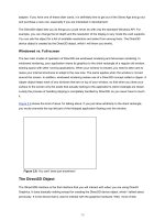
done as a preprocessing step. An example of a sphere map texture appears in Figure 10.18
.
580
Figure 10.18: A texture map for use with spherical environment mapping
The region outside of the circle in the above image is black, but it can be any color; you're never
actually going to be addressing from those coordinates, as you'll see in a moment.
Once you have the spherical texture map, the only task left to do is generate the texture coordinates for
each vertex. Here comes the trick that runs the algorithm:
The normal for each vertex, when transformed to view space, will vary along each direction from −1 to
1. What if you took just the x and y components and mapped them to (0,1)? You could use the following
equation:
You know that the radius of the 2D vector <n
x
, n
y
> will vary between 0 (when z is 1.0 and the normal is
facing directly towards the viewer) and 1 (when z is 0.0 and the normal is perpendicular to the viewer).
When n
x
and n
y
are 0, you'll get a u,v pair of <0.5, 0.5>. This is exactly what was wanted: The vertex
whose normal is pointing directly towards us should reflect the point directly behind us (the point in the
center of the sphere map). The vertices along the edges (with radius 1.0) should reflect the regions on
the edge of the sphere map. This is exactly what happens.
581
As evidenced by Figure 10.19
, this environment mapping method can have really nice looking results.
Figure 10.19: In some cases, spherical environment mapping looks great.
One caveat of this rendering method is that the sphere map must remain the same, even if the camera
moves. Because of this, it often isn't useful to reflect certain types of scenes; it's best suited for bland
scenery like starscapes.
There are some mechanisms used to attempt to interpolate correct positions for the spherical
environment map while the camera is moving, but they are far from perfect. They suffer from precision
issues; while texels in the center of the sphere map correspond to relatively small changes in normal
direction, along the edges there are big changes, and an infinite change when you reach the edge of
the circle. This causes some noticeable artifacts, as evidenced in Figure 10.20
. Again, these artifacts
only pop up if you try to find the sphere map location while the camera is moving. If you always use the
same sphere map, none of this happens.
582
Figure 10.20: Spherical environment mapping can have warping artifacts
Cubic Environment Maps
With DirectX 8.0, Microsoft added support for cubic environments to Direct3D. Cubic environment maps
have been used in high-end graphics workstations for some time, and they have a lot of advantages
over spherical environment maps.
The big advantage is cubic environment maps don't suffer from the warping artifacts that plague
spherical environment maps. You can move around an object, and it will correctly reflect the correct
portion of the scene. Also, they're much easier to make, and in fact can be made in real time (producing
accurate real-time reflections).
A cubic environment map is actually a complex Direct3D texture with six different square textures, one
facing in each direction. They are:
Map 0: +X direction (+Y up, −Z right)
Map 1: −X direction (+Y up, +Z right)
Map 2: +Y direction (−Z up, −X right)
Map 3: −Y direction (+Z up, −X right)
Map 4: +Z direction (+Y up, +X right)
Map 5: −Z direction (+Y up, +X right)
The six environment maps that are used in the images for this section appear in Figure 10.21
below.
583
Figure 10.21: The six pieces of a cubic environment map
How do you actually use this environment map to get texture coordinates for each of the vertices? The
first step is to find the reflection vector for each vertex. You can think of a particle flying out of the
camera and hitting the vertex. The surface at the vertex has a normal provided by the vertex normal,
and the particle bounces off of the vertex back off into the scene. The direction it bounces off in is the
reflection vector, and it's a function of the camera to vertex direction and vertex normal. The equation to
find the reflection vector r is:
where r is the desired reflection vector, v is the vertex location, c is the camera location, and n is the
vertex normal. The d vector is the normalized direction vector pointing from the camera to the vertex.
Given the reflection vector, finding the right texel in the cubic environment map isn't that hard. First, you
find which component of the three has the greatest magnitude (let's assume it's the x component). This
determines which environment map you want to use. So if the absolute value of the x component was
the greatest and the x component was also negative, you would want to use the −X direction cubic map
(map 1). The other two components, y and z in this example, are used to index into the map. We scale
them from the [−1,1] range to the [0,1] range. Finally you use z to choose the u value and y to choose
the v value.
Luckily Direct3D does the above so you don't have to worry about it. There are some truly icky cases
that arise, like when the three vertices of a triangle all choose coordinates out of different maps. There
is some interesting literature out on the web as to how hardware does this, but it's far too ugly to cover
here.
584
The sphere you saw being spherically environment mapped earlier appears with cubic environment
mapping in Figure 10.22
. Notice that all of the artifacts are gone and the sphere looks pretty much
perfect.
Figure 10.22: Sweet, sweet cubic environment mapping
Checking to see if a device supports cubic environment mapping is fairly simple given its device
description. Have a look at DirectX 9.0 C++ Documentation/DirectX Graphics/Using DirectX
Graphics/Techniques and Special Effects/Environment Mapping/Cubic Environment Mapping.
Once you have your cubic environment maps set up, to activate the feature all you need is to select the
texture and set up the texture processing caps to generate the reflection vector for you. Code to do this
appears in Listing 10.6
.
Listing 10.6: Activating cubic environment mapping
// pCubeTex is our cubic environment map
// pDevice is our LPDIRECT3DDEVICE9 interface pointer
// Since our texture coordinates are automatically generated,
// we don't need to include any in the vertices
DWORD dwFVF = D3DFVF_XYZ | D3DFVF_NORMAL;
pDevice->SetTextureStageState(
0,
585
D3DTSS_TEXCOORDINDEX,
D3DTSS_TCI_CAMERASPACEREFLECTIONVECTOR );
pDevice->SetTexture( 0, pCubeTex );
// Draw our object
Specular Maps
The types of lighting you can approximate with multitexture isn't limited to diffuse color. Specular
highlights can also be done using multitexture. It can do neat things that specular highlights done per-
vertex cannot, like having highlights in the middle of a polygon.
A specular map is usually an environment map like the kind used in spherical environment mapping that
approximates the reflective view of the lights in our scene from the viewpoint of an object's location.
Then you just perform normal spherical (or cubic) environment mapping to get the specular highlights.
The added advantage of doing things this way is that some special processing can be done on the
specular map to do some neat effects. For example, after creating the environment map, you could
perform a blur filter on it to make the highlights a little softer. This would approximate a slightly matte
specular surface.
Detail Maps
A problem that arises with many textures is that the camera generally is allowed to get too close to
them. Take, for example, Figure 10.23
. From a standard viewing distance (15 or 20 feet away), this
texture would look perfectly normal on an 8- to 10-foot tall wall.
586
Figure 10.23: An example wall texture
However, a free-moving camera can move anywhere it likes. If you position the camera to be only a few
inches away from the wall, you get something that looks like Figure 10.24
. With point sampling, we get
large, ugly, blocky texels. With bilinear or trilinear filtering the problem is even worse: You get a blurry
mess.
587
Figure 10.24: Getting too close to our wall texture
This problem gets really bad in things like flight simulators. The source art for the ground is designed to
be viewed from a distance of 30,000 feet above. When the plane is dipping close to the ground, it's
almost impossible to correctly gauge distance; there isn't any detail to help you gauge how far off the
ground it is, resulting in a poor visual experience.
A bad solution is to just use bigger textures. This is bad for several reasons; most of them tied to the
memory requirements that larger textures bring. You can use larger textures in the scene, but then you
need to page to system RAM more, load times are longer, etc. This entire headache, and all you get is
improved visual experience for an anomalous occurrence anyway; most of the user's time won't be
spent six inches away from a wall.
What this problem boils down to is the designed signal of an image. Most textures are designed to
encode low-frequency signals, the kind that changes over several inches. The general color and shape
of an image are examples of low-frequency signals.
The real world, however, has high-frequency signals in addition to these low-frequency signals. These
are the little details that you notice when you look closely at a surface, the kind that change over
fractions of an inch. The bumps and cracks in asphalt, the grit in granite, and the tiny grains in a piece of
wood are all good examples of high-frequency signals.
588
While you could hypothetically make all of the textures 4096 texels on a side and record all of the high-
frequency data, you don't need to. The high-frequency image data is generally really repetitive. If you
make it tile correctly, all you need to do is repeat it across the surface. It should be combined with the
base map, adding detail to it (making areas darker or lighter).
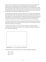
Figure 10.25
has the detail map that you'll use in the application coming up in a little bit. The histogram
of the image is tightly centered around solid gray (127,127,127). You'll see why in a moment. Also, it's
designed without lots of sharp visual distinctions across the surface, so any details quickly fade away
with MIP level increases.
Figure 10.25: The detail map used in this example
If you tile the high-frequency detail map across the low-frequency base map, you can eliminate the
blurry artifacts encountered before. As an added bonus, after you get far enough away from a surface,
the MIP level for the detail map will be solid gray so you can actually turn it off, if you'd like, for faraway
surfaces. Doing this improves the performance penalty on non-multitexture hardware since you don't
need to do an extra pass for the detail map for every polygon on the screen—only the ones that will
benefit from it. Figure 10.26
shows the base map with the detail map applied.
589
Figure 10.26: The base map combined with the detail map
There are two primary ways to implement detail maps. Actually, there are three methods, but two of
them are very closely related. Which one to use depends on the hardware configuration of the machine
running the code.
The preferred, ideal, use-this-if-it's-available way to implement detail maps is using the ADDSIGNED
blending mode. To recap, the equation for the ADDSIGNED blending mode is:
This essentially does an addition, having one of the textures have signed color values (−127 128)
instead of the unsigned values (0 255) that you're used to. Black corresponds to −127, white
corresponds to 128, and solid gray corresponds to 0. If the second texture map is a solid gray image
(like the detail map at a low MIP map level), the result of the blend is just the other texture.
The way ADDSIGNED works is that lighter-gray texels in the detail map will brighten the base map, and
darker-gray texels will darken it. This is exactly what you want. Source code to set it up using
multitexture appears in Listing 10.7
. One important difference with the light map code is you usually
define a second pair of texture coordinates that wrap over the texture map multiple times (for example,
u would vary from 0 1 in the base map, 0 8 in the detail map).
Listing 10.7: Sample code for setting up detail mapping using multitexture
//pDevice is a valid LPDIRECT3DDEVICE9 object
//pBase is the base texture
590
//pDetailMap is the detail map
pDevice->SetTextureStageState( 0, D3DTSS_COLORARG1, D3DTA_TEXTURE );
pDevice->SetTextureStageState( 0, D3DTSS_COLOROP, D3DTOP_SELECTARG1 );
// use the low-frequency texture coordinates
pDevice->SetTextureStageState( 0, D3DTSS_TEXCOORDINDEX, 0 );
pDevice->SetTexture( 0, pBase );
pDevice->SetTextureStageState( 1, D3DTSS_COLORARG1, D3DTA_TEXTURE );
pDevice->SetTextureStageState( 1, D3DTSS_COLORARG2, D3DTA_CURRENT );
pDevice->SetTextureStageState( 1, D3DTSS_COLOROP, D3DTOP_ADDSIGNED );
// use the high-frequency texture coordinates
pDevice->SetTextureStageState( 1, D3DTSS_TEXCOORDINDEX, 1 );
pDevice->SetTexture( 1, pDetailMap );
// draw polygon
If the ADDSIGNED blending mode isn't available on the hardware you're running on, don't despair;
there are other options. Well, there's actually just two, and they're almost the same. The first backup
option is to use the MODULATE2X blending mode. To recap, the equation for this blending mode is:
Looking at the equation, realize that if arg2 (the detail map) is 0.5 or solid gray, then the equation will
resolve to arg1 (the base map). Also, if arg2 is a lighter gray, arg1 will be brighter; if arg2 is darker, arg1
will be darker, just like ADDSIGNED. MODULATE2X is also supported by more hardware devices than
ADDSIGNED. To handle mod2x rendering, just use the same code in Listing 10.7
, replacing
D3DTOP_ADDSIGNED with D3DTOP_MODULATE2X. The only problem is that the MODULATE2X
blending mode tends to wash out colors a little, so it is less ideal than ADDSIGNED. It'll do the job well
enough, however, when ADDSIGNED isn't supported.
What do you do if you can't add detail maps in the same pass as our base map? What if the hardware
you're designing for only has two stages, and the second stage is already taken up by light map
rendering? You can do detail rendering multipass. All you need to do is mimic what MODULATE2X
does in multitexture with an alpha blending step.
591
Let's take the original equation above, and move pieces of it around:
You draw the scene once with the base map, and then draw it again with the detail map. The dest color
will be the base map color, and the source color will be the detail map color. All you need to do is have
the source blending factor be the destination color and the destination blending factor be the source
color. This blending operation isn't supported on all hardware; so again, you should check the device
description to make sure you can do it.
Coding up a multipass detail map renderer is fairly simple; it's very similar to the light map renderer I
discussed earlier in the chapter. Source code to set it up appears in Listing 10.8
.
Listing 10.8: Sample code for setting up detail mapping using multipass
//pDevice is a valid LPDIRECT3DDEVICE9 object
//pBase is the base texture
//pDetailMap is the detail map
pDevice->SetTextureStageState( 0, D3DTSS_COLORARG1, D3DTA_TEXTURE );
pDevice->SetTextureStageState( 0, D3DTSS_COLOROP, D3DTOP_SELECTARG1 );
// use the low-frequency texture coordinates
pDevice->SetTextureStageState( 0, D3DTSS_TEXCOORDINDEX, 0 );
pDevice->SetRenderState( D3DRENDERSTATE_ALPHABLENDENABLE, FALSE );
pDevice->SetTexture( 0, pBase );
// draw polygon
pDevice->SetRenderState( D3DRS_ALPHABLENDENABLE, TRUE );
pDevice->SetRenderState( D3DRS_SRCBLEND, D3DBLEND_DESTCOLOR );
pDevice->SetRenderState( D3DRS_DESTBLEND, D3DBLEND_SRCCOLOR );
// use the high-frequency texture coordinates
pDevice->SetTextureStageState( 0, D3DTSS_TEXCOORDINDEX, 1 );
592
pDevice->SetTexture( 0, pDetailMap );
// draw polygon
Application: Detail
To show off the texture loading code I set up earlier in the chapter and explain detail textures, I threw
together a simple application that shows the base map/detail map combo used throughout this section.
The application uses the new version of the GameLib library (which has texture support). A screen shot
from the application appears in Figure 10.27
.
Figure 10.27: Screen shot from the detail texturing application
There are two main pieces of code that are important for this application: the device checking code and
the actual code to draw the unit. The rest is essentially initialization and upkeep and won't be listed here
for brevity. See Listing 10.9
for the source code.
Listing 10.9: Device checking code for the Detail sample
bool CheckCaps()
{
D3DCAPS9 DevCaps;
Graphics()->GetDevice()->GetDeviceCaps( &DevCaps );
593
m_bCanDoMultitexture = false;
if( DevCaps.MaxSimultaneousTextures>1)
{
m_bCanDoMultitexture = true;
}
m_bCanDoAddSigned = false;
if( DevCaps.TextureOpCaps & D3DTEXOPCAPS_ADDSIGNED )
{
m_bCanDoAddSigned = true;
}
if( !(DevCaps.TextureOpCaps & D3DTEXOPCAPS_MODULATE2X) )
{
// the device can't do mod 2x. If we also can't do add signed,
// we have no way to do the multitexture.
if( !m_bCanDoAddSigned )
{
// turn off multitexture and just go with the one detail texture
m_bCanDoMultitexture = false;
}
}
bool bSrcColor = DevCaps.SrcBlendCaps & D3DPBLENDCAPS_SRCCOLOR;
bool bDestColor = DevCaps.SrcBlendCaps & D3DPBLENDCAPS_DESTCOLOR;
if( !m_bCanDoMultitexture && !(bSrcColor && bDestColor) )
{
// device couldn't do the alpha blending we wanted.
return false;
}
return true;