Enhancing CAD Drawings with Photoshop phần 7 potx
Bạn đang xem bản rút gọn của tài liệu. Xem và tải ngay bản đầy đủ của tài liệu tại đây (1.71 MB, 38 trang )
FAKING REFLECTION AND REFRACTION
213
10. Create a new layer called Intensity. Select the Magic Wand tool; click the Add To Selection but-
ton on the Options bar. Click inside each of the three windows to create a selection. Convert the
selection to a mask by clicking the Add Layer Mask button in the Layers palette. Click the
Intensity layer thumbnail to select it.
11. Select the Brush tool in the toolbox, and build up a lighting intensity by painting in grayscale.
There is really no right way to do this; feel free to make brush strokes however you see fit—the
point is to create variation on the glass surface—but here is what I did:
◆ I choose a 250-pixel soft brush and used the square bracket keys to change sizes and
hardness.
◆ I changed the foreground color to dark gray (HSB values of 0,0,25).
◆ I painted a few diagonal brush strokes across the windows.
◆ I changed the foreground color to light gray (HSB values of 0,0,75).
◆ I painted a few more brush strokes across the windows, obscuring all the blue areas (see
Figure 6.26).
At this point, you could leave the windows as they are for an abstract look. For more realism,
however, you’ll paste a photograph of the sky into the window area in step 14. Before this, you
will need to recall the window selection from the Intensity layer mask.
12. Select the Intensity layer mask thumbnail by clicking it in the Layers palette. Right-click this
mask to open the context menu shown in Figure 6.27, and select Add Layer Mask To Selection.
The marching ants appear in the window boundaries.
Figure 6.26
Painting lighting
intensity
4386.book Page 213 Monday, November 15, 2004 3:27 PM
214
CHAPTER 6 ELEVATING THE ELEVATION
Figure 6.27
Recalling a selection
from a mask
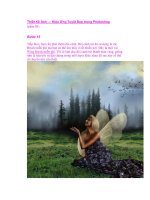
13. Open the file Sky.jpg from the companion CD. Press Ctrl+A and then Ctrl+C to select all and
copy to the Clipboard. Close Sky.jpg without saving.
14. Choose Edit Paste Into; a new layer appears with a mask in the shape of the selection. In the
Layers palette, rename this new layer Clouds. Press V to select the Move tool, and drag the
clouds around until you find an aesthetically pleasing position for them inside the window
boundaries. Change the blend mode of the Clouds layer to Soft Light, and set Opacity to 50%
to partially reveal the Intensity layer below (see Figure 6.28).
Figure 6.28
The Clouds layer gets its
own mask and settings.
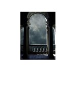
The glazing system in the entry area will also receive a photographic reflection. Instead of simply
reflecting clouds, you can reveal a bit of the building site’s context by reflecting the opposite
side of the street in the glazing.
15. Press W to select the Magic Wand. Click inside each of the remaining window boundaries,
including the glass panels in the door, to build a selection. Open the file Reflection.jpg from
the companion CD. Choose Select All, and then choose Copy (press Ctrl+A and then press
Ctrl+C), and then close Reflection.jpg. Paste the image from the Clipboard into the selection
by pressing Shift+Ctrl+V (see Figure 6.29). Rename the new layer Reflection.
The image you pasted into the glazing selection in the previous step is too small; enlarge it by
transforming the layer.
4386.book Page 214 Monday, November 15, 2004 3:27 PM
FAKING REFLECTION AND REFRACTION
215
Figure 6.29
Pasting the reflection
image into the selection
16. Press Ctrl+T to transform the Reflection layer. On the Options bar, click the Maintain Aspect
Ratio button (the icon that looks like links in a chain). Click inside the Set Horizontal Scale text
box to make it active. Press and hold the Up arrow key until the reflection image fills the glaz-
ing boundaries; the Width and Height values should reach at least 123%. Click the Commit
button.
17. You can simulate refraction by liquifying the reflection and warping the image. Be careful not
to go overboard with this tool; aim for subtle warping only: choose Filter Liquify to open the
Liquify dialog box. Click the Forward Warp tool (the top tool on the Liquify dialog box tool-
bar). Put your mouse over the image and drag a short distance; the pixels warp and flow, as
shown in Figure 6.30. Continue selecting other locations and dragging short distances to dis-
tort the straight lines between the buildings. Press Ctrl+Z if you make a mistake, and click OK
when you are satisfied with the results.
NOTE Refer to Photoshop Help for more information on the powerful (and fun) Liquify command.
Right now the glazing system looks more like a mirror because the reflection is at full intensity.
Tone down the reflectivity with a black-to-white gradient.
18. Apply a Gradient Overlay layer style effect to the Reflection layer. In the Layer Style dialog
box, set Opacity to 75% and Scale to 150%. Click OK. Figure 6.31 shows the final reflection and
refraction.
19. Save the file as Elevation4.psd. If you’re going to continue working through the following
sections, you can leave this file open for now.
4386.book Page 215 Monday, November 15, 2004 3:27 PM
216
CHAPTER 6 ELEVATING THE ELEVATION
Figure 6.30
Warping a liquid image
Figure 6.31
Reflection and refraction
complete
4386.book Page 216 Monday, November 15, 2004 3:27 PM
ADDING ENTOURAGE
217
Adding Entourage
Adding human entourage gives the viewer a sense of scale, and adding vegetation can soften the
building and provide context for the construction. You will use the entourage library developed in
Chapter 4, “You and Your Entourage,” to enhance this elevation.
It is wise to create a layer set when you anticipate creating a series of related layers; the added orga-
nization will help you navigate a crowded Layers palette.
1. If you have Elevation4.psd open from the previous exercise, you can continue here; if not,
open that file from the companion CD before continuing.
2. Create a new layer set called Entourage: click the Create A New Set button in the Layers pal-
ette, double-click Set 1, and rename it.
3. Open the file EntourageLibrary.psd from the Chapter 4 folder on the companion CD.
4. Drag the WomanFront layer into the Elevation4 document window; it appears in the Entou-
rage layer set. Minimize the EntourageLibrary.psd window for now; you will need it later in
this section.
5. Select the Move tool in the toolbox, and drag the woman’s feet to rest on the ground line. Press
Ctrl+T for transform, and then hold down Shift to lock the aspect ratio. Drag one of the upper
handles downward until the woman’s eyes align with the third reveal. Press the Commit but-
ton on the Options bar. Drag the woman in front of the door, with her toes slightly below the
ground line, as shown in Figure 6.32. Apply a Drop Shadow; in the Layer Style dialog box, set
a 13 px Distance and 9 px Size.
6. Notice that the entourage (and her shadow) extends below the building. Let’s hide this by add-
ing a shape layer that also visually grounds the building. Select the Rectangle tool in the tool-
box. On the Options bar, click the Shape Layers button and change the color swatch to medium
gray. Drag out a long thin rectangle that aligns with the bottom of the building (see Figure 6.33).
Figure 6.32
Transforming human
entourage
4386.book Page 217 Monday, November 15, 2004 3:27 PM
218
CHAPTER 6 ELEVATING THE ELEVATION
Figure 6.33
Grounding the building
with a shape layer
7. Time to add another piece of entourage from your library: the plum tree. Maximize the Entourage-
Library window. Drag the PlumTree layer into the Elevation4 window. Close EntourageLibrary
.psd. Press V to select the Move tool, drag the tree down to the top of the ground line, and cen-
ter it. Press Ctrl+T, and scale the tree down and position it as shown in Figure 6.34.
The shadows of leaves from a deciduous tree can be pleasing. To accentuate the drama of fil-
tering light through the leaves, you will treat these shadows in a special way. Start by gener-
ating shadows with an effect, and then convert the effect to a layer. You will later transform
and distort the shadow layer separately from the tree.
Figure 6.34
Adding more entourage
4386.book Page 218 Monday, November 15, 2004 3:27 PM
ADDING ENTOURAGE
219
8. Apply a Drop Shadow layer style effect to the PlumTree layer. In the Layer Style dialog box,
set a 0 px Distance and a 2 px Size to generate crisp shadows that are directly behind the tree.
9. In the Layers palette, right-click the Drop Shadow effect under the PlumTree layer to open a
context menu; select Create Layer. A warning dialog box appears, informing you that some
effects cannot be reproduced with layers; click OK to close the dialog box.
10. In the Layers palette, click the PlumTree’s Drop Shadow that was just generated in the previ-
ous step. Change the opacity of this layer to 40% to dim the shadows a bit (see Figure 6.35).
Figure 6.35
Lighten the tree’s
shadow by using the
layer Opacity setting.
11. Press Ctrl+T and then right-click in the document window. Select Distort from the context
menu. Drag the transform handles around to distort the shadow and separate them from the
tree itself, as shown in Figure 6.36. Click the Commit button on the Options bar or press Enter
when you are satisfied with the shadow form.
12. A more subtle way of illustrating entourage is to show only shadows. You might prefer this
technique if you feel that the entourage diverts too much attention from the structure. Dupli-
cate the existing tree (mirroring and distorting the new layer to make the copy seem different),
and apply a Drop Shadow effect, as I described in Chapter 4. Then remove the tree itself and
erase the shadow pixels that extend beyond the building.
Figure 6.36
Distorting the tree’s
shadow
4386.book Page 219 Monday, November 15, 2004 3:27 PM
220
CHAPTER 6 ELEVATING THE ELEVATION
13. The last items that can be attended to in this project are the sheet details. Add a title, logo, and
scale bar to the sheet, referring to Chapter 5 for instructions if necessary. Figure 6.37 shows the
final elevation image. A version of this image is provided in the color section.
14. Save your work as Elevation5.psd if you plan to refer to it again. This file is also provided on
the CD for reference.
Figure 6.37
The completed
elevation project
Summary
In this chapter you have taken a line drawing in AutoCAD and transformed it into an image that
enhances the impression a viewer receives from the design. You were exposed to numerous tips and
tricks that you can refer to when working on your own projects. The next chapter introduces you to
the art of compositing: you’ll layer images made in Autodesk VIZ and improve them dramatically
with Photoshop.
4386.book Page 220 Monday, November 15, 2004 3:27 PM
Chapter 7
Creative Compositing
You will use both Adobe Photoshop and Autodesk VIZ in the compositing techniques presented in
this chapter. In this context,
compositing
is the art of blending and enhancing images rendered in VIZ
within Photoshop.
As you may know, one of the liabilities of solely using VIZ to create computer-generated imagery
(CGI) is the huge amount of time usually required to calculate photo-realistic renderings. Compositing
is a technique that speeds up this process by leveraging the power of Photoshop. Instead of spending
time in VIZ designing realistic materials, simulating real-world light sources, and waiting for a
lengthy rendering calculation, Photoshop adds real-time realism to basic 2D imagery output from VIZ.
The compositing process begins in VIZ, where we’ll prepare a 3D model for rendering. Each object
is separately matted and rendered in VIZ with an alpha channel to preserve the object boundaries in
the images. This series of rendered images is then integrated in Photoshop into a composite whole.
In the transfer, each VIZ object becomes a layer in Photoshop, and the alpha channels become layer
masks.
To gain an understanding of how compositing works, you’ll step through a high-rise building
tutorial that shows you how to manually transfer objects from VIZ to masked layers in Photoshop.
You’ll save time processing the remaining objects in the scene by using MAXScript and an action that
automate the transfer from VIZ into Photoshop.
Once the project is assembled in Photoshop, you’ll add realism with many of the same layer style
effect techniques presented in Chapters 5 and 6, plus you’ll explore new creative compositing tech-
niques. This chapter’s topics include the following:
◆
Rendering in Autodesk VIZ
◆
Compositing in Photoshop
◆
Applying Effects to Masked Layers
◆
Working with the Environment
◆
Making Adjustments with Clipping Groups
◆
Adding to the Composite
Rendering in Autodesk VIZ
You will start the high-rise building tutorial in Autodesk VIZ 2005. A free trial version of Autodesk
VIZ 2005 is available at
www.autodesk.com
. Install Autodesk VIZ 2005 on your computer even if you
are accustomed to using other 3D software, because the techniques and automation presented in this
4386.book Page 221 Monday, November 15, 2004 3:27 PM
222
CHAPTER 7
CREATIVE COMPOSITING
chapter are specific to VIZ. After you understand the compositing process, you can adapt the proce-
dures you learn in this chapter to your favorite 3D software package (such as 3ds max, formZ, Light-
wave, Maya, and others).
TIP
The building model is provided in additional file formats (
.3ds
,
.dxf
, and
.wrl
) on the com-
panion CD for greater compatibility with other 3D programs.
Exploring the 3D Model
One of the strengths of compositing CGI in Photoshop is that you can use a basic 3D model to start
the process. You’ll save a lot of time in VIZ not having to worry about designing realistic materials,
placing physically accurate light sources, building a highly complex model, or rendering with radi-
osity or mental ray because all the realism will be added with Photoshop. You need only begin with
a simple massing model in VIZ, in a scene having the basic materials, lighting, and camera setup. It
is important to familiarize yourself with the VIZ scene because its structure determines what you will
be working on in Photoshop later in this chapter.
1.
Launch Autodesk VIZ 2005.
2.
Open the file
Building.max
from the companion CD. The Perspective viewport appears max-
imized in the VIZ interface (see Figure 7.1). Notice the various parts of the scene, including the
model, light sources, and camera.
Figure 7.1
The 3D model in VIZ
Omni lights
Camera Direct light Building 3D model Ground plane
4386.book Page 222 Monday, November 15, 2004 3:27 PM
RENDERING IN AUTODESK VIZ
223
Omni lights illuminate in all directions, and two are used for basic or ambient light in the
scene. These are set to render with a multiplier of 0.5 (each at half of normal intensity) so as not
to wash out the scene with too much illumination. Because the omnis simulate ambient light,
they are not set to cast shadows. One omni light source is below the ground plane; this acts as
a backlight to round out illumination on the building.
A direct light is positioned in relation to the building as if it were the sun in the midafternoon.
You will be using the direct light to cast shadows on the building later in this section.
NOTE
If you are interested in making a more accurate lighting simulation, use the Sunlight system
instead of a direct light in VIZ. The Sunlight system is an accurate sun-angle calculator that takes
geographic location and time into account to locate the light source.
A single camera is also provided in the scene to get you started framing your composition. The
building model itself is composed of several objects. To investigate this, look at objects by name:
3.
Open the Select Objects dialog box (press H), as shown in Figure 7.2. All the objects in the scene
are shown, including the lights and the camera. To display a listing of the geometrical objects
only, click the None button in the List Types group, and then check Geometry to display this
category in the list box.
Figure 7.2
Geometrical objects in
the scene
4.
Click the first item in the list, in this case Framing, and then click the Select button to close the
Select Objects dialog box. Right-click in the viewport, and choose Hide Unselected from the
display quad.
4386.book Page 223 Monday, November 15, 2004 3:27 PM
224
CHAPTER 7
CREATIVE COMPOSITING
5.
Navigate to get a better view of the object. Drag the wheel button to pan, turn the wheel to
zoom, and hold down the Alt key while dragging the wheel button to arc rotate. Figure 7.3
shows a better view of the Framing object. This object was initially made with the Railing tool
(which can be found in VIZ on the Create tab of the Command Panel under AEC Extended)
and later collapsed to an Editable Poly to save memory.
Figure 7.3
Framing object
6.
Right-click and choose Unhide All from the display quad. Press H and select the next object in
the Select Objects dialog box (Glass Curved). Click the Select button and right-click in the
viewport again. Choose Hide Unselected from the display quad so that you can see this object
by itself. Repeat this step over and over until you have visualized each object (there are nine
total); this is a good way to get familiar with the scene’s organization and how its objects are
named.
7.
Right-click and choose Unhide All from the display quad. Take a quick look at the materials in
the scene.
8.
Open the Material Editor dialog box (press M), as shown in Figure 7.4. Most materials are as
simple as possible, using only flat color. One material uses a Tiles map to add interest to the
masonry surface. The editor contains six materials; click each one and investigate. Close the
Material Editor dialog box when you are satisfied.
4386.book Page 224 Monday, November 15, 2004 3:27 PM
RENDERING IN AUTODESK VIZ
225
Figure 7.4
Investigating materials
Composing the Scene
Now that you are familiar with the scene, it is time to set up the camera to create a composition that
you will later render. You will need to adjust the camera angle and output size so that the composition
takes in the entire building in two-point perspective.
Before you can truly compose the scene, you have to select an output size because the composition
will relate to the image aspect ratio of the width and height values you select. You’ll then need to see
the image aspect in the viewport before you can settle on a composition.
1.
Press C to enter the Camera viewport. The point of view changes as you leave the Perspective
viewport and enter the Camera view (see Figure 7.5).
2.
Right-click the viewport name (the word
Camera
) in the upper-left corner of the viewport.
Choose Select Camera from this viewport menu (see Figure 7.6).
3.
Select the Select And Move tool (press W). Notice that the Z transform type-in at the bottom of
the user interface shows an elevation of 5~FT for the camera. Because the ground plane is at an
elevation of 0, the camera height approximates eye level on the ground for most people. To
make a realistic rendering of this building, you will be committed to rendering from this van-
tage point, rather than from a point hovering in space above the ground (as if the camera were
in a helicopter). In this way, the rendering you make will truthfully represent what a person
would see from the street.
4386.book Page 225 Monday, November 15, 2004 3:27 PM
226
CHAPTER 7
CREATIVE COMPOSITING
Figure 7.5
The initial Camera view
Figure 7.6
Accessing the
viewport menu
4.
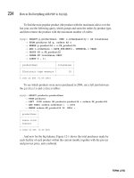
Open the Render Scene dialog box (press F10). Click the Common tab if it is not already selected.
In the Output Size group, enter 768 for Width and 1024 for Height (values in pixels). Notice
that the Image Aspect parameter reads 0.75, meaning this is the relationship you are selecting
of width to height in your output (see Figure 7.7).
5.
Right-click the viewport name and choose Show Safe Frame. The outer rectangle in Figure 7.8
displays the image aspect ratio of your chosen output size. You can disregard the inner rect-
angles as they are for live-action sequences.
Clearly there is a problem with the composition in Figure 7.8; about half the image shows the
ground. Because you want to keep the camera on the ground in a realistic viewing location,
you will need to rotate the camera upward to see the top of the building.
4386.book Page 226 Monday, November 15, 2004 3:27 PM
RENDERING IN AUTODESK VIZ
227
Figure 7.7
Render scene settings
Figure 7.8
Safe frame displayed in
viewport
6.
Press E to select the Select And Rotate tool. To accurately rotate the camera upward, do so
numerically rather than by dragging the rotate gizmo in the viewport or by using the Pan Cam-
era tool. Type
111
in the X transform type-in text box at the bottom of the user interface, and
press Enter to rotate the camera upward from its initial setting of 90 degrees.
4386.book Page 227 Monday, November 15, 2004 3:27 PM
228
CHAPTER 7
CREATIVE COMPOSITING
7.
Do a quick render (press Shift+Q). The Rendered Frame Window (RFW) appears, and in a few
seconds a rendering is processed. Figure 7.9 shows the three-point perspective rendering.
Figure 7.9
The three-point
perspective rendering
NOTE
See Chapter 1, “The Basics,” for a description of two- and three-point perspective as they
relate to tall buildings.
8.
Two-point perspective forces the building’s outer walls to appear as vertical lines: right-click
in the Camera viewport. An additional choice appears under the tools 1 quad menu. Click
Apply Camera Correction Modifier. Then click the Modify tab of the Command Panel, and
notice that a modifier is applied to the Camera object. No adjustment is required unless the
walls don’t appear vertical.
WARNING
The Apply Camera Correction Modifier is available in the quad menus only when a
camera is selected.
4386.book Page 228 Monday, November 15, 2004 3:27 PM
RENDERING IN AUTODESK VIZ
229
9.
Do another quick render (press Shift+Q). Figure 7.10 shows the two-point perspective render-
ing. This composition has an acceptable balance between ground, building, and sky; it will be
the basis of the project. A version of this image is in the color section.
10.
Save your work as
BuildingComposed.max
. You are ready to start rendering the objects in this
scene individually for later compositing in Photoshop.
Figure 7.10
Two-point perspective
rendering
Rendering Matted Objects with Alpha Channels
You can’t directly render each VIZ object separately as a 2D image and expect the pieces to fit together
in Photoshop, because objects in any 3D scene obscure one another. For example, the glass objects in
the composed rendering from the previous section are in front of, and therefore obscure portions of, the
masonry that make up the back of the building. You don’t have to worry about obscuration in 3D
because VIZ handles spatial relationships automatically.
However, you do have to think about obscuration when you render 3D geometry to pixels,
because spatial considerations are lost in Photoshop. There are two aspects to the solution of this
problem in VIZ: matte objects and alpha channels.
4386.book Page 229 Monday, November 15, 2004 3:27 PM
230
CHAPTER 7
CREATIVE COMPOSITING
Matte objects are invisible in any rendering, but they magically block geometry behind them.
Therefore, matte objects are at the root of the solution to the 3D obscuration problem in a 2D render-
ing. In VIZ, you assign matte objects by applying the Matte/Shadow material to selected objects.
NOTE
Optionally, you can set matte objects to cast and/or receive shadows, even though they are
invisible.
To preserve the boundaries of each rendered object for later compositing in Photoshop, you use
alpha channels. (See Chapter 4, “You and Your Entourage,” for more information on alpha channels.)
Alpha channels are automatically calculated in every VIZ rendering, but they can only be stored on
disk (and therefore transferred to Photoshop) in a few file formats, including
.psd
,
.tif
, and
.tga
.
We will use the Targa format (
*.tga
) in this chapter to store alpha channels. Targa images also fea-
ture optional compression for small file sizes. One peculiarity of VIZ is the requirement that the back-
ground be black to properly store anti-aliased object boundaries in the alpha channel; otherwise, a
fringe of environment color can appear around the objects.
A black environment is not a problem because we will be compositing the background image in
Photoshop, covering the black areas entirely. Let’s set the environment color and then dive into the
object-rendering work flow:
1.
In VIZ, open the Environment And Effects dialog box (press 8). Click the Environment tab if
it is not already selected (see Figure 7.11). Click the Background Color swatch to open the
Color Selector. Drag the Whiteness slider to the top to select black. Close both dialog boxes.
To render a single object, you’ll need to assign the Matte/Shadow material to all the other
objects in the scene. In this way, everything that is matted is invisible, and the object in ques-
tion is obscured appropriately, should any other objects overlap it. Once you’ve selected
everything but the object we are interested in, you can assign the Matte/Shadow material to
the selection.
2.
Choose Tools
Selection Floater to open the Selection Floater dialog box, as shown in Figure 7.12.
A floater is any dialog box that is modeless, meaning it stays open while you do other things
and until you close it. The advantage to using the Selection Floater dialog box rather than the
Select Objects dialog box (which is identical) is that the floating version stays open when you
anticipate having to keep selecting objects. Select the Framing object by double-clicking its
name. Click the Invert button at the bottom of the dialog box, and then click the Select button.
Figure 7.11
Set the black
environment.
4386.book Page 230 Monday, November 15, 2004 3:27 PM
RENDERING IN AUTODESK VIZ
231
Figure 7.12
The Selection Floater
dialog box
3.
Press M to reopen the Material Editor dialog box, as shown in Figure 7.13. Scroll to an unused
sample slot by clicking the Down arrow on the vertical scrollbar. To change the material type,
click the button that is currently marked Standard.
Figure 7.13
Changing material
types in the Material
Editor dialog box
4.
The Material/Map Browser dialog box appears (see Figure 7.14). Choose Matte/Shadow from
the list of materials and click OK.
5.
The Matte/Shadow material and its parameters appear in the Material Editor dialog box.
Uncheck Opaque Alpha in the Matte group. When this setting is unchecked, the matted objects
will not contribute to the alpha channel, so the rendering can be used for compositing. In the
Shadow group, uncheck Receive Shadows and uncheck Affect Alpha; we will deal with shad-
ows differently later in this tutorial.
4386.book Page 231 Monday, November 15, 2004 3:27 PM
232
CHAPTER 7
CREATIVE COMPOSITING
Figure 7.14
The Material/Map
Browser dialog box
6.
Click the Assign Material To Selection button on the Material Editor toolbar. Notice the white
triangular corner tabs that appear in each corner of the material sample slot; these indicate the
material is
hot
, or instanced in the scene.
7.
Do a quick render (press Shift+Q). The RFW appears, displaying the framing object in red. Click
the Display Alpha Channel button on the RFW toolbar. The grayscale alpha channel displays,
showing the boundaries of this object. Notice that the RFW indicates this is an RGB Alpha
image, meaning there are a total of four channels held in the RFW (Red, Green, Blue, and
Alpha), sometimes called RGBA.
8.
Click the Save Bitmap button on the RFW toolbar. Navigate to the folder on your hard drive
where you want to save the compositing renderings (I recommend making a folder called Out-
put); click the Save As Type drop-down list box and select Targa Image File. Type
Framing.tga
in the File Name text box and click Save.
4386.book Page 232 Monday, November 15, 2004 3:27 PM
RENDERING IN AUTODESK VIZ
233
NOTE
See Chapter 1 for a discussion of why RGBA images have 32 bits per pixel.
9.
The Targa Image Control dialog box appears. Click the 32 Bits-Per-Pixel radio button. Check
Compress for a smaller file size. Also, check Pre-Multiplied Alpha before clicking OK. Close
the RFW.
WARNING
The alpha channel must be premultiplied for efficient compositing in Photoshop;
otherwise, transparency and anti-aliasing around the object boundaries are thrown off.
Congratulations, you have successfully rendered your first compositing image! We will
repeat the object rendering process once more so you get some practice performing these
steps manually.
10.
Press Ctrl+Z to undo. This is an essential step in the object-rendering work flow! Undo doesn’t
count for the steps you performed in the RFW; in this case, it undoes the material assignment
from step 6. The objects return to their original materials, and the white triangular corner tabs
that appear in each corner of the Matte/Shadow sample slot disappear, meaning the material
is now
cold
(or unused in the scene).
11.
In the Selection Floater dialog box, click the next object (in this case, Glass Curved). Click
Invert, and then click Select.
12.
In the Material Editor dialog box, click Assign Material To Selection.
13.
Press Shift+Q to do another quick render.
14.
Click Save Bitmap in the RFW. Save the file in the same folder you used in step 8. Type
Glass
Curved.tga
in the File Name text box and click OK.
WARNING
Always use the same filename as object name to avoid confusion.
15.
Click OK in the Targa Image Control dialog box to use the same settings as you did in step 9.
16.
Close the RFW if it’s in your way, and remember to undo once and only once; press Ctrl+Z to
do this.
At this point you could repeat steps 11 through 16 for each object in the scene. Because this scene
has only nine objects, this wouldn’t take long. Feel free to do this to practice the object-rendering pro-
cess until you understand why you are performing the steps—but the next section will show you why
you don’t have to do all the work.
Automating Output with MAXScript
One of the advantages of using Autodesk VIZ is the potential to use its powerful scripting language
called MAXScript to reduce repetitive tasks. I’d like to give you a script that I’ve written to help with
the more complex scenes you may be creating in your own projects. What if there are a few hundred
objects in your 3D scene? Who would want to manually repeat the object-rendering steps that many
times? In fact, by itself this MAXScript is worth the price of this book when you consider how much
time it can save you.
4386.book Page 233 Monday, November 15, 2004 3:27 PM
234
CHAPTER 7
CREATIVE COMPOSITING
Fortunately, you don’t have to learn any MAXScript to take advantage of an automated object-
rendering pipeline; you can just run my script. However, the script provided in the Chapter 7 folder
on the companion CD is commented and easy to understand. If you have any interest in programming,
this script might be an entry point for you to explore the benefits of solving tedious tasks with code.
1.
Close the Selection Floater and/or Material Editor dialog boxes if they are still open from the
previous section.
2.
Click the Utilities tab of the Command Panel.
3.
Click the MAXScript button to display a new rollout.
4.
Click the Open Script button to open the Choose Editor File dialog box.
5.
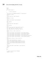
Navigate to the companion CD and open the file
RenderMatte0.4.ms
. A MAXScript window
appears with color-coded text (see Figure 7.15). A version of this image appears in the color
section.
Figure 7.15
RenderMatte
MAXScript
4386.book Page 234 Monday, November 15, 2004 3:27 PM
RENDERING IN AUTODESK VIZ
235
Read through the code and notice what is happening. The script starts by defining the user
interface. An output path is then recorded, and the Start Rendering button starts looping
through all the objects in the scene. Within the loop, an object is selected, and then the selec-
tion is inverted. Undo recording starts, and the Matte/Shadow material is assigned to the
selection. The background color is set to black, the Targa options are set, and the file is saved
as an RGBA image. An Undo restores the original materials. The next object is then processed
in exactly the same way, and so on. At the end of the loop, the user is notified that the pro-
cessing is done.
The script executes the same steps you performed manually in the last section. The great ben-
efit is that now you merely have to start the processing and you can walk away from the com-
puter while the processing takes place.
6.
To interpret the code, choose File
Evaluate All from the MAXScript window, and then
close the MAXScript window. On the Utility tab of the Command Panel, click the Utilities
drop-down list box in the MAXScript rollout and select Render Matte to display a new
rollout.
7.
You may have to scroll the panel upward to see the Render Matte rollout if your screen is set
to a low resolution. You’ll see a Render Matte rollout (see Figure 7.16) at the bottom of the Util-
ity panel; inside this rollout, click the Get Path button.
Figure 7.16
The Render Matte rollout
WARNING
Choose the output path before starting the rendering process. If you don’t, the script
will not save your renderings. Note that the renderings use the output size settings in the Render
Scene dialog box.
8.
Select a folder on your hard drive to save the renderings in the Browse For Folder dialog box
and click OK. Then click the Start Rendering button once. When the renderings are completed,
a small dialog box informs you that the processing is complete.
Figure 7.17 shows the Targa files output by the MAXScript in Windows Explorer; there will be
one file per object in the 3D scene. Be patient while the renderings are processed; there is no
progress bar to indicate how long it might take. The high-rise project should only take about
a minute (there are nine objects), but complex projects can take much longer.
4386.book Page 235 Monday, November 15, 2004 3:27 PM
236
CHAPTER 7
CREATIVE COMPOSITING
Figure 7.17
Rendered Targa files
output from MAXScript
In your own projects, do a few test renders using the procedure in the earlier “Rendering Matted
Objects with Alpha Channels” section. This will give you a sense for how long an average object takes
to render. Multiply the number of objects in your scene by your best guess for an average frame time,
and you’ll have an idea how long the entire process will take. Then use the RenderMatte MAXScript
to automate the process while you make better use of your time.
Rendering the Shadow Element
So far you have rendered only the objects themselves, but none of the shadows. Instead of rendering
shadows on each object, it is more efficient to render the shadows all together in a single image that
you can later composite in Photoshop. This way, you’ll have global control over the shadows by being
able to change the opacity of the shadow image layer.
In VIZ, you must first turn on shadow casting in at least one light source. You can then render the
shadows in a separate pass by using the Render Elements feature. Let’s see how this works:
1.
Open the Select Objects dialog box (press H). In the List Types group, click the None button to
deselect all categories. Then check Lights to display a listing of all the objects of this category.
Double-click Direct Light to select this object and close the dialog box.
2.
Click the Modify tab of the Command Panel. In the General Parameters rollout, check On in the
Shadows group. Make sure Ray Traced Shadows is selected in the drop-down list box if it’s not
already.
4386.book Page 236 Monday, November 15, 2004 3:27 PM
RENDERING IN AUTODESK VIZ
237
TIP
Ray traced shadows are the most accurate casting algorithm, and they show crisp edges.
3.
Open the Render Scene dialog box (press F10). Click the Render Elements tab. Click the Add
button and select Shadow from the list of elements (if not already present). Make sure Enable
is checked.
4.
Click the Browse button in the Selected Element Parameters group. In the Render Element
Output File dialog box, navigate to the folder in which you stored your rendered images
from the last section. The filename will automatically be
Shadow.tga (see Figure 7.18);
click OK.
5. Click the Render button at the bottom of the Render Scene dialog box. An RFW appears,
and the building progressively appears in color as the scan lines are rendered. After the
first rendering is complete, a second Shadow window appears. The shadow is completely
black in RGB. You’ll have to view the alpha channel to see the shadows against the black
background. Click the Display Alpha Channel button in the RFW toolbar, as shown in
Figure 7.19.
6. You don’t have to save the shadow rendering manually because Render Elements did that
automatically for you. Close both rendered frame windows. You are done with the 3D part
of the tutorial because all the necessary images have been rendered. Exit VIZ without saving
the scene.
Figure 7.18
Browsing a path for the
shadow rendering
4386.book Page 237 Monday, November 15, 2004 3:27 PM