Enhancing CAD Drawings with Photoshop phần 8 potx
Bạn đang xem bản rút gọn của tài liệu. Xem và tải ngay bản đầy đủ của tài liệu tại đây (1.7 MB, 38 trang )
WORKING WITH THE ENVIRONMENT
251
Figure 7.31
Dragging the
Reflection layer into
the Glazing layer set
16. Click the Reflection layer and press Ctrl+J to duplicate it. Notice that the copied layer is not
part of the clipping group, but retains the layer style effect. Rename this new layer Reflection2
and drag it between the Glass Right and Glass Curved layers.
17. Create a new clipping group. Hold down the Alt key and position your mouse on the interface
between layers Reflection2 and Glass Curved. Click when you see the clipping group cursor
appear.
18. Adjust Gradient Overlay to show the shading running vertically along the curved glass sur-
face. Double-click the f icon of the Gradient Overlay effect under the Reflection2 layer. In the
Layer Style dialog box, change the Angle to 90°, uncheck Reverse, and click OK.
19. Make another copy of the reflection and set up a new clipping group for Glass Left. Click the
Reflection2 layer and press Ctrl+J to duplicate it. Rename this Reflection3, drag it down in the
Layers palette, and drop it just above Glass Left.
20. Set up a clipping group between the Reflection3 and Glass Left layers. Figure 7.32 shows the
Glazing layer set after all the reflection clipping groups are set up.
21. Use the opacity of the various reflection layers to shade the various planes of the building dif-
ferently. Select the Reflection3 layer and change its opacity to 50%. Select the Reflection2 layer
and set its opacity to 65%.
4386.book Page 251 Monday, November 15, 2004 3:27 PM
252
CHAPTER 7 CREATIVE COMPOSITING
Figure 7.32
The Glazing layer set
with clipping groups
22. To simulate refraction and the imperfections of glass, you can optionally distort the reflection
layers. Select the Reflection layer. Choose Filter Distort Glass. The Filter Gallery dialog
box opens showing the Glass filter. Change the Distortion slider to 4 and the Smoothness to 5
(see Figure 7.33). Click OK to apply the filter.
23. Select the Reflection2 layer and press Ctrl+F to reapply the last-used filter (Glass). Select the
Reflection3 layer and press Ctrl+F again.
24. Save your work as CompositingProject3.psd. If you’re going to continue working through
the following sections, you can leave this file open for now.
Figure 7.33
Distorting the glass
4386.book Page 252 Monday, November 15, 2004 3:27 PM
MAKING ADJUSTMENTS WITH CLIPPING GROUPS
253
Making Adjustments with Clipping Groups
You might remember from Chapter 1 that you can edit adjustment layers in the layer stack (as com-
pared with adjustments). Adjustment layers are preferable because they allow you to try things out
without having to commit to them. You can change your mind later and alter the parameters of an
adjustment layer or throw it away without permanently affecting the pixels of your image.
Normally, adjustment layers affect all the layers below them in the Layers palette. That’s fine if you
want to increase the brightness of many layers at once, for example. Just add a Brightness/Contrast
adjustment layer, and it will affect everything below it in the layer stack.
On the other hand, what if you want the increased flexibility of an adjustment layer, but want to
affect only a single layer? Simple—create a clipping group with the adjustment layer and a masked
layer. Here’s how this works:
1. If you have CompositingProject3.psd open from the previous exercise, you can continue
here; if not, open that file from your hard drive before continuing.
2. Select the Masonry layer. Add a Brightness/Contrast adjustment layer by clicking Create New
Fill or Adjustment Layer at the bottom of the Layers palette. In the Brightness/Contrast dialog
box, drag the Brightness slider to +15, drag the Contrast slider to +30, and click OK.
3. Notice that the Masonry layer looks better, but the Ground and Background layers were
affected and look too bright. Hold down the Alt key and position your mouse on the interface
between the Brightness/Contrast adjustment layer and the Masonry layer. Click when you
see the clipping group cursor appear. Now the adjustment layer only affects the Masonry layer.
4. Select the Ground layer. Apply a Hue/Saturation adjustment layer. Drag the Saturation slider
to –50 and Lightness to +10. Click OK to close the Hue/Saturation dialog box.
5. Create a clipping group between the Hue/Saturation adjustment layer and the Ground layer.
6. Leave the file open for work in the next section.
4386.book Page 253 Monday, November 15, 2004 3:27 PM
254
CHAPTER 7 CREATIVE COMPOSITING
Adding to the Composite
Layer styles and adjustments are great because they maintain flexibility for you in the compositing
process. You can always go back and tweak as your composition evolves. At some milestone in
your process, you can create composite layers that contain collections of work that you have built up
from multiple layers. Because a composite layer is an aggregation of work on multiple layers, you lose
the ability to edit parameters you may have enjoyed previously.
However, the benefit of aggregating content on fewer layers is the ability to affect the composite
whole more readily (plus the simplification of the Layers palette). Let’s start cleaning up the Curtain
Wall layers by merging them in a composite layer.
1. Continue working here on the CompositingProject3.psd file from the last section.
2. Select the Curtain Wall layer set, right-click its eye icon in the Layers palette, and choose Show/
Hide All Other Layers. Now only the layers in the Curtain Wall set are visible. You can readily
see the blue glow that extends beyond the glazing system; you may remember this was origi-
nally created by the Outer Glow effect on the Framing layer.
3. Create a new layer and drag it above and out of the Curtain Wall layer set. Rename it Curtain
Wall Composite.
4. Press Alt+Shift+Ctrl+E to stamp all visible layers onto the current layer (see Figure 7.34).
Figure 7.34
The composite layer
stamped from all
visible layers
To fix the outer glow problem, you’ll need to build up a selection from all the masks of the lay-
ers in the Curtain Wall layer set. Later, you’ll create a new mask from this super-selection.
5. Right-click the layer mask thumbnail on the Framing layer. Choose Add Layer Mask To Selec-
tion from the context menu.
4386.book Page 254 Monday, November 15, 2004 3:27 PM
ADDING TO THE COMPOSITE
255
6. Repeat step 5 on each of the following layers: Glass Right, Glass Curved, and Glass Left. By
adding each of these layer masks to the selection, you are building a super-selection containing
all the masks in the layer set.
7. Select the Curtain Wall Composite layer and click the Add Layer Mask button at the bottom of
the Layers palette. The selection turns into a mask that hides the outer glow pixels.
8. Turn all the layers on. Right-click the eye icon of the Curtain Wall Composite layer, and choose
Show/Hide All Other Layers from the context menu.
9. Click the eye icon on the Curtain Wall layer set to toggle it and turn off all the layers it contains.
Next, you’ll add a lens flare to the composite layer (see Chapter 3, “Digital Darkroom Skills”).
10. Select the Curtain Wall Composite layer if it’s not already selected. Make sure its layer thumb-
nail is selected, not its layer mask thumbnail.
11. Choose Filter Render Lens Flare. In the Lens Flare dialog box, click the 50-300mm Zoom
radio button, and click a point high up on the glass in the preview area, as shown in Figure 7.35.
Click OK to close the Lens Flare dialog box when you’re finished.
12. Drag the Opacity slider down to 80% in the Curtain Wall Composite layer. The entire curtain
wall mixes a bit with the background.
TIP To further embellish the image, you could optionally add some entourage from the library
started in Chapter 3.
Now that the project is nearly complete, create a master composite layer representing all of
your work to date. This composite layer will live at the top of the Layers palette.
13. Create a new layer and drag it to the top of the Layers palette. Rename this layer Master
Composite.
Figure 7.35
Adding a lens flare to the
composite layer
4386.book Page 255 Monday, November 15, 2004 3:27 PM
256
CHAPTER 7 CREATIVE COMPOSITING
14. Press Alt+Shift+Ctrl+E to stamp all visible onto the new layer. All the other layers are irrele-
vant at this point. Still, it is best to keep the underlying layers in case future changes need to
be made to this file; this is why we avoided flattening all the layers into one.
15. Choose Filter Texture Grain. Select a low intensity in the Filter Gallery dialog box; drag the
slider to 10 and click OK.
TIP A slight amount of grain or noise helps correct problems with color banding common in inkjet
printers.
Figure 7.36 shows the final project image. A version of this image is in the color section.
Figure 7.36
The completed
compositing project
Summary
You have taken a 3D model from Autodesk VIZ and greatly enhanced its appearance in Adobe Photo-
shop though the art of compositing. Hopefully this chapter has introduced you to new avenues for
creative expression in your own work. The compositing techniques presented here offer exciting
image-based alternatives to the lengthy photo-realistic rendering process of a 3D program. In the next
chapter you’ll learn artistic options for illustrating architecture.
4386.book Page 256 Monday, November 15, 2004 3:27 PM
Chapter 8
Illustrating Architecture
For many years photo-realism has been aggressively marketed by software companies, in trade mag-
azines and in computer graphics circles. A 2004 survey at
www.cgarchitect.com
shows that the
architectural visualizations created most often, by a wide margin, are photo-realistic renderings.
Although it is certainly true that a photo-realistic 3D rendering can be spectacular and at best is
indistinguishable from a photograph, liabilities to this style are worth considering. Every facet of a
photo-realistic rendering must be specified, including 3D geometric detail, materials that correctly
simulate real-world optics, texture map coordinates, photometric luminaires, and so on. As simula-
tions of reality, photo-realistic imagery can be so accurate that nothing is left to the imagination.
But it can actually be troublesome to show clients imagery in the early design development stages
that is too realistic or pinned down, especially when the intent is to share a common vision and dia-
logue, not to debate the index of refraction of the glazing, for example.
Non–photo-realistic (NPR) illustrations convey a visual feel for a space when something softer and
less determined is called for. NPR illustration stimulates the imagination and draws attention to the
essential design ideas of your composition without attempting to be an accurate reality simulation.
This chapter is about illustrating architecture with NPR techniques that encompass both VIZ and
Photoshop. You will start in Autodesk VIZ with a 3D model and render special channels (ObjectID,
Normal, and Zdepth) that are useful in maintaining three-dimensionality and object-selectability in
a rendered 2D image. Where appropriate, you’ll also use some of the compositing skills presented in
Chapter 7 to render and convert specific objects and shadows in VIZ to masked layers in Photoshop.
You’ll improve your illustration skills in the following areas:
◆
Illustrating a 3D Model
◆
Integrating and Painting in Photoshop
◆
Working in Black and White
◆
Reproducing Grayscale Images with Colored Inks
Illustrating a 3D Model
Start the illustration project in Autodesk VIZ 2005. As mentioned in Chapter 7, a free trial version of
Autodesk VIZ 2005 is available at
www.autodesk.com
. The techniques and automation presented in
this chapter are specific to VIZ, and I recommend you use the program or its trial version to walk
through these exercises even if you are accustomed to using other 3D software. After you understand
this illustration process, you can adapt the procedures to your favorite 3D software package (such as
3ds max, formZ, Lightwave, Maya, and others).
4386.book Page 257 Monday, November 15, 2004 3:27 PM
258
CHAPTER 8
ILLUSTRATING ARCHITECTURE
TIP
The model used in this chapter is provided in additional file formats (
.3ds
,
.dxf
, and
.wrl
) on
the companion CD for greater compatibility with other 3D programs.
Rendering in VIZ
You’ll be making several renderings of the 3D model in VIZ to ultimately integrate into the illustra-
tion project for work in Photoshop. All the renderings made in this chapter will be generated from
exactly the same point of view, although each will contain different forms of image data.
Although the rendering process presented here has some similarities to the compositing process
presented in Chapter 7, there are important differences. Instead of rendering each object as a separate
image, you’ll render special image channels that allow you to select, mask, and illustrate specific sur-
faces in Photoshop.
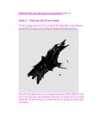
The first step when opening the sample file is to examine it and get a sense of the massing and spa-
tial qualities of the design. The 3D model I’ll use here is inspired by William Wurster’s Gregory Farm-
house design in Santa Cruz, California (1926). It is a simple residential design centered on an open
courtyard featuring spatial sophistication.
Once you visualize the 3D model, render an overall shot of the structures and tree, including an
alpha channel, to delineate all the object boundaries at once. Make a similar rendering without the
tree so that the building is easier to illustrate. To later composite the tree on top of the building, you
need to render the tree separately as a matted object. The shadows will also be rendered as a separate
element for compositing.
1.
Launch Autodesk VIZ 2005.
2.
Open the file
Farmhouse.max
from the Chapter 8 folder on the companion CD. Figure 8.1
shows the 3D model from a bird’s-eye perspective. Notice the camera at eye level on the
ground. Use the navigation tools in VIZ to get a feel for the model.
Figure 8.1
The 3D model
4386.book Page 258 Monday, November 15, 2004 3:27 PM
ILLUSTRATING A 3D MODEL
259
TIP
When exploring any 3D model for the first time, examine its objects, modifiers, materials,
lights, and so on. You can learn a lot by noticing how other artists structure their scenes.
3.
Press C to enter the Camera viewport.
4.
Right-click the viewport label (the word
Camera
) in the upper-left corner of the viewport.
Choose Show Safe Frame from the Viewport menu. This feature displays concentric rectangles
in the viewport. The outermost rectangle reveals the aspect ratio and cropped edge of the com-
position (see Figure 8.2). This is the point of view you’ll be using in the illustration project. A
version of this image is in the color section.
5.
Press F10 to open the Render Scene dialog box (see Figure 8.3). Notice the Output Size is
already set to 1024
×
768; the Width and Height parameters here control the output size for the
entire illustration project.
6.
Click the Render button to open the Rendered Frame Window (RFW). The image progressively
renders as the scan lines are processed; this should only take a few seconds (see Figure 8.4).
NOTE
The scene uses a black environment background color to ensure that object boundaries are
properly anti-aliased in the alpha channels of composited images.
Notice that the RFW shows RGB Alpha in its drop-down list box, indicating that VIZ automat-
ically renders the standard color channels plus an alpha channel that stores the object bound-
aries in a grayscale channel (see Chapter 7, “Creative Compositing”).
Figure 8.2
The camera view
4386.book Page 259 Monday, November 15, 2004 3:27 PM
260
CHAPTER 8
ILLUSTRATING ARCHITECTURE
Figure 8.3
The Render Scene
dialog box
Figure 8.4
The Rendered Frame
Window
7.
Click the Save Bitmap button in the RFW. Navigate to a project folder on your hard drive and
select Targa Image File from the Save As Type drop-down list box in the Browse Images For
Output dialog box. Type in the filename
FarmhouseandTree.tga
and click the Save button to
open the Targa Image Control dialog box (see Figure 8.5). If they are not already selected, click
the 32 Bits-Per-Pixel radio button, check Compress, and check Pre-Multiplied Alpha. Click OK
to save the file.
4386.book Page 260 Monday, November 15, 2004 3:27 PM
ILLUSTRATING A 3D MODEL
261
Figure 8.5
The Targa Image Control
dialog box
The oak tree that the courtyard is built around gets in the way of illustrating the background
structure in Photoshop. The tree’s many leaves and complex form make it difficult to mask with-
out rendering it as a separate object. Let’s turn off the tree for now and make another rendering.
8.
Click the tree to select it; the leaves appear because the AEC Foliage object is set to stay in View-
port Canopy mode only when the object is unselected in order to save memory.
9.
Right-click in the viewport to open the quad menus. Select Hide Selection from the display
quad; the tree disappears.
10.
Press Shift+Q to quickly render the scene again. The RFW appears; save the rendering as
Farmhouse.tga
with the same Targa options used previously.
The next step is to render the tree matted against all the other objects in the scene, as you did
in Chapter 7. Use the Matte/Shadow material on everything but the tree.
11.
Press M to open the Material Editor, and then press Ctrl+A to select all the objects. Click the Assign
Material To Selection button in the Material Editor (see Figure 8.6). Since the Matte/Shadow
material is the current material, it is assigned to the objects in the scene. In the Matte/Shadow Basic
Parameters rollout, make sure that Opaque Alpha, Receive Shadows, and Affect Alpha are
unchecked.
4386.book Page 261 Monday, November 15, 2004 3:27 PM
262
CHAPTER 8
ILLUSTRATING ARCHITECTURE
Figure 8.6
Assigning Matte/Shadow
material
12.
Click the Display tab of the Command Panel. Click the Unhide All button in the Hide rollout
to again display the tree.
13.
Press Shift+Q or click the Quick Render button on the main toolbar to generate another ren-
dering. In the RFW save the image as
Tree.tga
, accepting the Targa options that save a pre-
multiplied alpha channel. Close the RFW and Material Editor if they are open.
14.
Press Ctrl+Z to undo until the original materials reappear on the objects in the viewport. Click
the Unhide All button again.
15.
Press H to open the Select Objects dialog box to turn on shadow casting in the sun before ren-
dering the shadow element. Click Sun01 under Compass01 (part of the Sunlight system) and
then click Select. Click the Modify tab of the Command Panel and check On in the Shadows
group of the General Parameters rollout. Make sure that Area Shadows is selected in the drop-
down list box.
4386.book Page 262 Monday, November 15, 2004 3:27 PM
ILLUSTRATING A 3D MODEL
263
NOTE
Area shadows are softer the further they are from the casting edge.
16.
Press F10 to open the Render Scene dialog box if it is not already open. Click the Render Ele-
ments tab and open the rollout if necessary. Click the Add button and select Shadow from the
Render Elements dialog box. Then click OK.
17.
In the Render Scene dialog box, click the Browse button in the Selected Element Parameters
group to open the Render Element Output File dialog box. Type the filename
Shadow.tga
and
click Save. Click OK in the Targa Image Control dialog box. Figure 8.7 shows the resulting
Render Scene dialog box.
Render elements are post-processing effects that appear after the entire color image is rendered.
Choose not to show the RFW because you are only interested in the shadows right now.
18.
Click the Common tab in the Render Scene dialog box. Scroll down if necessary and clear Ren-
dered Frame Window in the Render Output group because you don’t need to see the color
rendering.
19.
Click the Render button. Be patient as the rendering proceeds. (It should take a few minutes.)
When the processing is complete, a Shadow RFW window appears that is all black (black shad-
ows against a black environment background color). Click the Display Alpha Channel button
to see the shadow mask (see Figure 8.8).
20.
Close the Shadow RFW, but keep the file open in VIZ.
Figure 8.7
The Render Elements
tab in the Render Scene
dialog box
4386.book Page 263 Monday, November 15, 2004 3:27 PM
264
CHAPTER 8
ILLUSTRATING ARCHITECTURE
Figure 8.8
Rendering the Shadow
element
Rendering Special Image Channels with MAXScripts
3D programs generate what I’m calling special image channels internally during the process of cal-
culating a rendering. ObjectID, Normal, and Zdepth are examples of special image channels in VIZ;
these will later aid in maintaining pseudo–three-dimensionality and object-selectability in Photo-
shop. You will eventually render these channels as image files and then composite them as channels
in the illustration project.
These channels represent data that separates the objects (ObjectID), determines which way all the
geometrical surfaces in the model are oriented (Normal), and calculates the distance each object is
from the picture plane (Zdepth).
NOTE
The Zdepth channel can alternatively be rendered as a render element.
VIZ’s graphics buffer (G-Buffer) stores object numbers that identify nodes to be included in postpro-
cessing effects. In other words, ObjectIDs are just a means to mark certain objects for postprocessing.
Accessing special image channels is an advanced topic in VIZ, so I’ve written a pair of MAXScripts
that automate this process for you. We will assign unique ObjectIDs to every object in the scene with
a MAXScript called ObjectIDAssigner. Then every object will be included on the ObjectID image
channel when we render the scene using a second MAXScript called ChannelRenderer (along with
other channels). Let’s give it a whirl. So that you are aware of what the first MAXScript is automating,
let’s first take a look at object channels as they are stored in the G-Buffer.
1.
Click the Tree object in the viewport. Right-click and choose Properties from the transform quad.
4386.book Page 264 Monday, November 15, 2004 3:27 PM
ILLUSTRATING A 3D MODEL
265
2.
On the General tab of the Object Properties dialog box (see Figure 8.9), notice that the Object
Channel (also known as the ObjectID) is set to 0. You would have to set this to a nonzero value
to include this object in the G-Buffer. Don’t change anything yet, however; click Cancel.
Figure 8.9
The Object Properties
G-Buffer Object Channel
To differentiate the objects in the G-Buffer, you would have to give each and every object in the
scene a unique ObjectID, a tedious process. Instead, use the ObjectIDAssigner MAXScript; it
assigns sequential ObjectIDs to each object automatically.
3.
Click the Utilities tab of the Command Panel. Click the MAXScript button in the Utilities rollout.
4.
Click the Open Script button, and then select the file
ObjectIDAssigner0.2.ms
from the com-
panion CD to open a MAXScript window showing the code (see Figure 8.10). Within this
window, choose File
Evaluate All. Then close the window.
Now that the code has been evaluated, it is part of VIZ. Run the utility.
5.
In the MAXScript rollout, select ObjectID Assigner from the Utilities drop-down list box.
6.
Click the Assign button once; that’s it.
4386.book Page 265 Monday, November 15, 2004 3:27 PM
266
CHAPTER 8
ILLUSTRATING ARCHITECTURE
Figure 8.10
The ObjectIDAssigner
MAXScript window
7.
To verify that objects have unique ObjectIDs, choose an object at random and check its prop-
erties: Click the roof object in the viewport. Right-click and choose Properties. Verify that the
object has a nonzero Object Channel number. Click Cancel.
8.
Now use the second MAXScript to render the special image channels discussed earlier: Click
the Open Script button in the MAXScript rollout and select the file
ChannelRenderer0.3.ms
from the companion CD. Figure 8.11 shows the MAXScript window. Even if you don’t under-
stand the language, scan the code to get a sense of what this script is doing; you will probably
understand more than you might suppose. Choose File
Evaluate All from the MAXScript
window. Then close the window.
ChannelRenderer saves the ObjectID, Normal, and Zdepth image channels as Portable Net-
work Graphics files (called ping, or
.png
, files) when it is applied as a render effect.
9.
Choose Rendering
Effects. Click the Add button, select ChannelRenderer from the list, and
click OK.
10.
Click the Get Path button (see Figure 8.12) in the Channel Renderer rollout at the bottom of the
Environment And Effects dialog box. Select the project folder on your hard drive where you’d
like to save the three
.png
images.
11.
Click the Render button in the Render Scene dialog box and wait until the rendering is com-
plete. Close all the open dialog boxes. Close VIZ without saving the file.
4386.book Page 266 Monday, November 15, 2004 3:27 PM
ILLUSTRATING A 3D MODEL
267
Figure 8.11
The ChannelRenderer
MAXScript window
Figure 8.12
Choosing where to save
the rendered images
4386.book Page 267 Monday, November 15, 2004 3:27 PM
268
CHAPTER 8
ILLUSTRATING ARCHITECTURE
Now you have rendered the special channels and elements needed for masking in preparation for
painting. Just as with house painting, most of the effort goes into the prep work. You’ll integrate these
files into Photoshop and use them to mask off areas that you’ll eventually paint.
Figure 8.13 shows all the rendered files you have made for this project in VIZ. Once you’ve com-
pleted these steps, you should have the following files:
Figure 8.13
Rendered files
Integrating and Painting in Photoshop
When painting a house, most of the work goes into preparing the building’s surfaces to receive paint
and masking off the rest of the surfaces you want to protect. Digitally illustrating a 3D model is much
the same. Before you can paint, you’ll need to integrate the various files generated in VIZ into a single
Photoshop document. You’ll then create new layers, mask them off, and organize them before you
apply digital paint with a brush.
Integrating the Renderings
You generated multiple images in VIZ showing different aspects of the 3D model, rendered from the
same point of view. How you integrate these depends on how you will use them in Photoshop to cre-
ate the illustration: in some cases, you will composite the renderings as masked layers, and in others
you will save them as channels.
Filename Description
Normal.png
Represents all the surfaces in the model in different gray tones
regardless of material or object membership
ObjectID.png
Reveals each object in rendering as a distinct grayscale value
Zdepth.png
Represents 3D space in grayscale, with objects in the fore-
ground fading from white to black as they recede from the
picture plane
Farmhouse.tga
Four-channel (RGB plus alpha) render of all buildings
(without tree)
FarmhouseandTree.tga
Four-channel (RGB plus alpha) render of all buildings plus tree
Shadow.tga
Render of shadows only
Tree.tga
Render of tree matted against all other objects
4386.book Page 268 Monday, November 15, 2004 3:27 PM
INTEGRATING AND PAINTING IN PHOTOSHOP
269
Compositing Masked Layers
You can composite the Farmhouse, Tree, and Shadow renderings the way you learned in the last
chapter; with layer masks coming from their alpha channels. In addition, you will paste a photograph
of a cloudy sky into the background.
1.
Launch Photoshop if it is not already open. Open the file
Farmhouse.tga
from your hard
drive. All the renderings are also provided in the VIZ Output subfolder within the Chapter 8
folder on the companion CD in case you are jumping in here.
2.
Choose File
Save As and change the Format drop-down list box to Photoshop in the Save As
dialog box. Save the file as
Farmhouse.psd
in the project folder on your hard drive. Make sure
Alpha Channels is checked in the Save Options group and then click Save. This file will be your
working illustration project document into which you’ll integrate other images.
TIP
You can use the Convert Alpha To Layer Mask action recorded in Chapter 7 in place of steps 3
through 6. If you assigned the F12 function key to the action then, you can now use that shortcut to
execute the action.
3.
Select the Channels palette. Click the Alpha 1 channel.
4.
Click the Load Channel As Selection button at the bottom of the Channels palette to display the
marching ants. Click the RGB channel.
5.
Select the Layers palette. Hold down the Alt key and double-click the Background layer to con-
vert it to a normal layer called Layer 0.
6.
Click the Add Layer Mask button at the bottom of the Layers palette. The selection is converted
into a layer mask, and the sky turns transparent in the document window (see Figure 8.14).
Figure 8.14
Masking the farmhouse
with its alpha channel
4386.book Page 269 Monday, November 15, 2004 3:27 PM
270
CHAPTER 8
ILLUSTRATING ARCHITECTURE
7.
Rename Layer 0 to the name of the file (Farmhouse in this case). Click the Layer thumbnail to
select it and deselect the layer mask. This layer is ready to be integrated into your illustration
project.
Open the rendering of the isolated tree, and convert its alpha channel into a layer mask before
integrating it into the Photoshop document.
8.
Open
Tree.tga and repeat steps 3 through 7, renaming the resulting layer to Tree.
9. Drag the Tree layer from Tree.tga into Farmhouse.psd. Then use the Move tool (shortcut key V)
to drag the Tree layer until it snaps into position both horizontally and vertically.
10. Open Shadow.tga and repeat steps 3 through 7, renaming the resulting layer to Shadow.
11. Drag the Shadow layer from Shadow.tga into Farmhouse.psd. Then use the Move tool (short-
cut key V) to drag the Shadow layer until it snaps into position both horizontally and vertically
(see Figure 8.15).
Paste a photograph of a cloudy sky behind the other layers and transform it to fit the composition.
12. Close Shadow.tga and then open Clouds.jpg from your hard drive.
13. Press Ctrl+A and then Ctrl+C to select all the pixels and copy them to the Clipboard. Close
Clouds.jpg.
14. Create a new layer and rename it Sky. Drag this layer to the bottom of the Layers palette. Press
Ctrl+V to paste the contents of the Clipboard onto the Sky layer.
15. Press Ctrl+T to activate the Free Transform command. On the Options bar, click the Maintain
Aspect Ratio button and then click inside the Width text box. Set Width to 77% (press and hold
the Down arrow key, or type 77 and press Enter). Notice that Height also reads 77% because
you maintained the aspect ratio. Click the Commit button.
16. Press V to select the Move tool. Drag the Sky layer and center it from right to left. Then drag
it up so the lower edge of the clouds are just below the buildings, as shown in Figure 8.16. Make
sure not to reveal the edge of the background in the final composition.
4386.book Page 270 Monday, November 15, 2004 3:27 PM
INTEGRATING AND PAINTING IN PHOTOSHOP
271
Figure 8.15
Compositing Farm-
house, Tree, and Shadow
layers
Figure 8.16
Transforming the photo-
graphic background
4386.book Page 271 Monday, November 15, 2004 3:27 PM
272
CHAPTER 8 ILLUSTRATING ARCHITECTURE
Pasting Images into Channels
In contrast to compositing masked layers, the renderings containing special image channels from VIZ
will be literally integrated as channels in Photoshop. These special channels are not meant to be com-
posited directly as layers in the final illustration, but will act as aids during the illustration process
that you will repeatedly refer to. Let’s get started integrating the images as channels in Photoshop.
1. Open the file ObjectID.png from your hard drive (see Figure 8.17). This image reveals each
object in the rendering as a distinct grayscale value. It may be hard to tell objects apart when
their grayscale values are similar, but later you will be able to select these object areas sepa-
rately using the Magic Wand.
Figure 8.17
The ObjectID channel
2. Press Ctrl+A and then Ctrl+C to copy all the ObjectID pixels to the Clipboard. Close
ObjectID.png.
3. Select Farmhouse.psd and click the Channels palette.
4. Click the Create A New Channel button at the bottom of the Channels palette and then press
Ctrl+V to paste the pixels from the Clipboard onto the new channel.
5. Rename the Alpha 2 channel ObjectID. Hereafter you’ll be able to select this channel by press-
ing Ctrl+5 without having to select the Channels palette.
4386.book Page 272 Monday, November 15, 2004 3:27 PM
INTEGRATING AND PAINTING IN PHOTOSHOP
273
6. Open the file Normal.png from your hard drive (see Figure 8.18). This image represents all the
surfaces in the model in different gray tones, regardless of material or object membership. You
will use this channel to help create selections for masking in the next section.
7. Press Ctrl+A and then Ctrl+C to copy all the Normal pixels to the Clipboard. Close
Normal.png.
8. Select Farmhouse.psd, click the Create A New Channel button at the bottom of the Channels
palette, and then press Ctrl+V to paste the pixels from the Clipboard onto the new channel.
Figure 8.18
The Normal channel
9. Rename the Alpha 2 channel Normal. Hereafter you’ll be able to select this channel by pressing
Ctrl+6 without having to select the Channels palette.
10. Open the file Zdepth.png from your hard drive (see Figure 8.19). This image represents 3D
space in grayscale, with objects in the foreground fading from white to black as they recede
from the picture plane. You will use this channel later in this chapter to create a fog or a
shadow that accentuates the spatial quality of the illustration.
NOTE The Z in Zdepth refers not to the spatial world Z axis (which is up), but to the axis that runs
along the camera-target vector, away from the picture plane.
11. Press Ctrl+A and then Ctrl+C to copy all the Zdepth pixels to the Clipboard. Close
Zdepth.png.
12. Select Farmhouse.psd, click the Create A New Channel button at the bottom of the Channels
palette, and then press Ctrl+V to paste the pixels from the Clipboard onto the new channel.
4386.book Page 273 Monday, November 15, 2004 3:27 PM
274
CHAPTER 8 ILLUSTRATING ARCHITECTURE
Figure 8.19
The Zdepth channel
13. Rename the Alpha 2 channel Zdepth. Hereafter you’ll be able to select this channel by pressing
Ctrl+7 without having to select the Channels palette.
14. Press Ctrl+D to deselect. Then press Ctrl+~ to select the RGB channels (see Figure 8.20).
15. Click the Layers palette. Note that no new layers have been created while you have been add-
ing data to the Channels palette. Press Ctrl+S to save your work. If you’re going to continue
working through the following sections, you can leave this file open for now.
Figure 8.20
The Channels Palette
You’ll be using both the ObjectID and Normal channels to make selections that will be converted
to painting masks. The alpha channel provides the outline of all the structures, so it is always useful
for masking a background image. You can optionally use the Zdepth channel to create a 3D fog that
gets thicker in the distance.
4386.book Page 274 Monday, November 15, 2004 3:27 PM
INTEGRATING AND PAINTING IN PHOTOSHOP
275
Masking and Painting Surfaces
Now that all the renderings from VIZ have been integrated into a working Photoshop document, you
are ready to start masking and painting. This tutorial must follow a particular sequence of steps to be
useful. However, I encourage you to experiment and play as you illustrate; make up your own steps
once you get a feel for it. Don’t be afraid to throw layers away and try different combinations of
masks, colors, brushes, and brush strokes to get what you are looking for.
Masking with Channels
In the following steps, we’ll use the special channels pasted into the document in the previous section
to make selections. Often the ObjectID and Normal channels are both used to select a particular sur-
face that you’d like to protect with a mask. The selection is then converted to a masked layer, ready
to receive paint. You’ll mask a couple of layers manually before saving an action that automates some
of the prep work to save time.
1. If you have Farmhouse.psd open from the previous exercise, you can continue here; if not,
open it from your hard drive before continuing. This file is also provided on the companion CD
if you are jumping in here.
2. Click the Layers palette if it is not already selected. Toggle the Shadow and Tree layers off by
clicking their eye icons. Select the Farmhouse layer. Create a layer set by clicking the Create A
New Set button at the bottom of the Layers palette, and rename the new set to Walls.
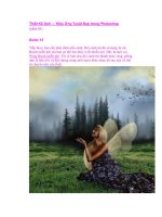
Select one of the wall surfaces in the tower using the Normal channel.
3. Click the Channels palette. Select the Normal channel or press Ctrl+6. Press W to select the
Magic Wand tool. On the Options bar, click the New Selection Mode button, type 20 into the
Tolerance text box, and check Anti-aliased and Contiguous. Clear the Use All Layers option.
4. Click a point inside the tower wall, as shown in Figure 8.21. The marching ants appear on the
selected wall surface.
Notice that part of the window is selected. We can subtract these areas from the selection using
the information contained in the ObjectID channel.
5. Press Ctrl+5 to select the ObjectID channel. Click the Subtract From Selection button on the
Options bar.
6. Click inside the window and shutter area that is within the current selection. You’ll have to
click three times to remove each shutter and the glass from the selection (see Figure 8.22).
4386.book Page 275 Monday, November 15, 2004 3:27 PM