LINUX DEVICE DRIVERS 3rd edition phần 6 pps
Bạn đang xem bản rút gọn của tài liệu. Xem và tải ngay bản đầy đủ của tài liệu tại đây (1 MB, 64 trang )
This is the Title of the Book, eMatter Edition
Copyright © 2005 O’Reilly & Associates, Inc. All rights reserved.
302
Chapter 12
CHAPTER 12
PCI Drivers
While Chapter 9 introduced the lowest levels of hardware control, this chapter pro-
vides an overview of the higher-level bus architectures. A bus is made up of both an
electrical interface and a programming interface. In this chapter, we deal with the
programming interface.
This chapter covers a number of bus architectures. However, the primary focus is on
the kernel functions that access Peripheral Component Interconnect (PCI) peripher-
als, because these days the PCI bus is the most commonly used peripheral bus on
desktops and bigger computers. The bus is the one that is best supported by the ker-
nel. ISA is still common for electronic hobbyists and is described later, although it is
pretty much a bare-metal kind of bus, and there isn’t much to say in addition to
what is covered in Chapters 9 and 10.
The PCI Interface
Although many computer users think of PCI as a way of laying out electrical wires, it
is actually a complete set of specifications defining how different parts of a computer
should interact.
The PCI specification covers most issues related to computer interfaces. We are not
going to cover it all here; in this section, we are mainly concerned with how a PCI
driver can find its hardware and gain access to it. The probing techniques discussed
in the sections “Module Parameters” in Chapter 2 and “Autodetecting the IRQ
Number” in Chapter 10 can be used with PCI devices, but the specification offers an
alternative that is preferable to probing.
The PCI architecture was designed as a replacement for the ISA standard, with three
main goals: to get better performance when transferring data between the computer
and its peripherals, to be as platform independent as possible, and to simplify add-
ing and removing peripherals to the system.
,ch12.1659 Page 302 Friday, January 21, 2005 3:08 PM
This is the Title of the Book, eMatter Edition
Copyright © 2005 O’Reilly & Associates, Inc. All rights reserved.
The PCI Interface
|
303
The PCI bus achieves better performance by using a higher clock rate than ISA; its
clock runs at 25 or 33 MHz (its actual rate being a factor of the system clock), and
66-MHz and even 133-MHz implementations have recently been deployed as well.
Moreover, it is equipped with a 32-bit data bus, and a 64-bit extension has been
included in the specification. Platform independence is often a goal in the design of a
computer bus, and it’s an especially important feature of PCI, because the PC world
has always been dominated by processor-specific interface standards. PCI is cur-
rently used extensively on IA-32, Alpha, PowerPC, SPARC64, and IA-64 systems,
and some other platforms as well.
What is most relevant to the driver writer, however, is PCI’s support for autodetec-
tion of interface boards. PCI devices are jumperless (unlike most older peripherals)
and are automatically configured at boot time. Then, the device driver must be able
to access configuration information in the device in order to complete initialization.
This happens without the need to perform any probing.
PCI Addressing
Each PCI peripheral is identified by a bus number, a device number, and a function
number. The PCI specification permits a single system to host up to 256 buses, but
because 256 buses are not sufficient for many large systems, Linux now supports PCI
domains. Each PCI domain can host up to 256 buses. Each bus hosts up to 32
devices, and each device can be a multifunction board (such as an audio device with
an accompanying CD-ROM drive) with a maximum of eight functions. Therefore,
each function can be identified at hardware level by a 16-bit address, or key. Device
drivers written for Linux, though, don’t need to deal with those binary addresses,
because they use a specific data structure, called
pci_dev, to act on the devices.
Most recent workstations feature at least two PCI buses. Plugging more than one bus
in a single system is accomplished by means of bridges, special-purpose PCI peripher-
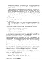
als whose task is joining two buses. The overall layout of a PCI system is a tree where
each bus is connected to an upper-layer bus, up to bus 0 at the root of the tree. The
CardBus PC-card system is also connected to the PCI system via bridges. A typical
PCI system is represented in Figure 12-1, where the various bridges are highlighted.
The 16-bit hardware addresses associated with PCI peripherals, although mostly hid-
den in the
struct pci_dev object, are still visible occasionally, especially when lists of
devices are being used. One such situation is the output of lspci (part of the pciutils
package, available with most distributions) and the layout of information in /proc/pci
and /proc/bus/pci. The sysfs representation of PCI devices also shows this addressing
scheme, with the addition of the PCI domain information.
*
When the hardware
address is displayed, it can be shown as two values (an 8-bit bus number and an 8-bit
* Some architectures also display the PCI domain information in the /proc/pci and /proc/bus/pci files.
,ch12.1659 Page 303 Friday, January 21, 2005 3:08 PM
This is the Title of the Book, eMatter Edition
Copyright © 2005 O’Reilly & Associates, Inc. All rights reserved.
304
|
Chapter 12: PCI Drivers
device and function number), as three values (bus, device, and function), or as four
values (domain, bus, device, and function); all the values are usually displayed in
hexadecimal.
For example, /proc/bus/pci/devices uses a single 16-bit field (to ease parsing and sort-
ing), while /proc/bus/
busnumber splits the address into three fields. The following
shows how those addresses appear, showing only the beginning of the output lines:
$ lspci | cut -d: -f1-3
0000:00:00.0 Host bridge
0000:00:00.1 RAM memory
0000:00:00.2 RAM memory
0000:00:02.0 USB Controller
0000:00:04.0 Multimedia audio controller
0000:00:06.0 Bridge
0000:00:07.0 ISA bridge
0000:00:09.0 USB Controller
0000:00:09.1 USB Controller
0000:00:09.2 USB Controller
0000:00:0c.0 CardBus bridge
0000:00:0f.0 IDE interface
0000:00:10.0 Ethernet controller
0000:00:12.0 Network controller
0000:00:13.0 FireWire (IEEE 1394)
0000:00:14.0 VGA compatible controller
$ cat /proc/bus/pci/devices | cut -f1
0000
0001
0002
0010
0020
0030
Figure 12-1. Layout of a typical PCI system
PCI Bus 0 PCI Bus 1
Host Bridge PCI Bridge
ISA Bridge
CardBus Bridge
RAM CPU
,ch12.1659 Page 304 Friday, January 21, 2005 3:08 PM
This is the Title of the Book, eMatter Edition
Copyright © 2005 O’Reilly & Associates, Inc. All rights reserved.
The PCI Interface
|
305
0038
0048
0049
004a
0060
0078
0080
0090
0098
00a0
$ tree /sys/bus/pci/devices/
/sys/bus/pci/devices/
| 0000:00:00.0 -> / / /devices/pci0000:00/0000:00:00.0
| 0000:00:00.1 -> / / /devices/pci0000:00/0000:00:00.1
| 0000:00:00.2 -> / / /devices/pci0000:00/0000:00:00.2
| 0000:00:02.0 -> / / /devices/pci0000:00/0000:00:02.0
| 0000:00:04.0 -> / / /devices/pci0000:00/0000:00:04.0
| 0000:00:06.0 -> / / /devices/pci0000:00/0000:00:06.0
| 0000:00:07.0 -> / / /devices/pci0000:00/0000:00:07.0
| 0000:00:09.0 -> / / /devices/pci0000:00/0000:00:09.0
| 0000:00:09.1 -> / / /devices/pci0000:00/0000:00:09.1
| 0000:00:09.2 -> / / /devices/pci0000:00/0000:00:09.2
| 0000:00:0c.0 -> / / /devices/pci0000:00/0000:00:0c.0
| 0000:00:0f.0 -> / / /devices/pci0000:00/0000:00:0f.0
| 0000:00:10.0 -> / / /devices/pci0000:00/0000:00:10.0
| 0000:00:12.0 -> / / /devices/pci0000:00/0000:00:12.0
| 0000:00:13.0 -> / / /devices/pci0000:00/0000:00:13.0
` 0000:00:14.0 -> / / /devices/pci0000:00/0000:00:14.0
All three lists of devices are sorted in the same order, since lspci uses the /proc files as
its source of information. Taking the VGA video controller as an example,
0x00a0
means 0000:00:14.0 when split into domain (16 bits), bus (8 bits), device (5 bits) and
function (3 bits).
The hardware circuitry of each peripheral board answers queries pertaining to three
address spaces: memory locations, I/O ports, and configuration registers. The first
two address spaces are shared by all the devices on the same PCI bus (i.e., when you
access a memory location, all the devices on that PCI bus see the bus cycle at the
same time). The configuration space, on the other hand, exploits geographical
addressing. Configuration queries address only one slot at a time, so they never collide.
As far as the driver is concerned, memory and I/O regions are accessed in the usual
ways via inb, readb, and so forth. Configuration transactions, on the other hand, are
performed by calling specific kernel functions to access configuration registers. With
regard to interrupts, every PCI slot has four interrupt pins, and each device function
can use one of them without being concerned about how those pins are routed to the
CPU. Such routing is the responsibility of the computer platform and is imple-
mented outside of the PCI bus. Since the PCI specification requires interrupt lines to
be shareable, even a processor with a limited number of IRQ lines, such as the x86,
can host many PCI interface boards (each with four interrupt pins).
,ch12.1659 Page 305 Friday, January 21, 2005 3:08 PM
This is the Title of the Book, eMatter Edition
Copyright © 2005 O’Reilly & Associates, Inc. All rights reserved.
306
|
Chapter 12: PCI Drivers
The I/O space in a PCI bus uses a 32-bit address bus (leading to 4 GB of I/O ports),
while the memory space can be accessed with either 32-bit or 64-bit addresses. 64-bit
addresses are available on more recent platforms. Addresses are supposed to be
unique to one device, but software may erroneously configure two devices to the
same address, making it impossible to access either one. But this problem never
occurs unless a driver is willingly playing with registers it shouldn’t touch. The good
news is that every memory and I/O address region offered by the interface board can
be remapped by means of configuration transactions. That is, the firmware initial-
izes PCI hardware at system boot, mapping each region to a different address to
avoid collisions.
*
The addresses to which these regions are currently mapped can be
read from the configuration space, so the Linux driver can access its devices without
probing. After reading the configuration registers, the driver can safely access its
hardware.
The PCI configuration space consists of 256 bytes for each device function (except
for PCI Express devices, which have 4 KB of configuration space for each function),
and the layout of the configuration registers is standardized. Four bytes of the config-
uration space hold a unique function ID, so the driver can identify its device by look-
ing for the specific ID for that peripheral.
†
In summary, each device board is
geographically addressed to retrieve its configuration registers; the information in
those registers can then be used to perform normal I/O access, without the need for
further geographic addressing.
It should be clear from this description that the main innovation of the PCI interface
standard over ISA is the configuration address space. Therefore, in addition to the
usual driver code, a PCI driver needs the ability to access the configuration space, in
order to save itself from risky probing tasks.
For the remainder of this chapter, we use the word device to refer to a device func-
tion, because each function in a multifunction board acts as an independent entity.
When we refer to a device, we mean the tuple “domain number, bus number, device
number, and function number.”
Boot Time
To see how PCI works, we start from system boot, since that’s when the devices are
configured.
* Actually, that configuration is not restricted to the time the system boots; hotpluggable devices, for example,
cannot be available at boot time and appear later instead. The main point here is that the device driver must
not change the address of I/O or memory regions.
† You’ll find the ID of any device in its own hardware manual. A list is included in the file pci.ids, part of the
pciutils package and the kernel sources; it doesn’t pretend to be complete but just lists the most renowned
vendors and devices. The kernel version of this file will not be included in future kernel series.
,ch12.1659 Page 306 Friday, January 21, 2005 3:08 PM
This is the Title of the Book, eMatter Edition
Copyright © 2005 O’Reilly & Associates, Inc. All rights reserved.
The PCI Interface
|
307
When power is applied to a PCI device, the hardware remains inactive. In other
words, the device responds only to configuration transactions. At power on, the
device has no memory and no I/O ports mapped in the computer’s address space;
every other device-specific feature, such as interrupt reporting, is disabled as well.
Fortunately, every PCI motherboard is equipped with PCI-aware firmware, called the
BIOS, NVRAM, or PROM, depending on the platform. The firmware offers access to
the device configuration address space by reading and writing registers in the PCI
controller.
At system boot, the firmware (or the Linux kernel, if so configured) performs config-
uration transactions with every PCI peripheral in order to allocate a safe place for
each address region it offers. By the time a device driver accesses the device, its mem-
ory and I/O regions have already been mapped into the processor’s address space.
The driver can change this default assignment, but it never needs to do that.
As suggested, the user can look at the PCI device list and the devices’ configuration
registers by reading /proc/bus/pci/devices and /proc/bus/pci/*/*. The former is a text file
with (hexadecimal) device information, and the latter are binary files that report a
snapshot of the configuration registers of each device, one file per device. The indi-
vidual PCI device directories in the sysfs tree can be found in /sys/bus/pci/devices.A
PCI device directory contains a number of different files:
$ tree /sys/bus/pci/devices/0000:00:10.0
/sys/bus/pci/devices/0000:00:10.0
| class
| config
| detach_state
| device
| irq
| power
| ` state
| resource
| subsystem_device
| subsystem_vendor
` vendor
The file config is a binary file that allows the raw PCI config information to be read
from the device (just like the /proc/bus/pci/*/* provides.) The files vendor, device,
subsystem_device, subsystem_vendor, and class all refer to the specific values of this
PCI device (all PCI devices provide this information.) The file irq shows the current
IRQ assigned to this PCI device, and the file resource shows the current memory
resources allocated by this device.
,ch12.1659 Page 307 Friday, January 21, 2005 3:08 PM
This is the Title of the Book, eMatter Edition
Copyright © 2005 O’Reilly & Associates, Inc. All rights reserved.
308
|
Chapter 12: PCI Drivers
Configuration Registers and Initialization
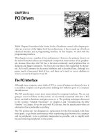
In this section, we look at the configuration registers that PCI devices contain. All
PCI devices feature at least a 256-byte address space. The first 64 bytes are standard-
ized, while the rest are device dependent. Figure 12-2 shows the layout of the device-
independent configuration space.
As the figure shows, some of the PCI configuration registers are required and some
are optional. Every PCI device must contain meaningful values in the required regis-
ters, whereas the contents of the optional registers depend on the actual capabilities
of the peripheral. The optional fields are not used unless the contents of the required
fields indicate that they are valid. Thus, the required fields assert the board’s capabil-
ities, including whether the other fields are usable.
It’s interesting to note that the PCI registers are always little-endian. Although the
standard is designed to be architecture independent, the PCI designers sometimes
show a slight bias toward the PC environment. The driver writer should be careful
about byte ordering when accessing multibyte configuration registers; code that
works on the PC might not work on other platforms. The Linux developers have
taken care of the byte-ordering problem (see the next section, “Accessing the Config-
uration Space”), but the issue must be kept in mind. If you ever need to convert data
from host order to PCI order or vice versa, you can resort to the functions defined in
<asm/byteorder.h>, introduced in Chapter 11, knowing that PCI byte order is little-
endian.
Figure 12-2. The standardized PCI configuration registers
- Required Register
- Optional Register
Vendor
ID
0x0 0x1 0x2 0x3 0x4 0x5 0x6 0x7 0x8 0x9 0xa 0xb 0xc 0xd 0xe 0xf
Device
ID
Command
Reg.
Status
Reg.
Revis-
ion
ID
Class Code Cache
Line
Latency
Timer
Header
Type
BIST
0x00
Base
Address 2
0x10
Base
Address 3
Base
Address 1
Base
Address 0
CardBus
CIS pointer
0x20
Subsytem
Vendor ID
Base
Address 5
Base
Address 4
Subsytem
Device ID
0x30
Expansion ROM
Base Address
Reserved
IRQ
Line
IRQ
Pin
Min_Gnt
Max_Lat
,ch12.1659 Page 308 Friday, January 21, 2005 3:08 PM
This is the Title of the Book, eMatter Edition
Copyright © 2005 O’Reilly & Associates, Inc. All rights reserved.
The PCI Interface
|
309
Describing all the configuration items is beyond the scope of this book. Usually, the
technical documentation released with each device describes the supported registers.
What we’re interested in is how a driver can look for its device and how it can access
the device’s configuration space.
Three or five PCI registers identify a device:
vendorID, deviceID, and class are the
three that are always used. Every PCI manufacturer assigns proper values to these
read-only registers, and the driver can use them to look for the device. Additionally,
the fields
subsystem vendorID and subsystem deviceID are sometimes set by the ven-
dor to further differentiate similar devices.
Let’s look at these registers in more detail:
vendorID
This 16-bit register identifies a hardware manufacturer. For instance, every Intel
device is marked with the same vendor number,
0x8086. There is a global regis-
try of such numbers, maintained by the PCI Special Interest Group, and manu-
facturers must apply to have a unique number assigned to them.
deviceID
This is another 16-bit register, selected by the manufacturer; no official registra-
tion is required for the device ID. This ID is usually paired with the vendor ID to
make a unique 32-bit identifier for a hardware device. We use the word signa-
ture to refer to the vendor and device ID pair. A device driver usually relies on
the signature to identify its device; you can find what value to look for in the
hardware manual for the target device.
class
Every peripheral device belongs to a class.Theclass register is a 16-bit value
whose top 8 bits identify the “base class” (or group). For example, “ethernet”
and “token ring” are two classes belonging to the “network” group, while the
“serial” and “parallel” classes belong to the “communication” group. Some driv-
ers can support several similar devices, each of them featuring a different signa-
ture but all belonging to the same class; these drivers can rely on the
class
register to identify their peripherals, as shown later.
subsystem vendorID
subsystem deviceID
These fields can be used for further identification of a device. If the chip is a
generic interface chip to a local (onboard) bus, it is often used in several com-
pletely different roles, and the driver must identify the actual device it is talking
with. The subsystem identifiers are used to this end.
Using these different identifiers, a PCI driver can tell the kernel what kind of devices it
supports. The
struct pci_device_id structure is used to define a list of the different
,ch12.1659 Page 309 Friday, January 21, 2005 3:08 PM
This is the Title of the Book, eMatter Edition
Copyright © 2005 O’Reilly & Associates, Inc. All rights reserved.
310
|
Chapter 12: PCI Drivers
types of PCI devices that a driver supports. This structure contains the following
fields:
__u32 vendor;
__u32 device;
These specify the PCI vendor and device IDs of a device. If a driver can handle
any vendor or device ID, the value PCI_ANY_ID should be used for these fields.
__u32 subvendor;
__u32 subdevice;
These specify the PCI subsystem vendor and subsystem device IDs of a device. If
a driver can handle any type of subsystem ID, the value PCI_ANY_ID should be
used for these fields.
__u32 class;
__u32 class_mask;
These two values allow the driver to specify that it supports a type of PCI class
device. The different classes of PCI devices (a VGA controller is one example)
are described in the PCI specification. If a driver can handle any type of sub-
system ID, the value
PCI_ANY_ID should be used for these fields.
kernel_ulong_t driver_data;
This value is not used to match a device but is used to hold information that the
PCI driver can use to differentiate between different devices if it wants to.
There are two helper macros that should be used to initialize a
struct pci_device_id
structure:
PCI_DEVICE(vendor, device)
This creates a struct pci_device_id that matches only the specific vendor and
device ID. The macro sets the
subvendor and subdevice fields of the structure to
PCI_ANY_ID.
PCI_DEVICE_CLASS(device_class, device_class_mask)
This creates a struct pci_device_id that matches a specific PCI class.
An example of using these macros to define the type of devices a driver supports can
be found in the following kernel files:
drivers/usb/host/ehci-hcd.c:
static const struct pci_device_id pci_ids[ ] = { {
/* handle any USB 2.0 EHCI controller */
PCI_DEVICE_CLASS(((PCI_CLASS_SERIAL_USB << 8) | 0x20), ~0),
.driver_data = (unsigned long) &ehci_driver,
},
{ /* end: all zeroes */ }
};
drivers/i2c/busses/i2c-i810.c:
,ch12.1659 Page 310 Friday, January 21, 2005 3:08 PM
This is the Title of the Book, eMatter Edition
Copyright © 2005 O’Reilly & Associates, Inc. All rights reserved.
The PCI Interface
|
311
static struct pci_device_id i810_ids[ ] = {
{ PCI_DEVICE(PCI_VENDOR_ID_INTEL, PCI_DEVICE_ID_INTEL_82810_IG1) },
{ PCI_DEVICE(PCI_VENDOR_ID_INTEL, PCI_DEVICE_ID_INTEL_82810_IG3) },
{ PCI_DEVICE(PCI_VENDOR_ID_INTEL, PCI_DEVICE_ID_INTEL_82810E_IG) },
{ PCI_DEVICE(PCI_VENDOR_ID_INTEL, PCI_DEVICE_ID_INTEL_82815_CGC) },
{ PCI_DEVICE(PCI_VENDOR_ID_INTEL, PCI_DEVICE_ID_INTEL_82845G_IG) },
{ 0, },
};
These examples create a list of struct pci_device_id structures, with an empty struc-
ture set to all zeros as the last value in the list. This array of IDs is used in the
struct
pci_driver
(described below), and it is also used to tell user space which devices this
specific driver supports.
MODULE_DEVICE_TABLE
This pci_device_id structure needs to be exported to user space to allow the hotplug
and module loading systems know what module works with what hardware devices.
The macro
MODULE_DEVICE_TABLE accomplishes this. An example is:
MODULE_DEVICE_TABLE(pci, i810_ids);
This statement creates a local variable called __mod_pci_device_table that points to
the list of
struct pci_device_id. Later in the kernel build process, the depmod pro-
gram searches all modules for the symbol
__mod_pci_device_table. If that symbol is
found, it pulls the data out of the module and adds it to the file /lib/modules/
KERNEL_VERSION/modules.pcimap. After
depmod completes, all PCI devices that
are supported by modules in the kernel are listed, along with their module names, in
that file. When the kernel tells the hotplug system that a new PCI device has been
found, the hotplug system uses the modules.pcimap file to find the proper driver to
load.
Registering a PCI Driver
The main structure that all PCI drivers must create in order to be registered with the
kernel properly is the
struct pci_driver structure. This structure consists of a num-
ber of function callbacks and variables that describe the PCI driver to the PCI core.
Here are the fields in this structure that a PCI driver needs to be aware of:
const char *name;
The name of the driver. It must be unique among all PCI drivers in the kernel
and is normally set to the same name as the module name of the driver. It shows
up in sysfs under /sys/bus/pci/drivers/ when the driver is in the kernel.
const struct pci_device_id *id_table;
Pointer to the struct pci_device_id table described earlier in this chapter.
,ch12.1659 Page 311 Friday, January 21, 2005 3:08 PM
This is the Title of the Book, eMatter Edition
Copyright © 2005 O’Reilly & Associates, Inc. All rights reserved.
312
|
Chapter 12: PCI Drivers
int (*probe) (struct pci_dev *dev, const struct pci_device_id *id);
Pointer to the probe function in the PCI driver. This function is called by the PCI
core when it has a
struct pci_dev that it thinks this driver wants to control. A
pointer to the struct pci_device_id that the PCI core used to make this decision
is also passed to this function. If the PCI driver claims the
struct pci_dev that is
passed to it, it should initialize the device properly and return
0. If the driver
does not want to claim the device, or an error occurs, it should return a negative
error value. More details about this function follow later in this chapter.
void (*remove) (struct pci_dev *dev);
Pointer to the function that the PCI core calls when the struct pci_dev is being
removed from the system, or when the PCI driver is being unloaded from the
kernel. More details about this function follow later in this chapter.
int (*suspend) (struct pci_dev *dev, u32 state);
Pointer to the function that the PCI core calls when the struct pci_dev is being
suspended. The suspend state is passed in the
state variable. This function is
optional; a driver does not have to provide it.
int (*resume) (struct pci_dev *dev);
Pointer to the function that the PCI core calls when the struct pci_dev is being
resumed. It is always called after
suspend has been called. This function is
optional; a driver does not have to provide it.
In summary, to create a proper
struct pci_driver structure, only four fields need to
be initialized:
static struct pci_driver pci_driver = {
.name = "pci_skel",
.id_table = ids,
.probe = probe,
.remove = remove,
};
To register the struct pci_driver with the PCI core, a call to pci_register_driver is
made with a pointer to the
struct pci_driver. This is traditionally done in the mod-
ule initialization code for the PCI driver:
static int __init pci_skel_init(void)
{
return pci_register_driver(&pci_driver);
}
Note that the pci_register_driver function either returns a negative error number or 0
if everything was registered successfully. It does not return the number of devices
that were bound to the driver or an error number if no devices were bound to the
,ch12.1659 Page 312 Friday, January 21, 2005 3:08 PM
This is the Title of the Book, eMatter Edition
Copyright © 2005 O’Reilly & Associates, Inc. All rights reserved.
The PCI Interface
|
313
driver. This is a change from kernels prior to the 2.6 release and was done because of
the following situations:
• On systems that support PCI hotplug, or CardBus systems, a PCI device can
appear or disappear at any point in time. It is helpful if drivers can be loaded
before the device appears, to reduce the time it takes to initialize a device.
• The 2.6 kernel allows new PCI IDs to be dynamically allocated to a driver after it
has been loaded. This is done through the file
new_id that is created in all PCI
driver directories in sysfs. This is very useful if a new device is being used that
the kernel doesn’t know about just yet. A user can write the PCI ID values to the
new_id file, and then the driver binds to the new device. If a driver was not
allowed to load until a device was present in the system, this interface would not
be able to work.
When the PCI driver is to be unloaded, the
struct pci_driver needs to be unregis-
tered from the kernel. This is done with a call to pci_unregister_driver. When this call
happens, any PCI devices that were currently bound to this driver are removed, and
the remove function for this PCI driver is called before the pci_unregister_driver func-
tion returns.
static void __exit pci_skel_exit(void)
{
pci_unregister_driver(&pci_driver);
}
Old-Style PCI Probing
In older kernel versions, the function, pci_register_driver, was not always used by
PCI drivers. Instead, they would either walk the list of PCI devices in the system by
hand, or they would call a function that could search for a specific PCI device. The
ability to walk the list of PCI devices in the system within a driver has been removed
from the 2.6 kernel in order to prevent drivers from crashing the kernel if they hap-
pened to modify the PCI device lists while a device was being removed at the same
time.
If the ability to find a specific PCI device is really needed, the following functions are
available:
struct pci_dev *pci_get_device(unsigned int vendor, unsigned int device,
struct pci_dev *from);
This function scans the list of PCI devices currently present in the system, and if
the input arguments match the specified
vendor and device IDs, it increments
the reference count on the
struct pci_dev variable found, and returns it to the
caller. This prevents the structure from disappearing without any notice and
ensures that the kernel does not oops. After the driver is done with the
struct
pci_dev
returned by the function, it must call the function pci_dev_put to decre-
,ch12.1659 Page 313 Friday, January 21, 2005 3:08 PM
This is the Title of the Book, eMatter Edition
Copyright © 2005 O’Reilly & Associates, Inc. All rights reserved.
314
|
Chapter 12: PCI Drivers
ment the usage count properly back to allow the kernel to clean up the device if
it is removed.
The
from argument is used to get hold of multiple devices with the same signa-
ture; the argument should point to the last device that has been found, so that
the search can continue instead of restarting from the head of the list. To find
the first device,
from is specified as NULL. If no (further) device is found, NULL is
returned.
An example of how to use this function properly is:
struct pci_dev *dev;
dev = pci_get_device(PCI_VENDOR_FOO, PCI_DEVICE_FOO, NULL);
if (dev) {
/* Use the PCI device */
pci_dev_put(dev);
}
This function can not be called from interrupt context. If it is, a warning is
printed out to the system log.
struct pci_dev *pci_get_subsys(unsigned int vendor, unsigned int device,
unsigned int ss_vendor, unsigned int ss_device, struct pci_dev *from);
This function works just like pci_get_device, but it allows the subsystem vendor
and subsystem device IDs to be specified when looking for the device.
This function can not be called from interrupt context. If it is, a warning is
printed out to the system log.
struct pci_dev *pci_get_slot(struct pci_bus *bus, unsigned int devfn);
This function searches the list of PCI devices in the system on the specified
struct pci_bus for the specified device and function number of the PCI device. If
a device is found that matches, its reference count is incremented and a pointer
to it is returned. When the caller is finished accessing the
struct pci_dev, it must
call pci_dev_put.
All of these functions can not be called from interrupt context. If they are, a warning
is printed out to the system log.
Enabling the PCI Device
In the probe function for the PCI driver, before the driver can access any device resource
(I/O region or interrupt) of the PCI device, the driver must call the pci_enable_device
function:
int pci_enable_device(struct pci_dev *dev);
This function actually enables the device. It wakes up the device and in some
cases also assigns its interrupt line and I/O regions. This happens, for example,
with CardBus devices (which have been made completely equivalent to PCI at
the driver level).
,ch12.1659 Page 314 Friday, January 21, 2005 3:08 PM
This is the Title of the Book, eMatter Edition
Copyright © 2005 O’Reilly & Associates, Inc. All rights reserved.
The PCI Interface
|
315
Accessing the Configuration Space
After the driver has detected the device, it usually needs to read from or write to the
three address spaces: memory, port, and configuration. In particular, accessing the
configuration space is vital to the driver, because it is the only way it can find out
where the device is mapped in memory and in the I/O space.
Because the microprocessor has no way to access the configuration space directly,
the computer vendor has to provide a way to do it. To access configuration space,
the CPU must write and read registers in the PCI controller, but the exact implemen-
tation is vendor dependent and not relevant to this discussion, because Linux offers a
standard interface to access the configuration space.
As far as the driver is concerned, the configuration space can be accessed through 8-
bit, 16-bit, or 32-bit data transfers. The relevant functions are prototyped in <linux/
pci.h>:
int pci_read_config_byte(struct pci_dev *dev, int where, u8 *val);
int pci_read_config_word(struct pci_dev *dev, int where, u16 *val);
int pci_read_config_dword(struct pci_dev *dev, int where, u32 *val);
Read one, two, or four bytes from the configuration space of the device identi-
fied by
dev.Thewhere argument is the byte offset from the beginning of the con-
figuration space. The value fetched from the configuration space is returned
through the
val pointer, and the return value of the functions is an error code.
The word and dword functions convert the value just read from little-endian to
the native byte order of the processor, so you need not deal with byte ordering.
int pci_write_config_byte(struct pci_dev *dev, int where, u8 val);
int pci_write_config_word(struct pci_dev *dev, int where, u16 val);
int pci_write_config_dword(struct pci_dev *dev, int where, u32 val);
Write one, two, or four bytes to the configuration space. The device is identified
by
dev as usual, and the value being written is passed as val.Theword and
dword functions convert the value to little-endian before writing to the periph-
eral device.
All of the previous functions are implemented as inline functions that really call the
following functions. Feel free to use these functions instead of the above in case the
driver does not have access to a
struct pci_dev at any paticular moment in time:
int pci_bus_read_config_byte (struct pci_bus *bus, unsigned int devfn, int
where, u8 *val);
int pci_bus_read_config_word (struct pci_bus *bus, unsigned int devfn, int
where, u16 *val);
int pci_bus_read_config_dword (struct pci_bus *bus, unsigned int devfn, int
where, u32 *val);
Just like the pci_read_ functions, but struct pci_bus * and devfn variables are
needed instead of a
struct pci_dev *.
,ch12.1659 Page 315 Friday, January 21, 2005 3:08 PM
This is the Title of the Book, eMatter Edition
Copyright © 2005 O’Reilly & Associates, Inc. All rights reserved.
316
|
Chapter 12: PCI Drivers
int pci_bus_write_config_byte (struct pci_bus *bus, unsigned int devfn, int
where, u8 val);
int pci_bus_write_config_word (struct pci_bus *bus, unsigned int devfn, int
where, u16 val);
int pci_bus_write_config_dword (struct pci_bus *bus, unsigned int devfn, int
where, u32 val);
Just like the pci_write_ functions, but struct pci_bus * and devfn variables are
needed instead of a
struct pci_dev *.
The best way to address the configuration variables using the pci_read_ functions is
by means of the symbolic names defined in <linux/pci.h>. For example, the follow-
ing small function retrieves the revision ID of a device by passing the symbolic name
for
where to pci_read_config_byte:
static unsigned char skel_get_revision(struct pci_dev *dev)
{
u8 revision;
pci_read_config_byte(dev, PCI_REVISION_ID, &revision);
return revision;
}
Accessing the I/O and Memory Spaces
A PCI device implements up to six I/O address regions. Each region consists of either
memory or I/O locations. Most devices implement their I/O registers in memory
regions, because it’s generally a saner approach (as explained in the section “I/O
Ports and I/O Memory,” in Chapter 9). However, unlike normal memory, I/O regis-
ters should not be cached by the CPU because each access can have side effects. The
PCI device that implements I/O registers as a memory region marks the difference by
setting a “memory-is-prefetchable” bit in its configuration register.
*
If the memory
region is marked as prefetchable, the CPU can cache its contents and do all sorts of
optimization with it; nonprefetchable memory access, on the other hand, can’t be
optimized because each access can have side effects, just as with I/O ports. Peripher-
als that map their control registers to a memory address range declare that range as
nonprefetchable, whereas something like video memory on PCI boards is prefetch-
able. In this section, we use the word region to refer to a generic I/O address space
that is memory-mapped or port-mapped.
An interface board reports the size and current location of its regions using configura-
tion registers—the six 32-bit registers shown in Figure 12-2, whose symbolic names
are
PCI_BASE_ADDRESS_0 through PCI_BASE_ADDRESS_5. Since the I/O space defined by
PCI is a 32-bit address space, it makes sense to use the same configuration interface
* The information lives in one of the low-order bits of the base address PCI registers. The bits are defined in
<linux/pci.h>.
,ch12.1659 Page 316 Friday, January 21, 2005 3:08 PM
This is the Title of the Book, eMatter Edition
Copyright © 2005 O’Reilly & Associates, Inc. All rights reserved.
The PCI Interface
|
317
for memory and I/O. If the device uses a 64-bit address bus, it can declare regions in
the 64-bit memory space by using two consecutive
PCI_BASE_ADDRESS registers for each
region, low bits first. It is possible for one device to offer both 32-bit regions and 64-
bit regions.
In the kernel, the I/O regions of PCI devices have been integrated into the generic
resource management. For this reason, you don’t need to access the configuration
variables in order to know where your device is mapped in memory or I/O space.
The preferred interface for getting region information consists of the following
functions:
unsigned long pci_resource_start(struct pci_dev *dev, int bar);
The function returns the first address (memory address or I/O port number)
associated with one of the six PCI I/O regions. The region is selected by the inte-
ger
bar (the base address register), ranging from 0–5 (inclusive).
unsigned long pci_resource_end(struct pci_dev *dev, int bar);
The function returns the last address that is part of the I/O region number bar.
Note that this is the last usable address, not the first address after the region.
unsigned long pci_resource_flags(struct pci_dev *dev, int bar);
This function returns the flags associated with this resource.
Resource flags are used to define some features of the individual resource. For PCI
resources associated with PCI I/O regions, the information is extracted from the base
address registers, but can come from elsewhere for resources not associated with PCI
devices.
All resource flags are defined in <linux/ioport.h>; the most important are:
IORESOURCE_IO
IORESOURCE_MEM
If the associated I/O region exists, one and only one of these flags is set.
IORESOURCE_PREFETCH
IORESOURCE_READONLY
These flags tell whether a memory region is prefetchable and/or write protected.
The latter flag is never set for PCI resources.
By making use of the pci_resource_ functions, a device driver can completely ignore
the underlying PCI registers, since the system already used them to structure
resource information.
PCI Interrupts
As far as interrupts are concerned, PCI is easy to handle. By the time Linux boots,
the computer’s firmware has already assigned a unique interrupt number to the
device, and the driver just needs to use it. The interrupt number is stored in configu-
ration register 60 (
PCI_INTERRUPT_LINE), which is one byte wide. This allows for as
,ch12.1659 Page 317 Friday, January 21, 2005 3:08 PM
This is the Title of the Book, eMatter Edition
Copyright © 2005 O’Reilly & Associates, Inc. All rights reserved.
318
|
Chapter 12: PCI Drivers
many as 256 interrupt lines, but the actual limit depends on the CPU being used.
The driver doesn’t need to bother checking the interrupt number, because the value
found in
PCI_INTERRUPT_LINE is guaranteed to be the right one.
If the device doesn’t support interrupts, register 61 (
PCI_INTERRUPT_PIN)is0; other-
wise, it’s nonzero. However, since the driver knows if its device is interrupt driven or
not, it doesn’t usually need to read
PCI_INTERRUPT_PIN.
Thus, PCI-specific code for dealing with interrupts just needs to read the configura-
tion byte to obtain the interrupt number that is saved in a local variable, as shown in
the following code. Beyond that, the information in Chapter 10 applies.
result = pci_read_config_byte(dev, PCI_INTERRUPT_LINE, &myirq);
if (result) {
/* deal with error */
}
The rest of this section provides additional information for the curious reader but
isn’t needed for writing drivers.
A PCI connector has four interrupt pins, and peripheral boards can use any or all of
them. Each pin is individually routed to the motherboard’s interrupt controller, so
interrupts can be shared without any electrical problems. The interrupt controller is
then responsible for mapping the interrupt wires (pins) to the processor’s hardware;
this platform-dependent operation is left to the controller in order to achieve plat-
form independence in the bus itself.
The read-only configuration register located at
PCI_INTERRUPT_PIN is used to tell the
computer which single pin is actually used. It’s worth remembering that each device
board can host up to eight devices; each device uses a single interrupt pin and reports
it in its own configuration register. Different devices on the same device board can
use different interrupt pins or share the same one.
The
PCI_INTERRUPT_LINE register, on the other hand, is read/write. When the com-
puter is booted, the firmware scans its PCI devices and sets the register for each
device according to how the interrupt pin is routed for its PCI slot. The value is
assigned by the firmware, because only the firmware knows how the motherboard
routes the different interrupt pins to the processor. For the device driver, however,
the
PCI_INTERRUPT_LINE register is read-only. Interestingly, recent versions of the
Linux kernel under some circumstances can assign interrupt lines without resorting
to the BIOS.
Hardware Abstractions
We complete the discussion of PCI by taking a quick look at how the system han-
dles the plethora of PCI controllers available on the marketplace. This is just an
informational section, meant to show the curious reader how the object-oriented lay-
out of the kernel extends down to the lowest levels.
,ch12.1659 Page 318 Friday, January 21, 2005 3:08 PM
This is the Title of the Book, eMatter Edition
Copyright © 2005 O’Reilly & Associates, Inc. All rights reserved.
A Look Back: ISA
|
319
The mechanism used to implement hardware abstraction is the usual structure con-
taining methods. It’s a powerful technique that adds just the minimal overhead of
dereferencing a pointer to the normal overhead of a function call. In the case of PCI
management, the only hardware-dependent operations are the ones that read and
write configuration registers, because everything else in the PCI world is accom-
plished by directly reading and writing the I/O and memory address spaces, and
those are under direct control of the CPU.
Thus, the relevant structure for configuration register access includes only two fields:
struct pci_ops {
int (*read)(struct pci_bus *bus, unsigned int devfn, int where, int size,
u32 *val);
int (*write)(struct pci_bus *bus, unsigned int devfn, int where, int size,
u32 val);
};
The structure is defined in <linux/pci.h> and used by drivers/pci/pci.c, where the
actual public functions are defined.
The two functions that act on the PCI configuration space have more overhead
than dereferencing a pointer; they use cascading pointers due to the high object-
orientedness of the code, but the overhead is not an issue in operations that are
performed quite rarely and never in speed-critical paths. The actual implementa-
tion of pci_read_config_byte(dev, where, val), for instance, expands to:
dev->bus->ops->read(bus, devfn, where, 8, val);
The various PCI buses in the system are detected at system boot, and that’s when the
struct pci_bus items are created and associated with their features, including the ops
field.
Implementing hardware abstraction via “hardware operations” data structures is typ-
ical in the Linux kernel. One important example is the
struct alpha_machine_vector
data structure. It is defined in <asm-alpha/machvec.h> and takes care of everything
that may change across different Alpha-based computers.
A Look Back: ISA
The ISA bus is quite old in design and is a notoriously poor performer, but it still
holds a good part of the market for extension devices. If speed is not important and
you want to support old motherboards, an ISA implementation is preferable to PCI.
An additional advantage of this old standard is that if you are an electronic hobbyist,
you can easily build your own ISA devices, something definitely not possible with
PCI.
,ch12.1659 Page 319 Friday, January 21, 2005 3:08 PM
This is the Title of the Book, eMatter Edition
Copyright © 2005 O’Reilly & Associates, Inc. All rights reserved.
320
|
Chapter 12: PCI Drivers
On the other hand, a great disadvantage of ISA is that it’s tightly bound to the PC
architecture; the interface bus has all the limitations of the 80286 processor and
causes endless pain to system programmers. The other great problem with the ISA
design (inherited from the original IBM PC) is the lack of geographical addressing,
which has led to many problems and lengthy unplug-rejumper-plug-test cycles to
add new devices. It’s interesting to note that even the oldest Apple II computers were
already exploiting geographical addressing, and they featured jumperless expansion
boards.
Despite its great disadvantages, ISA is still used in several unexpected places. For
example, the VR41xx series of MIPS processors used in several palmtops features an
ISA-compatible expansion bus, strange as it seems. The reason behind these unex-
pected uses of ISA is the extreme low cost of some legacy hardware, such as 8390-
based Ethernet cards, so a CPU with ISA electrical signaling can easily exploit the
awful, but cheap, PC devices.
Hardware Resources
An ISA device can be equipped with I/O ports, memory areas, and interrupt lines.
Even though the x86 processors support 64 KB of I/O port memory (i.e., the proces-
sor asserts 16 address lines), some old PC hardware decodes only the lowest 10
address lines. This limits the usable address space to 1024 ports, because any address
in the range 1 KB to 64 KB is mistaken for a low address by any device that decodes
only the low address lines. Some peripherals circumvent this limitation by mapping
only one port into the low kilobyte and using the high address lines to select between
different device registers. For example, a device mapped at
0x340 can safely use port
0x740, 0xB40, and so on.
If the availability of I/O ports is limited, memory access is still worse. An ISA device
can use only the memory range between 640 KB and 1 MB and between 15 MB and
16 MB for I/O register and device control. The 640-KB to 1-MB range is used by the
PC BIOS, by VGA-compatible video boards, and by various other devices, leaving lit-
tle space available for new devices. Memory at 15 MB, on the other hand, is not
directly supported by Linux, and hacking the kernel to support it is a waste of pro-
gramming time nowadays.
The third resource available to ISA device boards is interrupt lines. A limited num-
ber of interrupt lines is routed to the ISA bus, and they are shared by all the interface
boards. As a result, if devices aren’t properly configured, they can find themselves
using the same interrupt lines.
,ch12.1659 Page 320 Friday, January 21, 2005 3:08 PM
This is the Title of the Book, eMatter Edition
Copyright © 2005 O’Reilly & Associates, Inc. All rights reserved.
A Look Back: ISA
|
321
Although the original ISA specification doesn’t allow interrupt sharing across
devices, most device boards allow it.
*
Interrupt sharing at the software level is
described in the section “Interrupt Sharing,” in Chapter 10.
ISA Programming
As far as programming is concerned, there’s no specific aid in the kernel or the BIOS
to ease access to ISA devices (like there is, for example, for PCI). The only facilities
you can use are the registries of I/O ports and IRQ lines, described in the section
“Installing an Interrupt Handler” in Chapter 10.
The programming techniques shown throughout the first part of this book apply to
ISA devices; the driver can probe for I/O ports, and the interrupt line must be auto-
detected with one of the techniques shown in the section “Autodetecting the IRQ
Number” in Chapter 10.
The helper functions isa_readb and friends have been briefly introduced in the sec-
tion “Using I/O Memory” in Chapter 9, and there’s nothing more to say about them.
The Plug-and-Play Specification
Some new ISA device boards follow peculiar design rules and require a special initial-
ization sequence intended to simplify installation and configuration of add-on inter-
face boards. The specification for the design of these boards is called plug and play
(PnP) and consists of a cumbersome rule set for building and configuring jumperless
ISA devices. PnP devices implement relocatable I/O regions; the PC’s BIOS is respon-
sible for the relocation—reminiscent of PCI.
In short, the goal of PnP is to obtain the same flexibility found in PCI devices with-
out changing the underlying electrical interface (the ISA bus). To this end, the specs
define a set of device-independent configuration registers and a way to geographi-
cally address the interface boards, even though the physical bus doesn’t carry per-
board (geographical) wiring—every ISA signal line connects to every available slot.
Geographical addressing works by assigning a small integer, called the card select
number (CSN), to each PnP peripheral in the computer. Each PnP device features a
unique serial identifier, 64 bits wide, that is hardwired into the peripheral board.
CSN assignment uses the unique serial number to identify the PnP devices. But the
CSNs can be assigned safely only at boot time, which requires the BIOS to be PnP
* The problem with interrupt sharing is a matter of electrical engineering: if a device drives the signal line inac-
tive—by applying a low-impedance voltage level—the interrupt can’t be shared. If, on the other hand, the
device uses a pull-up resistor to the inactive logic level, sharing is possible. This is the norm nowadays. How-
ever, there’s still a potential risk of losing interrupt events since ISA interrupts are edge triggered instead of
level triggered. Edge-triggered interrupts are easier to implement in hardware but don’t lend themselves to
safe sharing.
,ch12.1659 Page 321 Friday, January 21, 2005 3:08 PM
This is the Title of the Book, eMatter Edition
Copyright © 2005 O’Reilly & Associates, Inc. All rights reserved.
322
|
Chapter 12: PCI Drivers
aware. For this reason, old computers require the user to obtain and insert a specific
configuration diskette, even if the device is PnP capable.
Interface boards following the PnP specs are complicated at the hardware level. They
are much more elaborate than PCI boards and require complex software. It’s not
unusual to have difficulty installing these devices, and even if the installation goes
well, you still face the performance constraints and the limited I/O space of the ISA
bus. It’s much better to install PCI devices whenever possible and enjoy the new
technology instead.
If you are interested in the PnP configuration software, you can browse drivers/net/
3c509.c, whose probing function deals with PnP devices. The 2.6 kernel saw a lot of
work in the PnP device support area, so a lot of the inflexible interfaces have been
cleaned up compared to previous kernel releases.
PC/104 and PC/104+
Currently in the industrial world, two bus architectures are quite fashionable: PC/104
and PC/104+. Both are standard in PC-class single-board computers.
Both standards refer to specific form factors for printed circuit boards, as well as
electrical/mechanical specifications for board interconnections. The practical advan-
tage of these buses is that they allow circuit boards to be stacked vertically using a
plug-and-socket kind of connector on one side of the device.
The electrical and logical layout of the two buses is identical to ISA (PC/104) and
PCI (PC/104+), so software won’t notice any difference between the usual desktop
buses and these two.
Other PC Buses
PCI and ISA are the most commonly used peripheral interfaces in the PC world, but
they aren’t the only ones. Here’s a summary of the features of other buses found in
the PC market.
MCA
Micro Channel Architecture (MCA) is an IBM standard used in PS/2 computers and
some laptops. At the hardware level, Micro Channel has more features than ISA. It
supports multimaster DMA, 32-bit address and data lines, shared interrupt lines, and
geographical addressing to access per-board configuration registers. Such registers
are called Programmable Option Select (POS), but they don’t have all the features of
the PCI registers. Linux support for Micro Channel includes functions that are
exported to modules.
,ch12.1659 Page 322 Friday, January 21, 2005 3:08 PM
This is the Title of the Book, eMatter Edition
Copyright © 2005 O’Reilly & Associates, Inc. All rights reserved.
SBus
|
323
A device driver can read the integer value MCA_bus to see if it is running on a Micro
Channel computer. If the symbol is a preprocessor macro, the macro
MCA_bus__is_a_
macro
is defined as well. If MCA_bus__is_a_macro is undefined, then MCA_bus is an inte-
ger variable exported to modularized code. Both MCA_BUS and MCA_bus__is_a_macro
are defined in <asm/processor.h>.
EISA
The Extended ISA (EISA) bus is a 32-bit extension to ISA, with a compatible inter-
face connector; ISA device boards can be plugged into an EISA connector. The addi-
tional wires are routed under the ISA contacts.
Like PCI and MCA, the EISA bus is designed to host jumperless devices, and it has
the same features as MCA: 32-bit address and data lines, multimaster DMA, and
shared interrupt lines. EISA devices are configured by software, but they don’t need
any particular operating system support. EISA drivers already exist in the Linux ker-
nel for Ethernet devices and SCSI controllers.
An EISA driver checks the value
EISA_bus to determine if the host computer carries
an EISA bus. Like
MCA_bus, EISA_bus is either a macro or a variable, depending on
whether
EISA_bus__is_a_macro is defined. Both symbols are defined in <asm/
processor.h>.
The kernel has full EISA support for devices with sysfs and resource management
functionality. This is located in the drivers/eisa directory.
VLB
Another extension to ISA is the VESA Local Bus (VLB) interface bus, which extends
the ISA connectors by adding a third lengthwise slot. A device can just plug into this
extra connector (without plugging in the two associated ISA connectors), because
the VLB slot duplicates all important signals from the ISA connectors. Such “standal-
one” VLB peripherals not using the ISA slot are rare, because most devices need to
reach the back panel so that their external connectors are available.
The VESA bus is much more limited in its capabilities than the EISA, MCA, and PCI
buses and is disappearing from the market. No special kernel support exists for VLB.
However, both the Lance Ethernet driver and the IDE disk driver in Linux 2.0 can
deal with VLB versions of their devices.
SBus
While most computers nowadays are equipped with a PCI or ISA interface bus, most
older SPARC-based workstations use SBus to connect their peripherals.
,ch12.1659 Page 323 Friday, January 21, 2005 3:08 PM
This is the Title of the Book, eMatter Edition
Copyright © 2005 O’Reilly & Associates, Inc. All rights reserved.
324
|
Chapter 12: PCI Drivers
SBus is quite an advanced design, although it has been around for a long time. It is
meant to be processor independent (even though only SPARC computers use it) and
is optimized for I/O peripheral boards. In other words, you can’t plug additional
RAM into SBus slots (RAM expansion boards have long been forgotten even in the
ISA world, and PCI does not support them either). This optimization is meant to
simplify the design of both hardware devices and system software, at the expense of
some additional complexity in the motherboard.
This I/O bias of the bus results in peripherals using virtual addresses to transfer data,
thus bypassing the need to allocate a contiguous DMA buffer. The motherboard is
responsible for decoding the virtual addresses and mapping them to physical
addresses. This requires attaching an MMU (memory management unit) to the bus;
the chipset in charge of the task is called IOMMU. Although somehow more com-
plex than using physical addresses on the interface bus, this design is greatly simpli-
fied by the fact that SPARC processors have always been designed by keeping the
MMU core separate from the CPU core (either physically or at least conceptually).
Actually, this design choice is shared by other smart processor designs and is benefi-
cial overall. Another feature of this bus is that device boards exploit massive geo-
graphical addressing, so there’s no need to implement an address decoder in every
peripheral or to deal with address conflicts.
SBus peripherals use the Forth language in their PROMs to initialize themselves.
Forth was chosen because the interpreter is lightweight and, therefore, can be easily
implemented in the firmware of any computer system. In addition, the SBus specifi-
cation outlines the boot process, so that compliant I/O devices fit easily into the sys-
tem and are recognized at system boot. This was a great step to support multi-
platform devices; it’s a completely different world from the PC-centric ISA stuff we
were used to. However, it didn’t succeed for a variety of commercial reasons.
Although current kernel versions offer quite full-featured support for SBus devices,
the bus is used so little nowadays that it’s not worth covering in detail here. Inter-
ested readers can look at source files in arch/sparc/kernel and arch/sparc/mm.
NuBus
Another interesting, but nearly forgotten, interface bus is NuBus. It is found on older
Mac computers (those with the M68k family of CPUs).
All of the bus is memory-mapped (like everything with the M68k), and the devices
are only geographically addressed. This is good and typical of Apple, as the much
,ch12.1659 Page 324 Friday, January 21, 2005 3:08 PM
This is the Title of the Book, eMatter Edition
Copyright © 2005 O’Reilly & Associates, Inc. All rights reserved.
Quick Reference
|
325
older Apple II already had a similar bus layout. What is bad is that it’s almost impos-
sible to find documentation on NuBus, due to the close-everything policy Apple has
always followed with its Mac computers (and unlike the previous Apple II, whose
source code and schematics were available at little cost).
The file drivers/nubus/nubus.c includes almost everything we know about this bus,
and it’s interesting reading; it shows how much hard reverse engineering developers
had to do.
External Buses
One of the most recent entries in the field of interface buses is the whole class of
external buses. This includes USB, FireWire, and IEEE1284 (parallel-port-based
external bus). These interfaces are somewhat similar to older and not-so-external
technology, such as PCMCIA/CardBus and even SCSI.
Conceptually, these buses are neither full-featured interface buses (like PCI is) nor
dumb communication channels (like the serial ports are). It’s hard to classify the
software that is needed to exploit their features, as it’s usually split into two levels:
the driver for the hardware controller (like drivers for PCI SCSI adaptors or PCI con-
trollers introduced in the section “The PCI Interface”) and the driver for the specific
“client” device (like sd.c handles generic SCSI disks and so-called PCI drivers deal
with cards plugged in the bus).
Quick Reference
This section summarizes the symbols introduced in the chapter:
#include <linux/pci.h>
Header that includes symbolic names for the PCI registers and several vendor
and device ID values.
struct pci_dev;
Structure that represents a PCI device within the kernel.
struct pci_driver;
Structure that represents a PCI driver. All PCI drivers must define this.
struct pci_device_id;
Structure that describes the types of PCI devices this driver supports.
int pci_register_driver(struct pci_driver *drv);
int pci_module_init(struct pci_driver *drv);
void pci_unregister_driver(struct pci_driver *drv);
Functions that register or unregister a PCI driver from the kernel.
,ch12.1659 Page 325 Friday, January 21, 2005 3:08 PM
This is the Title of the Book, eMatter Edition
Copyright © 2005 O’Reilly & Associates, Inc. All rights reserved.
326
|
Chapter 12: PCI Drivers
struct pci_dev *pci_find_device(unsigned int vendor, unsigned int device,
struct pci_dev *from);
struct pci_dev *pci_find_device_reverse(unsigned int vendor, unsigned int
device, const struct pci_dev *from);
struct pci_dev *pci_find_subsys (unsigned int vendor, unsigned int device,
unsigned int ss_vendor, unsigned int ss_device, const struct pci_dev *from);
struct pci_dev *pci_find_class(unsigned int class, struct pci_dev *from);
Functions that search the device list for devices with a specific signature or those
belonging to a specific class. The return value is
NULL if none is found. from is
used to continue a search; it must be
NULL the first time you call either function,
and it must point to the device just found if you are searching for more devices.
These functions are not recommended to be used, use the
pci_get_ variants
instead.
struct pci_dev *pci_get_device(unsigned int vendor, unsigned int device,
struct pci_dev *from);
struct pci_dev *pci_get_subsys(unsigned int vendor, unsigned int device,
unsigned int ss_vendor, unsigned int ss_device, struct pci_dev *from);
struct pci_dev *pci_get_slot(struct pci_bus *bus, unsigned int devfn);
Functions that search the device list for devices with a specific signature or
belonging to a specific class. The return value is
NULL if none is found. from is
used to continue a search; it must be
NULL the first time you call either function,
and it must point to the device just found if you are searching for more devices.
The structure returned has its reference count incremented, and after the caller is
finished with it, the function pci_dev_put must be called.
int pci_read_config_byte(struct pci_dev *dev, int where, u8 *val);
int pci_read_config_word(struct pci_dev *dev, int where, u16 *val);
int pci_read_config_dword(struct pci_dev *dev, int where, u32 *val);
int pci_write_config_byte (struct pci_dev *dev, int where, u8 *val);
int pci_write_config_word (struct pci_dev *dev, int where, u16 *val);
int pci_write_config_dword (struct pci_dev *dev, int where, u32 *val);
Functions that read or write a PCI configuration register. Although the Linux
kernel takes care of byte ordering, the programmer must be careful about byte
ordering when assembling multibyte values from individual bytes. The PCI bus
is little-endian.
int pci_enable_device(struct pci_dev *dev);
Enables a PCI device.
unsigned long pci_resource_start(struct pci_dev *dev, int bar);
unsigned long pci_resource_end(struct pci_dev *dev, int bar);
unsigned long pci_resource_flags(struct pci_dev *dev, int bar);
Functions that handle PCI device resources.
,ch12.1659 Page 326 Friday, January 21, 2005 3:08 PM