Báo cáo khoa học: " Systematisation of spatial uncertainties for comparison between a MR and a CT-based radiotherapy workflow for prostate treatments" pptx
Bạn đang xem bản rút gọn của tài liệu. Xem và tải ngay bản đầy đủ của tài liệu tại đây (388.28 KB, 9 trang )
BioMed Central
Page 1 of 9
(page number not for citation purposes)
Radiation Oncology
Open Access
Research
Systematisation of spatial uncertainties for comparison between a
MR and a CT-based radiotherapy workflow for prostate treatments
Tufve Nyholm*
1
, Morgan Nyberg
2
, Magnus G Karlsson
3
and
Mikael Karlsson
4
Address:
1
Department of radiation sciences (Oncology), Umeå University Hospital, 90187 Umeå, Sweden,
2
Information and Communication
Technology, Luleå University of Technology, Sweden,
3
Department of radiation physics, Umeå University Hospital, 90185 Umeå, Sweden and
4
Radiation physics section, Department of radiation sciences, Umeå University, 90187 Umeå, Sweden
Email: Tufve Nyholm* - ; Morgan Nyberg - ;
Magnus G Karlsson - ; Mikael Karlsson -
* Corresponding author
Abstract
Background: In the present work we compared the spatial uncertainties associated with a MR-
based workflow for external radiotherapy of prostate cancer to a standard CT-based workflow.
The MR-based workflow relies on target definition and patient positioning based on MR imaging. A
solution for patient transport between the MR scanner and the treatment units has been
developed. For the CT-based workflow, the target is defined on a MR series but then transferred
to a CT study through image registration before treatment planning, and a patient positioning using
portal imaging and fiducial markers.
Methods: An "open bore" 1.5T MRI scanner, Siemens Espree, has been installed in the
radiotherapy department in near proximity to a treatment unit to enable patient transport between
the two installations, and hence use the MRI for patient positioning. The spatial uncertainty caused
by the transport was added to the uncertainty originating from the target definition process,
estimated through a review of the scientific literature. The uncertainty in the CT-based workflow
was estimated through a literature review.
Results: The systematic uncertainties, affecting all treatment fractions, are reduced from 3-4 mm
(1Sd) with a CT based workflow to 2-3 mm with a MR based workflow. The main contributing
factor to this improvement is the exclusion of registration between MR and CT in the planning
phase of the treatment.
Conclusion: Treatment planning directly on MR images reduce the spatial uncertainty for prostate
treatments.
Background
MR images are well suited for target delineation, not only
for the prostate [1], but also for many other tumours, such
as brain lesions [2,3] and head and neck tumours [4,5],
which explains the growing interest for MR in radiother-
apy [6-12]. An "open bore" 1.5T MRI, has been installed
in direct connection to a treatment unit at the radiother-
apy department in Umeå [13]. This installation allows us
to image most of our patients in treatment position with
the MR for the target delineation, and open the door for
Published: 17 November 2009
Radiation Oncology 2009, 4:54 doi:10.1186/1748-717X-4-54
Received: 28 August 2009
Accepted: 17 November 2009
This article is available from: />© 2009 Nyholm et al; licensee BioMed Central Ltd.
This is an Open Access article distributed under the terms of the Creative Commons Attribution License ( />),
which permits unrestricted use, distribution, and reproduction in any medium, provided the original work is properly cited.
Radiation Oncology 2009, 4:54 />Page 2 of 9
(page number not for citation purposes)
development of an online treatment setup workflow
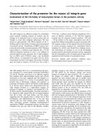
designed for soft tissue tumours. Figure 1 illustrates a MR-
only workflow and a more conventional CT-based work-
flow. In the MR-based workflow, the target definition, the
treatment planning, and patient positioning at treatment
delivery, are performed with MR aid only. The patient
positioning utilize a transport trolley to move the patient
from the imaging in the MR to the treatment table. A very
robust fixation of the patient provides control over the
relation among the coordinate systems in the patient, in
the MR, and in the treatment room. However, the trans-
port does introduce uncertainties, which must be
accounted for in an evaluation of the workflow and the
resulting geometric uncertainties.
An alternative workflow could be to plan on MR material
followed by positioning based on fiducial markers. This
intermediate workflow requires that the internal markers
are visible on the MR images and that the apparent marker
positions are correct. Parker et al. [14] shows that internal
markers appear clearly on gradient echo sequences, while
more difficulty to identify on T2-weighted turbo spin echo
sequences. The visibility of the markers was increased
when the TE time was reduced, giving higher signal but
compromising the T2-weighted contrast. Verified robust
imaging of fiducial markers in MR would enable also this
workflow. In the present study, this intermediate work-
flow will not be explicitly handled.
The purpose of this study is to investigate if a MR-only
radiotherapy workflow, in accordance with figure 1b, has
the potential to improve the spatial accuracy compared to
the more conventional CT-based workflow (figure 1a).
The estimations of the uncertainties in the different work-
flows are based on both a literature review and the results
of our own experiments.
Methods
In order to assess the total spatial uncertainties in the two
workflows, shown in figure 1, the workflow processes
were broken down into independent sub processes. Both
workflows contain two main steps where uncertainties
can be introduced, target definition for treatment plan-
ning and patient positioning at treatment delivery. Our
tools in the uncertainty analysis have been literature
reviews, and when necessary own experiments. The own
experiments concern positioning with MRI, and are
described in the section about MR guided delivery.
An open-bore MRI scanner (Siemens Espree, 1.5T) was
used for the MR imaging of the patients in connection
radiotherapy. For prostate patients, a T2-weighted SPACE
sequence (Siemens), which is a 3D turbo spin-echo
sequence with varying flip angle on the refocusing pulses,
was used. The slice thickness was 1.7 mm, typical pixel-
size was 1.0 × 1.0 mm
2
, and the bandwidth was 592 Hz
per pixel. Distortions caused by gradient non-linearity
were corrected with an algorithm based on spherical har-
monic expansion of the fields generated by the gradient
coils [15]. The 3D correction algorithm including repre-
sentation of the coils was delivered by Siemens as a stand-
ard clinical tool integrated in the scanner software (VB15).
The scanner was set in an isocentric mode, which moves
the table prior to the acquisition of each sequence, to
place the MR isocenter in the centre of the volume of
interest.
The total spatial uncertainty consists of both a random
part, varying in direction and magnitude from fraction to
fraction, and a systematic part, which is invariant over the
treatment period. The systematic and random uncertainty
should be given different weight in the formation of mar-
gins between the CTV and the PTV. In the present work we
used the weight factor 2.5 for the systematic errors and 0.7
for random errors as proposed by van Herk et. al. [16,17].
The PTV margin is hence expressed as
where Σ is the systematic and
σ
is the random spatial
uncertainty. The presented uncertainties are throughout
this paper presented in units of one standard deviation
(1SD), thus inherently assuming normal distributed data.
Uncertainty in target definition
The total uncertainty in the target definition can be bro-
ken down to three subparts: uncertainty in prostate delin-
eation (MR-based on both workflows), spatial distortion
in MR images that can be scanner related and patient
m
PTV
=∑+25 07
s
(1)
Overview of the two workflows analyzed in the present studyFigure 1
Overview of the two workflows analyzed in the
present study. (a) A widely used workflow utilizing regis-
tration between MR and CT images in order to transfer the
delineated prostate volume (GTV/CTV) from the MR study
to the CT study. The CT study is used for treatment planning
and to generate DRR's for patient position. Typically, fiducial
markers are used. (b) The workflow is entirely based on MR,
both for planning and positioning.
Radiation Oncology 2009, 4:54 />Page 3 of 9
(page number not for citation purposes)
induced, and for the CT-based workflow: uncertainty in
registration between CT and MR images.
Uncertainty in prostate delineation
Rasch et al [18] has from a study with 18 patient analysed
by 3 physicians reported an uncertainty, in the prostate
delineation on axial MR study, of 2 mm at the base of
seminal vesicles and up 2.8 mm in the prostate apex. The
uncertainty in the head-feat (HF) direction was 2.5 mm
with a slice thickness of 5-6 mm for the axial MR images.
In a later study involving 7 physicians analysing 10
patients Smith et al. [19] reported a radial uncertainty of
0.6 - 1.6 mm for the delineation of the prostate where the
larger value is for the apex. The inter-observer uncertainty
in the length (HF direction) of the prostate was 3.4 mm,
and the intra-observer variation was 2.6 mm; the slice
thickness was 2.5 mm.
In summary, the literature review indicates a prostate
delineation uncertainty of 1.8 mm in the right-left (RL)
and anterior-posterior (AP) directions and 2.8 mm in the
HF direction.
Geometrical Distortions in MR
Geometrical distortions in MR images are a well known
phenomena [20-22]. In modern MR scanners, gradient
non-linearity is the main cause of image distortions [20],
dominating over the effect of static field inhomogenity.
The distortions introduced by the gradient non-linearities
are increasing with the distance from the MR isocenter
[20,23] Without correction, the geometrical distortions in
modern MR scanners can cause deviations between phys-
ical and imaged distances of up to 20% in extreme situa-
tions. However, there are methods for distortion
correction which reduces the errors significantly. It is pos-
sible to use a specially designed geometry phantom to
characterize and correct the distortions for a specific scan-
ner [22,24]. In the present work, a gradient coil specific
distortion correction algorithm was applied. Even though
this device specific corrections only correct for intrinsic
gradient non-linearity connected to a specific type of scan-
ner/gradient coil, it has been shown that this kind of cor-
rection yields a spatial accuracy better than 2% [23,25],
which is sufficient when region of interest in the patient is
close to the MR isocenter. Patient anatomy, e.g. air pockets
in the rectal cavity, can generate susceptibility-generated
field changes up to ± 10 ppm [26]. With a bandwidth of
592 Hz per pixel this corresponds to distortions up to
approximately 1 pixel for a 1.5T scanner. Thus, magnetic
susceptibility related distortions are a minor effect for the
sequence used.
In summary, for a prostate with radius of 2.5 cm the geo-
metrical distortions can cause errors of up to 0.5 mm,
which corresponds to a standard deviation of around 0.2
mm. This uncertainty is approximately equal in all direc-
tions provided that a 3D correction algorithm is used.
Registration uncertainties - MR/CT
The workflow in figure 1a involves a registration between
a CT and MR study. Errors in this registration directly
affect the spatial accuracy of the target definition. Registra-
tions between MR and CT for prostate patients can be per-
formed based on fiducial markers [14]. The trend is,
however, to use mutual information (MI) registration
based directly on the patient anatomy [27,28]. The pros-
tate position relative other anatomical structures is not fix,
therefore the registration should ideally be based on the
prostate with just a small margin. However, this has been
reported problematic because of too limited morphologi-
cal information content in the CT representation of the
prostate [29,30]. A few studies have been performed eval-
uating the accuracy and precision of MI registration for CT
and MR studies of the prostate; the registration uncer-
tainty has been reported to be around 2 mm [29,31]. Rob-
erson et al. [31] reported that registration results depend
on the starting point for a specific MI optimization soft-
ware. The mean difference between different stating
points was up to 1 mm in the RL direction. The corre-
sponding number for MR-MR registration was 0.4 mm in
the HF direction which could indicate that the mutual
information maximum is more distinct for MR-MR regis-
tration compared to CT-MR registration.
In summary, the registration uncertainty for a CT - MR reg-
istration for a prostate case was estimated to be 2 mm
based on current reports in the scientific literature.
Uncertainty in patient positioning
The patient positioning at treatment, with the develop-
ment of image guided radiotherapy, been in focus the
recent years. For prostate cancer patients the improve-
ments in spatial treatment accuracy has been considera-
ble. Both the CT and the MR-based workflows, shown in
figure 1, rely on imaging before each fraction. Intra-frac-
tion motion of the prostate is therefore an issue for both
workflows.
Intra-fraction prostate motion
In a large investigation by Kotte et al [32] intra fraction
motion larger than 2 mm was observed during 66% of the
fractions, this number is roughly in agreement with the
results presented in other studies [33,34]. However,
reduction of the rectal filling has been showed to be of
great importance to achieve a stable prostate position
[33,35]; an uncertainty of 2 mm is therefore realistic for a
5-7 min treatment when patients are instructed to empty
rectum prior to treatment. The position uncertainty due to
prostate motion is most pronounced in the AP and HF
directions [32,36].
Radiation Oncology 2009, 4:54 />Page 4 of 9
(page number not for citation purposes)
In summary, the overall uncertainty for the prostate posi-
tion was estimated to 2 mm, which broken down in the
orthogonal directions corresponds to: 1.4 mm in AP and
HF, and 0.4 mm in RL.
Uncertainty with fiducial markers
There are numerous studies on the accuracy of patient
positioning using fiducial markers and portal or flat
screen kV images. Several different sources of uncertainty
need to be considered in order to correctly estimate the
overall accuracy of the workflow. Random positioning
errors are partly due to uncertainty in the registration
between the reference image and the portal/kV flat screen
image. Literature indicates that a manual registration typ-
ically results in uncertainty of around 0.7 mm in the HF
and RL direction, and 1.4 mm in the AP direction [37,38].
An investigation by Nichol et al [39] indicates that a sys-
tematic deformation of the prostate during radiotherapy
leads to drift in the relation between the centre of mass for
the markers and centre of mass for the contoured prostate.
This uncertainty is in the order of 1 mm, which is roughly
in agreement with other reports [40,41]. It should be
noted that deformation of the prostate is in many respects
equivalent to marker migration within the prostate. These
two effects are therefore not separated in the present work.
Prostate deformation and marker migration are resulting
in a systematic uncertainty in the patient position.
The uncertainty of clinical imaging systems are in the
order of 1 mm, accounting for limitations in resolution,
isocenter position and mechanical instability. Paulsen et
al [34] observed a systematic discrepancy of almost 1 mm
when comparing 2 different imaging modalities at 2 dif-
ferent accelerators. Kotte et al. [32] detected that the sag of
the gantry caused a systematic imaging deviations of
almost 1 mm in the HF direction when the gantry was in
0 degree position compared to 180 degree position.
In summary, it is estimated that the uncertainty in the day
to day registrations between reference image and the por-
tal image is 0.7 mm in RL and HF direction and 1.4 mm
in AP direction. The estimated uncertainty for the marker
position in the prostate is 1 mm in all directions, and the
estimated total uncertainty for the imaging systems is 1
mm in all directions.
MR guided treatment delivery
The MR positioning approach is novel; we therefore
describe the principals in detail below, as well as the
experiments performed to estimate the uncertainties con-
nected to the method.
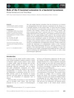
Figure 2 shows the hardware configuration. The patient is
transported between the MR scanner and the treatment
unit on a MR compatible trolley (Miyabi, TRUMPF). The
patient is fixated on a shell, with a double vacuum system
(BodyFIX, Medical Intelligence an Elekta company),
which can be slid from the trolley to the treatment or MR
table after docking. The shell has fixed positions both at
the MR and the treatment table, which enables absolute
coordinate transformation between MR coordinates and
treatment coordinates. The treatment table is a Siemens
550 TxT equipped with a modified TT-D table-top com-
patible with the Miyabi transport solution. The daily treat-
ment table coordinates are calculated as the absolute table
coordinates from the treatment planning corrected for
daily variations in patient and prostate position. The daily
correction is calculated based on a sub-volume-based
rigid mutual information registration between the refer-
ence MR images used at treatment planning and daily
positioning MR images. The same SPACE sequence was
used both for treatment planning and for daily position-
ing. Calibration of the system, i.e. determination of the
absolute coordinate transformation vector, is an obvious
source for systematic uncertainty, while mechanical insta-
bilities in the mounting mechanism at the MR and treat-
ment table together with image distortion, image
registration errors and patient movement during transport
mainly result in uncertainty of random nature.
Uncertainty in calibration vector determination
The calibration vector is the relation between the coordi-
nate for a specific point, in the MR coordinate system and
the treatment table coordinates that brings the same point
to the treatment isocenter. The calibration vector was
determined using a phantom which is sketched in figure
3. The centre point of the phantom is clearly visible on
MR, CT, portal images and can also be positioned using
lasers. We placed the phantom at various positions on the
Miyabi shell and carefully determined the position of the
centre point in both the MR coordinate system using MR
images, and the treatment coordinate system using cali-
brated lasers. The calibration vector was calculated, for
each phantom position on the Miyabi shell, as the differ-
ence between the MR coordinates and the treatment table
coordinates for the central point in the phantom. The idea
with repeated measurements was to assess the precision of
the vector determination taking intrinsic inhomogeneities
in the magnetic field and position dependent distortions
into account. In total 16 independent determinations of
the calibration vector was performed, for different phan-
tom positions on the Miyabi shell. The measurements
were performed with the phantom centre positioned at ±
25 mm in the AP direction, and ± 60 mm in the RL direc-
tion and at 4 different positions along the HF direction
with a total span of 450 mm. The scanning of the phan-
tom was performed in isocentric mode.
Weight correction
The calibration vector needs to be corrected based on the
patient's weight to account for the treatment table sag-
Radiation Oncology 2009, 4:54 />Page 5 of 9
(page number not for citation purposes)
ging. The magnitude of the sagging was investigated using
a set of 15 kg bricks which were distributed to approxi-
mate the weight distribution of a typical patient. We var-
ied the total load and the weight distribution on the table
top, to simulate patient weight from 0 to 105 kg, and
patient height from approximately 150 cm to 190 cm.
Geometrical distortions
The prostate is typically located on the patient's central
line and with the Miyabi shell together with the BodyFIX
vacuum pillow the height of the prostate for the typical
patient will be very close to the isocenter. The internal MR
laser is used to position the patient in the HF direction
before imaging, thus the prostate will be close to the iso-
center also in the HF direction. If the prostate centre is
within a sphere of 5 cm around the MR isocenter and the
maximum spatial distortion is 2% then the maximum
error will be approximately 1 mm, i.e. a standard devia-
tion around 0.5 mm. The geometrical distortions system-
atically affect the entire treatment through the reference
images, and do in addition contribute to random errors at
each fraction.
Patient movement
Significant patient movements during the time interval
from the imaging to the treatment are deemed highly
unlikely when using the double vacuum immobilization
device. There is however a risk for prostate movements
within the body during this time interval as discussed
above (see section about intra-fraction prostate move-
ment)
Position reproducibility
The reproducibility of the Miyabi shell position on the MR
and treatment table were investigated through measure-
ment of the maximum shell displacement under direct
force in different directions
Registration uncertainties MR/MR
The registration accuracy with mutual information algo-
rithms has been discussed above in the section about
uncertainty in target definition. Based on the high soft tis-
sue contrast in the MR images and the similar information
content in the reference and positioning image it was
assumed that the accuracy is limited by the size of the vox-
els. A voxel size of 1.0 × 1.0 × 2.5 mm
3
gives a registration
Schematic overview of the hardware configuration for the MR positioning of patientsFigure 2
Schematic overview of the hardware configuration for the MR positioning of patients. There is a direct connection
between the MR room and treatment room, which makes patient transport quick and simple. In parallel with the patient trans-
port the treatment couch coordinates are calculated using dedicated image registration software, the transport in it self does
therefore not prolong the procedure.
Radiation Oncology 2009, 4:54 />Page 6 of 9
(page number not for citation purposes)
uncertainty of 0.5, 0.5, and 1.25 mm in the RL, AP and HF
directions respectively.
Results
Uncertainties associated with MR transport
Calibration vector
The calibration vector relates the coordinate system in the
MR scanner with the treatment table coordinate system.
The estimated uncertainty for the calibration vector, based
on the 16 independent measurements, was 0.5 mm, 0.4
mm resp. 0.8 mm in the RL, HF and AP directions. The
mean value of the 16 observations is connected to a sys-
tematic uncertainty of 0.1 to 0.2 mm.
Correction for weight
The calibration vector was measured without load. There-
fore there is a need to correct for the sagging of the treat-
ment table under the weight of the patient. We found that
the sagging of the treatment table could be modelled as a
linear function of the patient weight (w) and the longitu-
dinal coordinate for the prostate (l) in the MR coordinate
system, according to:
where the units are kg and mm respectively.
For simulated patients in the weight interval between 60
and 110 kg with their prostate located approximately 700-
900 mm from the top of the skull, residual errors of max-
imum 1.2 mm was observed in the AP direction (figure 4),
and 0.4 mm in the HF direction. In general the residual
errors were small and the standard deviation of this sys-
tematic uncertainty was estimated to 0.6 mm in the AP
direction, 0.2 mm in the HF direction, and neglectable in
the RL direction.
Position reproducibility
Under direct force it was possible to displace the Miyabi
shell slightly below 1 mm in the HF direction; this maxi-
mum displacement corresponds to an uncertainty under
normal distribution assumption of around 0.5 mm. It was
not possible to measure any positioning inaccuracies in
the RL and AP directions. The uncertainty in the HF direc-
tion results in systematic uncertainties in the imaging for
the treatment planning with a magnitude of 0.5 mm, and
does in addition result in fraction to fraction positioning
uncertainties of 0.7 mm (both MR and treatment table
docking).
Comparison with established technique
Table 1 summarizes results from the literature review in
section 3 and results presented in section 4. The total esti-
mated positioning uncertainty for a CT-based workflow,
illustrated in figure 1a, is substantially larger than the esti-
mated uncertainty using the MR-based workflow (figure
1b). The clinical implication of spatial uncertainties is the
use of margins, dependent on both the random and sys-
tematic part. In the present work we use the model
described through equation (1). The CT-based workflow
should according to equation (1) be associated with the
following margins: RL - 8.1 mm, AP - 8.7 mm, and HF -
10.7 mm. The corresponding margin for the MR-based
workflow should be: RL - 5.3 mm, AP - 6.1 mm, and HF -
8.7 mm.
d
Z
wl=− −0 000178 1178 6.**(.)
(2)
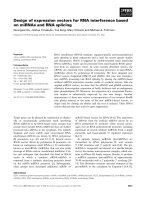
Calibration phantomFigure 3
Calibration phantom. The phantom which was used for
coordinate calibration is 15 × 15 × 15 cm3 and filled with
water. The central point is defined with lead bullet of 1 mm
diameter which is fasten with 6 thin plexi rods creating a 3D
hair cross.
Sagging of treatment tableFigure 4
Sagging of treatment table. Modelled table sagging, the
lines, is compared with observed sag, the points, for different
simulated patient weights and prostate positions. The param-
eter "Long" describes the distance from the head end of the
Miyabi shell to the prostate.
Radiation Oncology 2009, 4:54 />Page 7 of 9
(page number not for citation purposes)
Table 1: Estimated positioning uncertainties CT resp. MR based treatment procedure
CT based workflow MR based workflow
CT/MR-systematic CT/MR-Random MR-systematic MR-random
Contributing
factor
ΣRL mm ΣAP mm ΣHF mm σRL Mm σAP mm σgHF mm ΣRL mm ΣAP mm ΣHF mm σRL mm σAP mm σHF mm
Prostate delineation 1.8 1.8 2.8 1.8 1.8 2.8
Geometrical
distortions
0.2 0.2 0.2 0.2 0.2 0.2
MR to CT
registration
2 2 2
Total treatment
planning
uncertainty
2.7 2.7 3.4 1.8 1.8 2.8
Intra-fraction motion 0.4 1.4 1.4 0.4 1.4 1.4
CT to X-ray
registration
0.7 0.7 1.4
Fidutial marker
uncertainty
1.0 1.0 1.0
X-ray Imaging
uncertainty
1.0 1.0 1.0
MR Imaging
uncertainty/
distortion
0.5 0.5 0.5 0.5 0.5 0.5
MR to MR
registration
0.5 0.5 1.25
Calibration vector
determination
0.1 0.2 0.1
Weight correction 0.6 0.2
Docking mechanism 0.5 0.7
Total Set-up
uncertainty
1.4 1.4 1.4 0.8 1.6 2.0 0.5 0.8 0.7 0.8 1.6 2.1
Total uncertainty 3.0 3.0 3.7 0.8 1.6 2.0 1.9 2.0 2.9 0.8 1.6 2.1
Radiation Oncology 2009, 4:54 />Page 8 of 9
(page number not for citation purposes)
Discussion
Through this literature review together with our analysis
of the positioning procedure with MR, we claim that the
MR-only treatment workflow, shown in figure 1b, allows
for significantly smaller PTV margins than the CT-based
workflow (figure 1a). This conclusion has been reached
through estimations of the uncertainty for each sub proc-
ess in the treatment chain and sum-up's of the total spatial
uncertainty assuming that the errors from the sub proc-
esses are uncorrelated. This method yields results compa-
rable to other studies, for example, the resulting margins
for the positioning using CT-based workflow and gold
markers are comparable with the results presented by Bel-
tran et al. [42]. Excluding the uncertainty in the delinea-
tion of the prostate both Beltran et al. and the present
study estimate the proper margins to between 4 mm and
5 mm in all directions. The contributions from different
sources of uncertainty do however differ.
The reduced uncertainty does not necessarily mean that
MR-only is the optimal workflow as other aspects also
needs to be considered. It is not feasible to introduce a
positioning method which requires considerably more
patient time for all the 30-40 fractions than what are
standard at many departments. However, the importance
of occupation time per treatment would be reduced if the
hypo-fractionation of prostate treatments becomes clini-
cal standard.
The delineation uncertainty is dominating the systematic
overall uncertainty also for the MR only workflow. It is
clear that more effort needs to be spent on reducing uncer-
tainty in the target delineation procedure.
In the present study we have used a generic algorithm for
3D distortions correction provided as a standard routine
in the VB15 package delivered by Siemens. The accuracy of
this correction was validated using a Philips PIQT phan-
tom, through comparison with CT and through direct dis-
tance measurements in the images. The results were in
agreement with the results reported by Krager et al. [23]. It
can be expected that the accuracy of generic distortion cor-
rection algorithms may vary between individual scanners,
it is thus important to validate the geometrical accuracy
for each MR-scanner before any clinical implementation.
Equally important is verification of the site specific regis-
tration accuracy, which can differ depending of algorithm,
region of interest, and clinical implementation. The
uncertainty quantification presented in Table 1 are repre-
sentative for the described methodology, but should be
verified locally.
Registrations between MR and CT, and MR to MR, were in
the present study performed using a MI based method. An
alternative workflow uses the internal gold markers as ref-
erence points in a landmark based registration. This regis-
tration method was not included in the present study for
several reasons. -The markers are not clearly visible with
the T2 weighted 3D sequence that is we use for target
delineation. -Introduction of a dedicated sequence for vis-
ualization of the markers gives a systematic spatial uncer-
tainty because of prostate movement between the
sequences. -Use of a multi-echo sequence to acquire both
T2 weighted images for delineation and proton density
weighted images for visualization of the makers compro-
mise the quality of the images used for delineation com-
pared to present 3D sequence. -Finally, there is still a need
for an in-depth investigation of the spatial uncertainties in
the apparent marker position in the MR images, specifi-
cally, with respect to variations in frequency encoding
direction, bandwidth, slice encoding method, and marker
shape and orientation relative the main magnetic field.
Conclusion
It was shown that, from a spatial uncertainty point of
view, the MR-only prostate treatment workflow is to be
preferred in front of a MR/CT-based procedure. The sys-
tematic uncertainties introduced by the MR/CT-registra-
tion are affecting the entire treatment but are avoided with
the MR-based workflow, while the random uncertainties
from fraction to fraction are approximately the same as for
the MR/CT workflow.
Competing interests
The authors declare that they have no competing interests.
Authors' contributions
TN Participated in the design of the study participated in
the literature review and drafted the manuscript. MN Par-
ticipated in the design of the study and performed the
experimental work
MGK Participated in the design of the study and in the lit-
erature review. MK Participated in the design of the study
and in the literature review. All authors read and approved
the final manuscript
Acknowledgements
We thank Cenneth Forsmark for the construction of the equipment, Mag-
nus Karlsson (Siemens Healthcare, Sweden) for discussions and comments,
and the Swedish Cancer Society and the Cancer Research Foundation North
Sweden for financial support.
References
1. Hricak H: MR imaging and MR spectroscopic imaging in the
pre-treatment evaluation of prostate cancer. Br J Radiol 2005,
78(Spec No 2):S103-11.
2. Hawighorst H, Debus J, Schreiber W, Knopp MV, Engenhart-Cabillic
R, Essig M, Brix G, van Kaick G: Contrast-enhanced magnetiza-
tion transfer imaging: improvement of brain tumor conspi-
cuity and delineation for radiosurgical target volume
definition. Radiother Oncol 1997, 43(3):261-7.
3. Prabhakar R, Haresh KP, Ganesh T, Joshi RC, Julka PK, Rath GK:
Comparison of computed tomography and magnetic reso-
nance based target volume in brain tumors. J Cancer Res Ther
2007, 3(2):121-3.
Radiation Oncology 2009, 4:54 />Page 9 of 9
(page number not for citation purposes)
4. Rasch C, Steenbakkers R, van Herk M: Target definition in pros-
tate, head, and neck. Semin Radiat Oncol 2005, 15(3):136-45.
5. Krempien RC, Daeuber S, Hensley FW, Wannenmacher M, Harms
W: Image fusion of CT and MRI data enables improved tar-
get volume definition in 3D-brachytherapy treatment plan-
ning. Brachytherapy 2003, 2(3):164-71.
6. Pasquier D, Betrouni N, Vermandel M, Lacornerie T, Lartigau E,
Rousseau J: MRI alone simulation for conformal radiation
therapy of prostate cancer: technical aspects. Conf Proc IEEE
Eng Med Biol Soc 2006, 1:160-3.
7. Chen L, Nguyen TB, Jones E, Chen Z, Luo W, Wang L, Price RA Jr,
Pollack A, Ma CM: Magnetic resonance-based treatment plan-
ning for prostate intensity-modulated radiotherapy: crea-
tion of digitally reconstructed radiographs. Int J Radiat Oncol
Biol Phys 2007, 68(3):903-11.
8. Chen L, Price RA Jr, Nguyen TB, Wang L, Li JS, Qin L, Ding M, Palacio E,
Ma CM, Pollack A: Dosimetric evaluation of MRI-based treatment
planning for prostate cancer. Phys Med Biol 2004, 49(22):5157-70.
9. Chen L, Price RA Jr, Wang L, Li J, Qin L, McNeeley S, Ma CM, Freed-
man GM, Pollack A: MRI-based treatment planning for radio-
therapy: dosimetric verification for prostate IMRT. Int J Radiat
Oncol Biol Phys 2004, 60(2):636-47.
10. Chen Z, Ma CM, Paskalev K, Li J, Yang J, Richardson T, Palacio L, Xu
X, Chen L: Investigation of MR image distortion for radiother-
apy treatment planning of prostate cancer. Phys Med Biol 2006,
51(6):1393-403.
11. Raaijmakers AJ, Raaymakers BW, Meer S van der, Lagendijk JJ: Integrating
a MRI scanner with a 6 MV radiotherapy accelerator: impact of
the surface orientation on the entrance and exit dose due to the
transverse magnetic field. Phys Med Biol 2007, 52(4):929-39.
12. Lagendijk JJ, Raaymakers BW, Raaijmakers AJ, Overweg J, Brown KJ,
Kerkhof EM, Put RW van der, Hardemark B, van Vulpen M, Heide UA
van der: MRI/linac integration. Radiother Oncol 2008, 86(1):25-9.
13. Karlsson M, Karlsson MG, Nyholm T, Amies C, Zackrisson B: Dedi-
cated MR in the Radiotherapy clinic. Int J Radiat Oncol Biol Phys
2009, 74(2):644-51.
14. Parker CC, Damyanovich A, Haycocks T, Haider M, Bayley A, Catton
CN: Magnetic resonance imaging in the radiation treatment
planning of localized prostate cancer using intra-prostatic
fiducial markers for computed tomography co-registration.
Radiother Oncol 2003, 66(2):217-24.
15. Janke A, Zhao H, Cowin GJ, Galloway GJ, Doddrell DM: Use of
spherical harmonic deconvolution methods to compensate
for nonlinear gradient effects on MRI images. Magn Reson Med
2004, 52(1):115-22.
16. van Herk M, Remeijer P, Rasch C, Lebesque JV: The probability of
correct target dosage: dose-population histograms for deriv-
ing treatment margins in radiotherapy. Int J Radiat Oncol Biol
Phys 2000, 47(4):1121-35.
17. van Herk M: Errors and margins in radiotherapy. Semin Radiat
Oncol 2004, 14(1):52-64.
18. Rasch C, Barillot I, Remeijer P, Touw A, van Herk M, Lebesque JV:
Definition of the prostate in CT and MRI: a multi-observer
study. Int J Radiat Oncol Biol Phys 1999, 43(1):57-66.
19. Smith WL, Lewis C, Bauman G, Rodrigues G, D'Souza D, Ash R, Ho
D, Venkatesan V, Downey D, Fenster A: Prostate volume con-
touring: a 3D analysis of segmentation using 3DTRUS, CT,
and MR. Int J Radiat Oncol Biol Phys 2007, 67(4):1238-47.
20. Wang D, Strugnell W, Cowin G, Doddrell DM, Slaughter R: Geo-
metric distortion in clinical MRI systems Part I: evaluation
using a 3D phantom. Magn Reson Imaging 2004, 22(9):1211-21.
21. Wang D, Strugnell W, Cowin G, Doddrell DM, Slaughter R: Geo-
metric distortion in clinical MRI systems Part II: correction
using a 3D phantom. Magn Reson Imaging 2004, 22(9):1223-32.
22. Wang D, Doddrell DM, Cowin G: A novel phantom and method
for comprehensive 3-dimensional measurement and correc-
tion of geometric distortion in magnetic resonance imaging.
Magn Reson Imaging 2004, 22(4):529-42.
23. Karger CP, Hoss A, Bendl R, Canda V, Schad L: Accuracy of device-
specific 2D and 3D image distortion correction algorithms
for magnetic resonance imaging of the head provided by a
manufacturer. Phys Med Biol 2006, 51(12):N253-61.
24. Doran SJ, Charles-Edwards L, Reinsberg SA, Leach MO: A complete
distortion correction for MR images: I. Gradient warp cor-
rection. Phys Med Biol 2005, 50(7):1343-61.
25. Jovicich J, Czanner S, Greve D, Haley E, Kouwe A van der, Gollub R,
Kennedy D, Schmitt F, Brown G, Macfall J, Fischl B, Dale A: Reliabil-
ity in multi-site structural MRI studies: effects of gradient
non-linearity correction on phantom and human data. Neu-
roimage 2006, 30(2):436-43.
26. Schenck JF: The role of magnetic susceptibility in magnetic
resonance imaging: MRI magnetic compatibility of the first
and second kinds. Med Phys 1996, 23(6):815-50.
27. Maes F, Collignon A, Vandermeulen D, Marchal G, Suetens P: Multi-
modality image registration by maximization of mutual
information. IEEE Trans Med Imaging 1997, 16(2):187-98.
28. Wells WM, Viola P, Atsumi H, Nakajima S, Kikinis R: Multi-modal
volume registration by maximization of mutual information.
Med Image Anal 1996, 1(1):35-51.
29. McLaughlin PW, Narayana V, Kessler M, McShan D, Troyer S, Marsh
L, Hixson G, Roberson PL: The use of mutual information in
registration of CT and MRI datasets post permanent
implant. Brachytherapy 2004, 3(2):61-70.
30. Vidakovic S, Jans HS, Alexander A, Sloboda RS: Post-implant com-
puted tomography-magnetic resonance prostate image reg-
istration using feature line parallelization and normalized
mutual information. J Appl Clin Med Phys 2007, 8(1):21-32.
31. Roberson PL, McLaughlin PW, Narayana V, Troyer S, Hixson GV,
Kessler ML: Use and uncertainties of mutual information for
computed tomography/magnetic resonance (CT/MR) regis-
tration post permanent implant of the prostate. Med Phys
2005, 32(2):473-82.
32. Kotte AN, Hofman P, Lagendijk JJ, van Vulpen M, Heide UA van der:
Intrafraction motion of the prostate during external-beam
radiation therapy: analysis of 427 patients with implanted
fiducial markers.
Int J Radiat Oncol Biol Phys 2007, 69(2):419-25.
33. Ghilezan MJ, Jaffray DA, Siewerdsen JH, Van Herk M, Shetty A, Sharpe
MB, Zafar Jafri S, Vicini FA, Matter RC, Brabbins DS, Martinez AA:
Prostate gland motion assessed with cine-magnetic reso-
nance imaging (cine-MRI). Int J Radiat Oncol Biol Phys 2005,
62(2):406-17.
34. Poulsen PR, Muren LP, Hoyer M: Residual set-up errors and mar-
gins in on-line image-guided prostate localization in radio-
therapy. Radiother Oncol 2007, 85(2):201-6.
35. Fiorino C, Di Muzio N, Broggi S, Cozzarini C, Maggiulli E, Alongi F,
Valdagni R, Fazio F, Calandrino R: Evidence of Limited Motion of
the Prostate by Carefully Emptying the Rectum as Assessed
by Daily MVCT Image Guidance with Helical Tomotherapy.
Int J Radiat Oncol Biol Phys 2008, 1;71(2):611-7.
36. Britton KR, Takai Y, Mitsuya M, Nemoto K, Ogawa Y, Yamada S:
Evaluation of inter- and intrafraction organ motion during
intensity modulated radiation therapy (IMRT) for localized
prostate cancer measured by a newly developed on-board
image-guided system. Radiat Med 2005, 23(1):14-24.
37. Berthelet E, Truong PT, Zavgorodni S, Moravan V, Liu MC, Runkel J,
Bendorffe B, Sayers D: Consistency in electronic portal imaging
registration in prostate cancer radiation treatment verifica-
tion. Radiat Oncol 2006, 1:37.
38. Moseley DJ, White EA, Wiltshire KL, Rosewall T, Sharpe MB, Siew-
erdsen JH, Bissonnette JP, Gospodarowicz M, Warde P, Catton CN,
Jaffray DA: Comparison of localization performance with
implanted fiducial markers and cone-beam computed tom-
ography for on-line image-guided radiotherapy of the pros-
tate. Int J Radiat Oncol Biol Phys 2007, 67(3):942-53.
39. Nichol AM, Brock KK, Lockwood GA, Moseley DJ, Rosewall T,
Warde PR, Catton CN, Jaffray DA: A magnetic resonance imag-
ing study of prostate deformation relative to implanted gold
fiducial markers. Int J Radiat Oncol Biol Phys 2007, 67(1):48-56.
40. Poggi MM, Gant DA, Sewchand W, Warlick WB: Marker seed
migration in prostate localization. Int J Radiat Oncol Biol Phys
2003, 56(5):1248-51.
41. Kitamura K, Shirato H, Shimizu S, Shinohara N, Harabayashi T,
Shimizu T, Kodama Y, Endo H, Onimaru R, Nishioka S, Aoyama H,
Tsuchiya K, Miyasaka K: Registration accuracy and possible
migration of internal fiducial gold marker implanted in pros-
tate and liver treated with real-time tumor-tracking radia-
tion therapy (RTRT). Radiother Oncol 2002, 62(3):275-81.
42. Beltran C, Herman MG, Davis BJ: Planning target margin calcu-
lations for prostate radiotherapy based on intrafraction and
interfraction motion using four localization methods. Int J
Radiat Oncol Biol Phys 2008, 70(1):289-95.