Báo cáo khoa học: " Correction of patient positioning errors based on in-line cone beam CTs: clinical implementation and first experiences" pptx
Bạn đang xem bản rút gọn của tài liệu. Xem và tải ngay bản đầy đủ của tài liệu tại đây (1.05 MB, 9 trang )
BioMed Central
Page 1 of 9
(page number not for citation purposes)
Radiation Oncology
Open Access
Research
Correction of patient positioning errors based on in-line cone beam
CTs: clinical implementation and first experiences
Christoph Thilmann*
1,3
, Simeon Nill
2
, Thomas Tücking
2
, Angelika Höss
2
,
Bernd Hesse
2
, Lars Dietrich
2
, Rolf Bendl
2
, Bernhard Rhein
2
, Peter Häring
2
,
Christian Thieke
1,3
, Uwe Oelfke
2
, Juergen Debus
3
and Peter Huber
1
Address:
1
Dept. of Radiooncology, German Cancer Research Center, Heidelberg, Germany,
2
Dept. of Medical Physics, German Cancer Research
Center, Heidelberg, Germany and
3
Clinical Radiology, University of Heidelberg, Heidelberg, Germany
Email: Christoph Thilmann* - ; Simeon Nill - ; Thomas Tücking - ;
Angelika Höss - ; Bernd Hesse - ; Lars Dietrich - ; Rolf Bendl - ;
Bernhard Rhein - ; Peter Häring - ; Christian Thieke - ; ;
Juergen Debus - ; Peter Huber -
* Corresponding author
Abstract
Background: The purpose of the study was the clinical implementation of a kV cone beam CT (CBCT) for setup correction
in radiotherapy.
Patients and methods: For evaluation of the setup correction workflow, six tumor patients (lung cancer, sacral chordoma,
head-and-neck and paraspinal tumor, and two prostate cancer patients) were selected. All patients were treated with
fractionated stereotactic radiotherapy, five of them with intensity modulated radiotherapy (IMRT). For patient fixation, a scotch
cast body frame or a vacuum pillow, each in combination with a scotch cast head mask, were used. The imaging equipment,
consisting of an x-ray tube and a flat panel imager (FPI), was attached to a Siemens linear accelerator according to the in-line
approach, i.e. with the imaging beam mounted opposite to the treatment beam sharing the same isocenter. For dose delivery,
the treatment beam has to traverse the FPI which is mounted in the accessory tray below the multi-leaf collimator. For each
patient, a predefined number of imaging projections over a range of at least 200 degrees were acquired. The fast reconstruction
of the 3D-CBCT dataset was done with an implementation of the Feldkamp-David-Kress (FDK) algorithm. For the registration
of the treatment planning CT with the acquired CBCT, an automatic mutual information matcher and manual matching was used.
Results and discussion: Bony landmarks were easily detected and the table shifts for correction of setup deviations could be
automatically calculated in all cases. The image quality was sufficient for a visual comparison of the desired target point with the
isocenter visible on the CBCT. Soft tissue contrast was problematic for the prostate of an obese patient, but good in the lung
tumor case. The detected maximum setup deviation was 3 mm for patients fixated with the body frame, and 6 mm for patients
positioned in the vacuum pillow. Using an action level of 2 mm translational error, a target point correction was carried out in
4 cases. The additional workload of the described workflow compared to a normal treatment fraction led to an extra time of
about 10–12 minutes, which can be further reduced by streamlining the different steps.
Conclusion: The cone beam CT attached to a LINAC allows the acquisition of a CT scan of the patient in treatment position
directly before treatment. Its image quality is sufficient for determining target point correction vectors. With the presented
workflow, a target point correction within a clinically reasonable time frame is possible. This increases the treatment precision,
and potentially the complex patient fixation techniques will become dispensable.
Published: 24 May 2006
Radiation Oncology 2006, 1:16 doi:10.1186/1748-717X-1-16
Received: 07 November 2005
Accepted: 24 May 2006
This article is available from: />© 2006 Christoph et al; licensee BioMed Central Ltd.
This is an Open Access article distributed under the terms of the Creative Commons Attribution License ( />),
which permits unrestricted use, distribution, and reproduction in any medium, provided the original work is properly cited.
Radiation Oncology 2006, 1:16 />Page 2 of 9
(page number not for citation purposes)
Introduction
A CT scan acquired for treatment planning usually repre-
sents only a single snapshot of the anatomical structures
in time and is gathered several days before treatment. The
shape and location of internal soft tissue structures at the
time of treatment may deviate considerably from the ini-
tial scan. This problem cannot be solved by further
improvements of external patient positioning like more
rigid fixation devices. Especially in high precision radio-
therapy, the daily position of the target needs to be con-
firmed before irradiation by a reliable imaging modality.
Different approaches are available for three-dimensional
image acquisition inside the radiation treatment room.
Megavoltage CT and kilovoltage CT (helical and cone
beam) has been tested so far [1-3]. Kilovoltage CT has
become the standard modality for soft tissue identifica-
tion and target definition in conformal radiation therapy.
A well established approach for in-room image acquisi-
tion is the use of a conventional CT scanner sharing the
same couch with the linear accelerator [4], e.g. the Sie-
mens PRIMATOM system (Siemens OCS, Concord, USA)
combining the linear accelerator Siemens Primus and the
CT scanner Siemens Emotion. The advantage of that sys-
tem obviously is that all components are separately estab-
lished for clinical application. The achievable high image
quality and the accuracy of the system allow a reasonable
handling of interfractional setup errors and organ motion.
However, besides the disadvantage of having two large
technical systems in a radiotherapy bunker, such systems
cannot detect intrafraction motion. Also the necessary
repositioning of the patient between the CT scan and the
irradiation adds time to the overall procedure.
Using an in-line imaging setup attached to the gantry of
the linear accelerator allows to overcome these disadvan-
tages. Such an equipment consisting of an x-ray tube and
a flat panel imager (FPI) attached to a linear accelerator
(LINAC) (Siemens OCS) is available in our institution.
The purpose of the present study was the clinical imple-
mentation of the kV cone beam CT (CBCT) and its appli-
cation for patient setup correction in radiotherapy (RT).
The paper focuses on the development of a reliable work-
flow from image acquisition to correction of interfraction
setup deviations. We will also discuss further improve-
ments and the potential clinical impact.
Patients and methods
Patients, image acquisition in treatment position
For evaluation of the setup correction workflow, six tumor
patients were selected. Two of them suffered from local-
ized prostate cancer, the remaining from lung cancer, sac-
ral chordoma, head and neck and paraspinal tumors. The
patient characteristics are summarized in table 1.
All patients were treated with fractionated stereotactic RT.
All except the lung cancer patient were treated with IMRT.
Every patient was treated in an individually customized
fixation device. Patients with prostate cancer and paraspi-
nal tumors were immobilized by a wrap-around body cast
and a head mask. For treatment of the thoracic and head-
and-neck-region, a vacuum pillow was used. Both extrac-
ranial fixation devices were complemented by a head
mask to eliminate head rotations which might translate
into movements of the spine. Both systems were embed-
ded in a stereotactic frame enabling stereotactic image cor-
relation [5].
Dose plans for both IMRT and conventional treatment
planning in 3D conformal technique (CRT) were calcu-
lated using the treatment planning system Voxelplan [6].
Inverse treatment planning for IMRT was carried out with
KonRad™ [7]. The dose delivery of the IMRT fields was car-
ried out in the step-and-shoot technique. Beam shaping
was calculated for a 6 MV LINAC fitted with a multi-leaf
collimator with 10 mm leaf width.
Table 1: Patient characteristics
Patient
number
diagnosis target volume treatment technique fixation
#1 lung cancer cT2cN0 right lower lobe primary tumor (boost) fractionated stereotactic
radiotherapy
vacuum pillow
#2 oropharyngeal cancer pT2cN0 primary and locoregional lymph
nodes
fractionated IMRT vacuum pillow and head mask
#3 prostate cancer T3c Gleason score 6
PSA 5.6
prostate and seminal vesicles fractionated IMRT stereotactic body cast and head
mask
#4 prostate cancer T2c Gleason score 7
PSA 12.0
prostate and seminal vesicles fractionated IMRT stereotactic body cast and head
mask
#5 unresectable chordoma lumbosacral spine fractionated IMRT stereotactic body cast and head
mask
#6 recurrence of soft tissue sarcoma lumbal spine and right m. psoas fractionated IMRT stereotactic body cast and head
mask
Radiation Oncology 2006, 1:16 />Page 3 of 9
(page number not for citation purposes)
In daily clinical routine we normally use the available in-
room CT scanner of the PRIMATOM to detect and, if nec-
essary, correct for interfractional setup errors. For the
study presented in this paper, we installed the in-line
imaging equipment onto the linear accelerator of the PRI-
MATOM system.
Imaging system and acquisition
The integrated imaging system presented in this paper
consists of a kV x-ray tube (Siemens "Optitop") and a flat
panel radiation image detector (FPI) from PerkinElmer
(XRD 1640) attached to the Primus LINAC following the
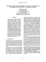
in-line approach. For this approach the diagnostic kV x-
ray tube is mounted at an angle of 180 degree with respect
to the therapeutic treatment beam (fig. 1). Both technical
components (x-ray tube and FPI) are attached to the linear
accelerator by in-house developed devices. The x-ray tube
position was chosen to have the same source-to-isocenter
distance (SID) as the treatment beam, i.e., SID = 100 cm.
The distance from the kV-source to the front plane of the
detector is approximately 140 cm. Therefore the central
axis of the kV-imaging beam is always aligned with the
central axis of the MV therapy beam. Another important
feature of the in-line geometry is that the FPI can take
images using the kV- and the MV-beam at the same time.
This enables the online validation of the delivered fluence
to the patient and the possibility to calculate the dose
actually delivered to the patient [8].
The impact of the panel on the dose distribution was eval-
uated carefully prior to the treatment of the patients. The
monitor units must be scaled by a factor of 1.18 to obtain
the same dose inside the patient as without the FPI in the
accessory holder. No impacts on the depth dose distribu-
Linear accelerator equipped with an x-Ray tube mounted at the opposite side of the MV-beam sourceFigure 1
Linear accelerator equipped with an x-Ray tube mounted at the opposite side of the MV-beam source. The flat panel detector
is attached right below the multi-leaf collimator. Single kV-images or cone beam CT sequences of patient in treatment position
can be acquired for image guide radiotherapy.
Radiation Oncology 2006, 1:16 />Page 4 of 9
(page number not for citation purposes)
tion, lateral profiles or dose to the patient's surface were
found.
The selected x-ray tube features a 40 kW-0.6 mm and an
80 kW-1 mm focal spot, 150 kVp nominal voltage and has
a 12 degree anode target angle. The imaging detector has
an active area of about 40.96 × 40.96 cm
2
, a spatial reso-
lution of 0.4 mm in each direction for a 1024 × 1024
bixel-matrix with 16 bit gray values. The detector uses a
Gd
2
O
2
S:Tb scintilator and the fastest readout time is
about 66 ms.
The imaging control system is located within the control
room of the linac next to the treatment console. Through
this control system, the user can select different imaging
modes like the acquisition of single x-ray pulses,
sequences of different x-ray pulses or fluoroscopy imaging
acquired on external trigger signals. For each x-ray pulse
the user can define values for the tube current (mA), the
pulse length (ms) and the high voltage value (kVp). These
parameters are then transferred to the x-ray hardware con-
trol system. Typical acquisition parameters for a projec-
tion image were 120 kVp, 20 ms and 50 mA. For 200
projections this leads to dose of 14 mGy at the isocenter
of a cylindrical water phantom with a diameter of 18 cm.
To acquire a cone beam CT, the gantry of the linear accel-
erator rotates around the patient in treatment position at
a fixed speed. An inclinometer attached to the linac's gan-
try generates a trigger signal for gantry angles with a fixed
angle increment. This signal finally generates the x-ray
pulse for one CT-image projection which is directly trans-
ferred from the detector to the reconstruction computer
for further image processing.
The raw images obtained from the detector are then cor-
rected for pixel based dark image offset and detector gain
structure as well as for corrupt pixels and x-ray field inho-
mogeneities. These corrections are performed with the
help of previously stored offset and gain correction
images. The offset images were acquired directly prior to
the patient images, while only one gain image was
acquired in the morning [9].
A geometrical calibration is necessary due to mechanical
flexibility of the x-ray tube holder and the FPI during gan-
try rotation. This is done using a cylindrical calibration
phantom with regularly placed bullets on a helical trajec-
tory at its periphery. The detailed calibration procedure is
described in the thesis of M. Ebert [10].
The processed images and the calibration data are trans-
ferred to an in-house developed reconstruction tool using
the standard Feldkamp-David-Kress (FDK) algorithm for
cone beam CT reconstruction [11]. The output is a 3D CT-
dataset with user specified voxel resolution. For all cases,
256 × 256 × 256 voxels with a resolution of 1.0 mm were
reconstructed except for the prostate cases where a voxel
resolution of 1.56 mm was chosen due to the larger field
of view. The reconstruction time for a cone beam data set
varies depending on the selected resolution and the
number of used projections. Typically it is between 1 and
3 minutes on a 3 GHz personal computer.
To reconstruct a complete 3D data set of a cone beam CT,
projections over a range of at least 200 degrees (180
degree + two times the fan beam angle)(Ref auf Ebert)
must be acquired. This procedure is called "short scan".
We used a spacing of one degree and therefore acquired
200 projections per patient.
Detection and correction of setup errors
The workflow schematically shown in figure 2 was used to
detect and correct for any misalignment of the target vol-
ume in the described clinical cases (fig. 2). The first steps
are the patient positioning, the image acquisition and the
reconstruction of the 3D data set as described in the pre-
vious section. The next step is the rigid registration of the
acquired cone beam CT with the diagnostic planning CT.
This is achieved by either manually selecting bony land-
marks or by using an automatic matching algorithm that
maximizes mutual information. The result of the mutual
information matching is determined by all grey values
and not restricted to the bones. The successful registration
of the two datasets is approved by a visual comparison of
clearly identifiable landmarks (e.g. bony structures)
within both image sets. With the information now availa-
ble, the dislocation of the tumor target volume can be cal-
culated. Thereby the target volume is treated as a rigid
body, i.e., its new position in space is determined by a
rigid transformation with 6 degrees of freedom (a 3-
dimensional spatial translation and the 3 Euler rotations
Schematic description of the workflow applied for automatic patient positioningFigure 2
Schematic description of the workflow applied for automatic patient positioning.
CBCT data
acquisition
3D image
reconstruction
mutual information
matching of CT for
planning and CBCT
visual validation of
automatic match and
calculated table shift
patient repositioning
if necessary
Radiation Oncology 2006, 1:16 />Page 5 of 9
(page number not for citation purposes)
around the axes through the isocenter). Deformations of
the target were not accounted for. Only the target transla-
tions could be used for the target positioning process, in
which the translation vector of the target is converted to a
respective shift of the treatment table. The rotational error
was documented, but could not be corrected for. The off-
set values between the original and the new table position
were automatically transferred to the treatment table and
the shift was then automatically executed under the super-
vision of the technician and a physician.
For the translations an action level of 2 mm for each axis
of the translation vector was defined. The threshold for
the rotation angles and the transversal shift vector were
derived from the applied safety margin to the CTV during
the planning process. Only if the offset components were
larger than the action level, the patient was shifted to the
new treatment position.
The residual error after the correction of the transversal
components is mainly given by the positioning precision
of the table which is +-0.5 mm. Additional intrafractional
variations also contribute to the remaining error, how-
ever, these were not analyzed in the present study.
Results and discussion
Matching and image quality
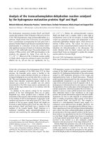
Figure 3 shows exemplary CT slices of the planning CT
and the CBCT for the lung, head-and-neck, prostate and
paraspinal cases. In all cases, the automatic matching
algorithm could register the CBCT to the planning CT. The
registration was verified by visual assessment of clearly
identifiable bony landmarks which showed an exact
match.
At the current stage of development, the overall image
quality and especially the soft tissue contrast of the CBCT
scans do not reach the standard of dedicated diagnostic
CT scans. The reduced contrast is partly due to scattered
photons. For larger patients the distance between the
object to image and the detector is reduced and therefore
the percentage of scattered photons compared to the pri-
mary photons is increased. This problem is inherent to the
cone-beam design, since collimating the photons cannot
be as strict as in fan-beam CT scanners. Truncation arti-
facts are deteriorating the image quality further, see e.g.
the outer body contour of patient 4 in fig. 3.
Correction of the target point
In all evaluated cases the threshold of 2 degree rotation
was not violated. The detected maximum setup deviation
was 3 mm for patients immobilized with the body frame,
and 6 mm for patients positioned on a vacuum pillow.
Due to the action level of 2 mm translation, a target point
correction was carried out in 4 cases (table 2). The addi-
tional workload of the described workflow compared to a
normal treatment fraction led on average to an extra time
of about 10–12 minutes (table 3).
Dealing with rotational errors
In this work, we implemented rigid matching (detecting
translational and rotational errors) and correction of tran-
lational errors only into the clinical workflow. In cases
where the rotations exceed the threshold, it might be help-
ful to temporarily losen the patient's fixation and reposi-
tion him with the observed deviation in mind (e.g.
advising him to lift one shoulder for a rotation along the
body axis). Then the workflow would start again with the
acquisition of a new 3D image data set. This would add
another 3–5 minutes to the workflow. Another approach
for better compensation of rotational errors would be not
only to shift the patient but also to modify the gantry, col-
limator and couch angle [12].
Prostate cancer
There is fairly strong evidence that at least patients with
localized prostate cancer with intermediate to high risk
benefit from higher than conventional prescribed total
dose values [13]. There is some evidence that 3D confor-
mal radiotherapy results in reduced late rectal toxicity and
acute anal toxicity compared with radiotherapy adminis-
tered with non-conformal treatment volumes [14]. Ghile-
zan et al. have demonstrated the potential benefit of
image guided radiotherapy (IGRT) for prostate cancer
[15]. They have found that the ideal maximum dose incre-
ment achievable with online IGRT is, on average, 13%
with respect to the dose-limiting organ of rectum. The the-
oretical gain of IGRT can only be achieved when organ
Table 2: Setup deviations evaluated with CBCT
Patient
number
latero-lateral shift ventro-dorsal shift cranio-caudal shift max. rotation target point correction image quality
#1 3.1 mm 0.1 mm 6.0 mm 0° yes good
#2 -0.6 mm 0.5 mm -0.7 mm 0.6° no good
#3 -0.7 mm -1.2 mm 2.3 mm 0.7° yes poor
#4 1.2 mm 3.6 mm 0.1 mm 1.1° yes sufficient
#5 0.3 mm 0.1 mm 0.1 mm 0° no sufficient
#6 -2.6 mm -1.7 mm -1.7 mm 1.5° yes sufficient
Radiation Oncology 2006, 1:16 />Page 6 of 9
(page number not for citation purposes)
Clinical examples of cone beam (right side) compared to diagnostic treatment planning CT (left side)Figure 3
Clinical examples of cone beam (right side) compared to diagnostic treatment planning CT (left side).
Patient 1: lung cancer
CT for treatment planning
Cone beam CT
Patient 2: oropharyngeal cancer
Patient 3: prostate cancer
Patient 4: soft tissue sarcoma
Radiation Oncology 2006, 1:16 />Page 7 of 9
(page number not for citation purposes)
motion/deformation can be visualized in a reasonable
image quality and extra time.
In a first step of registration, we gave preference to bony
landmarks of the pelvic region and calculated a target
shift. We verified the correct position of the prostate and
seminal vesicles after shifting the target point by visually
assessing the image data sets. In the presented cases, there
was a sufficient match (not more than 2 mm of deviation)
between the prostate visible on the CT for treatment plan-
ning and the actual cone beam CT. In both cases, the irra-
diation could be started as intended. The process of soft
tissue comparison is slightly hampered by the reduced
image quality of the cone beam CT compared to the diag-
nostic CT. If an additional shift of the prostate would have
been visible compared to the shift of bone structures, this
would have been corrected manually. The manual match
of soft tissue is a little elaborate due to the low contrast of
the CT slices. Nevertheless, the entire procedure can be
carried out within a reasonable time frame. The extra time
needed is in the range of 8–10 minutes for image acquisi-
tion and setup evaluation and is prolonged for additional
2–3 minutes if a setup correction is necessary. We are cur-
rently working on matching algorithms that will enable
the automatic correction of interfractional displacements
of the prostate itself. Here, an improved image quality is
necessary especially for obese patients.
Head-and-neck tumors
In the presented case, artifacts in the cone beam images
were visible close to the plane of the head-ring of the
patient fixation, where significant data loss occurred due
to attenuation, and in the plane of metallic implants. Nev-
ertheless, the image quality was sufficient to work out
bone structures in almost all CT slices. Since the soft tissue
of the target volume is entirely framed by bone structures,
the correlation of bones is sufficient for detection of setup
deviations which can be carried out for the entire data set.
The target volume for head-and-neck tumors regularly
includes the base of skull and extends to the upper tho-
racic aperture. The patients are fixated with a head mask
and a vacuum pillow. The cranial part inside the head
mask is very accurately repositioned during the whole
treatment course. However, the location of the lower
extracranial part shows more variations. The result is a
complex deformation of the target volume that cannot be
described by a simple translation and cannot be easily cor-
rected by shifting the target point without changing the
treatment plan [16]. In first approximation the transfor-
mation can be separated into a (small) translation of the
base of skull and a rotation. Prerequisite for this proce-
dure is that the isocenter is near the base of skull. Since
available treatment tables can only be rotated within the
table plane, only this rotation can be compensated. In the
presented case, neither a translation nor a rotation needed
to be corrected.
For high level adaptivity, the complex deformation of the
target in head-and-neck irradiation can not be ignored.
Changes of the patient's anatomy during the treatment
course like weight loss or tumor response are common
which require repeated treatment planning. Here, algo-
rithms for automatic deformation of images and struc-
tures and automatic adaption of dose distribution by
deformation of treatment fields and intensity maps are
desirable. First promising approaches were presented by
Mohan et al. [17] and Hansen et al.[18]
Lung cancer
Dose escalation seems to be a useful strategy in treating
non small cell lung cancer. A simple increase in the dose
by giving additional fractions is limited by the tolerance
doses of the surrounding tissue. The use of 3D-conformal
radiotherapy significantly reduces doses to the spinal
cord, heart and esophagus but does not improve lung
sparing [19]. Lung has been identified as the dose limiting
organ at risk in dose escalation trials [20]. Thus, dose esca-
lation should be combined with the reduction of treat-
ment volumes which implies a reduction of margins.
Optimal would be the elimination of interfraction and
intrafraction organ motion with the objective of minimiz-
ing the margins of the planning target volume. The cone
beam CT allows for detection and correction of target
Table 3: Mean time intervals needed for cone-beam CT setup evaluation
Patient
number
data aquisition
[min:sec]
image reconstruction
[min:sec]
image correlation
[min:sec]
setup evaluation
[min:sec]
total time
[min:sec]
#1 02:10 03:20 04:20 01:40 11:30
#2 02:02 03:12 04:10 02:20 11:44
#3 02:20 02:46 04:00 01:10 10:16
#4 02:00 02:40 02:30 00:20 07:30
#5 02:00 02:37 04:10 01:50 10:37
#6 02:00 03:15 03:10 01:40 10:05
mean 02:05.3 02:58.3 03:43.3 01:30.0 10:16.9
Radiation Oncology 2006, 1:16 />Page 8 of 9
(page number not for citation purposes)
position and for tumor tracking. In the present study we
used the cone beam CT for correction of setup deviations.
The high contrast of the circumscribed tumor and the sur-
rounded lung tissue enabled manually matching of the
tumor in the cone beam CT with the tumor in the CT for
treatment planning.
Using the mutual information matching algorithm to
match the two data sets can result in a different registra-
tion where the tumor volumes might not match. This is
due to the nature of the mutual information algorithm.
Therefore a manual matching method with special care
given to the tumor volumes was preferred.
We are currently working on a method for respiration-trig-
gered acquisition of cone beam CT slices by means of a
belt sensor. This technique would enable gated IMRT cor-
related with respiration-triggered on-line fluoroscopy
[21].
Paraspinal targets
Radiotherapy of tumors near the spine is a challenge when
the required total dose exceeds the tolerance of the mye-
lon. This is the case for malignant processes like chor-
doma and sarcoma, but also for metastases in case of re-
irradiation when the myelon tolerance was reached by the
first irradiation. In the presented cases, the myelon was
spared while the surrounding tumor has to be provided
with high doses. Thus, a highly precise target positioning
is mandatory for paraspinal targets.
On the positive side, targets near the spine are scarcely
affected by intrafraction organ motion e.g. due to breath-
ing, and a substantial distortion of the target structures
does not have to be taken into account [16]. Therefore, the
on-line setup registration can be limited to the matching
of bone structures. The structures of interest are clearly vis-
ible in both the CT for treatment planning and the cone
beam CT in treatment position. Setup deviations can be
corrected by simply shifting the target point.
General considerations
In this paper the first clinical applicaton of adaptive radi-
otherapy using an in-line cone beam CT attached to the
linear accelerator was presented. We developed and tested
a method for on-line target setup detection and correction
for different tumor sites. The treated patients suffered
from prostate, head-and-neck, paraspinal and thoracic
tumors. The applied repositioning procedure was adapted
to the special requirements for each tumor site. The addi-
tional workload of the described workflow compared to a
normal treatment fraction leads in average to an extra
time of about 10–12 minutes, which allows for clinical
application of the process when high precision is recom-
mended due to steep dose gradients. Partly responsible for
the variation of the time values for image registration and
setup deviation is the limited experience with the new
hardware and software components. The total time for the
entire process will most likely be reduced further by
streamlining the different steps. The mutual information
registration algorithm is relatively time consuming and
might be replaced by a cross correlation registration algo-
rithm in suitable cases. The image acquisition time is cor-
related with the speed of the gantry rotation which is
actually limited to reduce any collision risk. Here, further
shortening of the process seems to be possible. It seems
realistic that the entire process of cone beam set up evalu-
ation can be limited to 5 minutes.
Conclusion
The cone beam CT attached to a LINAC allows the acqui-
sition of a CT scan in treatment position just before treat-
ment in sufficient image quality. The presented workflow
allows target point correction in a reasonable amount of
extra time, which might make sophisticated patient fixa-
tion techniques dispensable. As a result of the in-line
geometry, this technology has the additional potential of
being used for fluoroscopic tracking and targeting.
Authors' contributions
CT and CTK participated in the patient treatment and
drafted the manuscript. CT, UO and SN conceived of the
study. TT, BH and LD participated in the design of the
mounting devices and the detector. TT, SN and RB pro-
vided the used software tools, AH carried out the image
registration and matching. SN, BR and PH were in charge
of the approval procedure and carried out the quality
assurance. JD, UO, PH participated in the study design
and coordination. All authors read and approved the final
manuscript.
References
1. Groh BA, Siewerdsen JH, Drake DG, Wong JW, Jaffray DA: A per-
formance comparison of flat-panel imager-based MV and kV
cone-beam CT. Med Phys 2002, 29:967-975.
2. Kuriyama K, Onishi H, Sano N, Komiyama T, Aikawa Y, Tateda Y,
Araki T, Uematsu M: A new irradiation unit constructed of self-
moving gantry-CT and linac. Int J Radiat Oncol Biol Phys 2003,
55:428-435.
3. Jaffray DA, Siewerdsen JH, Wong JW, Martinez AA: Flat-panel
cone-beam computed tomography for image-guided radia-
tion therapy. Int J Radiat Oncol Biol Phys 2002, 53:1337-1349.
4. Wong JR, Grimm L, Uematsu M, Oren R, Cheng CW, Merrick S,
Schiff P: Image-guided radiotherapy for prostate cancer by
CT-linear accelerator combination: prostate movements
and dosimetric considerations. Int J Radiat Oncol Biol Phys 2005,
61:561-569.
5. Herfarth KK, Debus J, Lohr F, Bahner ML, Fritz P HA, Schlegel W, MF
W: Extracranial stereotactic radiation therapy: set-up accu-
racy of patients treated for liver metastases. Int J Radiat Oncol
Biol Phys 2000, 46:329-335.
6. Hoss A, Debus J, Bendl R, Engenhart-Cabillic R, Schlegel W: [Com-
puterized procedures in 3-dimensional radiotherapy plan-
ning]. Radiologe 1995, 35:583-586.
7. Preiser K, Bortfeld T, Hartwig K, Schlegel W, Stein J: [Inverse radi-
otherapy planning for intensity modulated photon fields].
Radiologe 1998, 38:228-234.
Publish with BioMed Central and every
scientist can read your work free of charge
"BioMed Central will be the most significant development for
disseminating the results of biomedical research in our lifetime."
Sir Paul Nurse, Cancer Research UK
Your research papers will be:
available free of charge to the entire biomedical community
peer reviewed and published immediately upon acceptance
cited in PubMed and archived on PubMed Central
yours — you keep the copyright
Submit your manuscript here:
/>BioMedcentral
Radiation Oncology 2006, 1:16 />Page 9 of 9
(page number not for citation purposes)
8. Hesse B, Nill S, Tuecking T, U O: A novel hardware design for
image and dose guided radiotherapy. Int J Radiat Oncol Biol Phys
2004, 60:S200.
9. Alexander LC, Kwan J, Seibert A, JM B: An improved method for
flat-field correction of flat panel x-ray detector. Med Phys
2006, 33:391-393.
10. Ebert M: Non-ideal projection data in X-ray computed tom-
ography. Mannheim, University Mannheim; 2001.
11. Feldkamp LA, Davis LC, Kress JW: Practical cone-beam algo-
rithm. J Opt Soc Amer A 1984, 1:612-619.
12. Yue NJ, Knisely JP, Song H, R N: A method to implement full six-
degree target shift corrections for rigid body in image-
guided radiotherapyMedphys 2006(1):21-31). Med Phys 2006,
33:21-31.
13. Pollack A, Zagars GK, Starkschall G, Antolak JA, Lee JJ, Huang E, von
Eschenbach AC, Kuban DA, Rosen I: Prostate cancer radiation
dose response: results of the M. D. Anderson phase III rand-
omized trial. Int J Radiat Oncol Biol Phys 2002, 53:1097-1105.
14. Zelefsky MJ, Fuks Z, Hunt M, Yamada Y, Marion C, Ling CC, Amols
H, Venkatraman ES, Leibel SA: High-dose intensity modulated
radiation therapy for prostate cancer: early toxicity and bio-
chemical outcome in 772 patients. Int J Radiat Oncol Biol Phys
2002, 53:1111-1116.
15. Ghilezan M, Yan D, Liang J, Jaffray D, Wong J, Martinez A: Online
image-guided intensity-modulated radiotherapy for prostate
cancer: How much improvement can we expect? A theoret-
ical assessment of clinical benefits and potential dose escala-
tion by improving precision and accuracy of radiation
delivery. Int J Radiat Oncol Biol Phys 2004, 60:1602-1610.
16. Thieke C, Malsch U, Schlegel W, Debus J, Huber P, Bendl R, Thilmann
C: Kilovoltage CT using a linac-CT scanner combination. Brit
J Radiol 2005, in press:.
17. Mohan R, Zhang X, Wang H, Kang Y, Wang X, Liu H, Ang KK, Kuban
D, Dong L: Use of deformed intensity distributions for on-line
modification of image-guided IMRT to account for interfrac-
tional anatomic changes. Int J Radiat Oncol Biol Phys 2005,
61:1258-1266.
18. Hansen EK, Bucci MK, Quivey JM, Weinberg V, P X: Repeat CT
imaging and replanning during the course of IMRT for head-
and-neck cancer. Int J Radiat Oncol Biol Phys 2006, 64:355-362.
19. McGibney C, Holmberg O, McClean B, Williams C, McCrea P, Sutton
P, Armstrong J: Dose escalation of chart in non-small cell lung
cancer: is three-dimensional conformal radiation therapy
really necessary? Int J Radiat Oncol Biol Phys 1999, 45:339-350.
20. Rosenzweig KE, Fox JL, Yorke E, Amols H, Jackson A, Rusch V, Kris
MG, Ling CC, Leibel SA: Results of a phase I dose-escalation
study using three-dimensional conformal radiotherapy in the
treatment of inoperable nonsmall cell lung carcinoma. Can-
cer 2005, 103:2118-2127.
21. Dietrich L: [Inter- and intrafractional organ motion in adap-
tive radiotherapy]. Heidelberg, ; 2005.