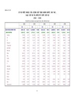
Learning AutoCAD 2010, Volume 1 phần 4 docx
Bạn đang xem bản rút gọn của tài liệu. Xem và tải ngay bản đầy đủ của tài liệu tại đây (7.5 MB, 46 trang )
Lesson: Using Polar Tracking and PolarSnap ■ 125
Exercise: Use Polar Tracking and PolarSnap
In this exercise, you create lines at precise distances and angles using polar tracking and PolarSnap. When
you have completed the exercise, you will be able to use the polar tracking and PolarSnap features to create
precise geometry.
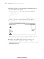
The completed exercise
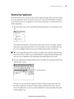
Completing the Exercise
To complete the exercise, follow the
steps in this book or in the onscreen
exercise. In the onscreen list of
chapters and exercises, click Chapter 2:
Creating Basic Drawings. Click Exercise:
Use Polar Tracking and PolarSnap.
1.
Open M_Roller.dwg.
2.
On the status bar, make sure the following
settings are on:
■ Snap
■ Polar tracking
■ Object snap
■ Model
Right-click Polar Tracking and select Settings.
3.
In the Drafting Settings dialog box, Polar
Tracking tab:
■ Select 15 from the Increment Angle list.
■ Under Polar Angle Measurement, click
Absolute.
126 ■ Chapter 2: Creating Basic Drawings
4.
On the Snap and Grid tab:
■ Click PolarSnap.
■ Enter 1 in the Polar Distance field.
5.
On the Object Snap tab:
■ Make sure Endpoint and Node are
selected.
■ Click OK.
6.
To draw the line using polar tracking:
■ Activate the Line tool.
■ Specify the line's start point from the
point object, using the Node object snap
override.
■ Drag the cursor to the right until the polar
tracking tooltip reads 25.00 < 0 degrees.
Click the point.
7.
Position the cursor so that the polar angle
tooltip reads 15.00 < 45. Click the point.
8.
Position the cursor so that the polar angle
tooltip reads 25.00 < 0. Click the point.
9.
Position the cursor so that the polar angle
tooltip reads 15.00 < 315. Click the point.
Lesson: Using Polar Tracking and PolarSnap ■ 127
10.
Position the cursor so that the polar angle
tooltip reads 25.00 < 0. Click the point.
11.
Move the cursor upwards until the polar
tracking cursor reads 70.00 < 90. Click the
point.
12.
Repeat these steps to draw the top half of the
object which mirrors the bottom half, changing
the Polar angle accordingly. Your final endpoint
should be at the original start point.
13.
Press ENTER to repeat the Line command.
Select the endpoints indicated in the following
image to draw the inner vertical lines. Press
ENTER to end the Line command.
14.
Close all files. Do not save.
128 ■ Chapter 2: Creating Basic Drawings
Lesson: Using Object Snap Tracking
In this lesson, you learn what object snap tracking is and how it can assist you in creating geometry.
When you have completed the lesson, you will be able to describe and use object snap tracking to
position geometry.
Object snap tracking is the most efficient way to locate a point using your existing objects as
reference.
In the following image, object snap tracking is used to quickly locate the center of the rectangle.
Objectives
After completing this lesson, you will be able to:
■ Describe object snap tracking.
■ Use object snap tracking to position geometry.
Lesson: Using Object Snap Tracking ■ 129
About Object Snap Tracking
You often need to place or create geometry at a location relative to other objects in the drawing. While
you could create construction geometry for the purpose of aligning the new geometry, with object
snap tracking you can accomplish the same result much faster.
Object Snap Tracking Defined
Object snap tracking works in combination with object snaps to enable you to temporarily acquire and
track up to seven points. Once you acquire points, object snap tracking provides horizontal, vertical, or
polar alignment paths relative to the points that you have acquired.
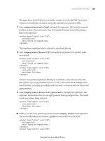
In the following image, the table is being moved to the room center using object snap tracking. To
center the table in the room, the midpoint of the wall on the left (1) and the midpoint of the wall
below (2) have been acquired. Triangular glyphs at the midpoints indicate that the points have been
acquired. As the table is positioned near the imaginary intersection, the alignment paths (3) appear
indicating the intersection. The Dynamic Input interface displays the current position as 0 degrees from
the left midpoint and 90 degrees from the lower midpoint.
130 ■ Chapter 2: Creating Basic Drawings
When you need to know the center of a noncircular object such as a rectangle or polygon, use object
snap tracking to locate the center point.
Object Snap Tracking Guidelines
■ Use object snap tracking to reduce the need to create construction geometry.
■ You can use object snap tracking to calculate the center point of noncircular objects.
■ When you use object snap tracking in conjunction with dynamic input, the Dynamic Input
interface displays position information related to the acquired points.
Using Object Snap Tracking
To use object snap tracking, you acquire points from geometry in the drawing using running object
snaps. As you acquire points on the geometry, a small plus (+) sign appears on the point. This indicates
that the point is being used for object snap tracking.
In the following image, the midpoint of the left side of the rectangle has been acquired. Notice the
plus (+) symbol indicating the acquired point. The midpoint of the bottom of the rectangle is being
touched to acquire the point.
Lesson: Using Object Snap Tracking ■ 131
Touching to Acquire a Point
To touch a point, hover over the point with your cursor but DO NOT CLICK to select
the point. The acquired indicator appears inside the object snap marker when the
point has been acquired.
Command Access
Object Snap Tracking
Menu Bar: Tools > Drafting Settings > Object Snap / Object Snap Tab
Keyboard Shortcut: F11
Status Bar: Object Snap Tracking > Right-click > Settings
Drafting Settings Dialog Box
Turn Object Snap Tracking on from the Status Bar, from the Object Snap tab in the Drafting Settings
dialog box, or by pressing F11. Object Snap must be on and modes must be selected for Object Snap
Tracking to work.
132 ■ Chapter 2: Creating Basic Drawings
In the Polar Tracking tab, you can choose whether to track Orthogonally Only (simplest method) or to
Track using all polar angle settings.
Alignment paths only appear for horizontal and vertical alignments.
Alignment paths appear for all polar angles defined.
Press and hold SHIFT+Q to temporarily turn object snap tracking on or off.
Procedure: Using Object Snap Tracking
The following steps outline how to use object snap tracking to acquire points.
1.
On the status bar, make sure the Osnap and Otrack settings are on.
2.
Start any command that prompts you to select a point.
Lesson: Using Object Snap Tracking ■ 133
3.
To specify a point using object snap tracking, touch the point with the cursor. A small plus (+) appears,
indicating that the point has been acquired.
4.
Touch another point to acquire its location.
5.
If more than two points are required, continue to touch points.
6.
Move your cursor to a location that would be considered an intersection of the acquired points, based
on orthogonal or polar angle settings. The alignment paths appear as your cursor approaches the
calculated intersection.
7.
Click to select the calculated point.
134 ■ Chapter 2: Creating Basic Drawings
Guidelines for Acquiring Points with Object Snap Tracking
■ To acquire a point, touch it with the cursor.
■ To release a point, touch an acquired point with the cursor.
■ You can acquire up to seven points for object snap tracking.
■ If you attempt to acquire more than seven points, previous points are automatically released on a
first-acquired, first-released basis.
Object Snap Tracking Settings Key Points
■ Object snap tracking uses running object snaps to acquire points.
■ To use object snap tracking, object snaps must be turned on with at least one object snap
selected.
■ Hover over the object snap points but do not select them.
Lesson: Using Object Snap Tracking ■ 135
Practice Exercise: Object Snap Tracking
Practice using object snap tracking orthogonally.
1.
Begin a new drawing.
2.
Be sure that Object Snap and Object Snap
Tracking are both selected in the status bar.
Right-click Object Snap and be sure that the
Midpoint selection mode is selected.
3.
Draw a rectangle any size:
■ On the Home tab, click Draw panel >
Rectangle.
■ Click the first corner; click the opposite
corner.
4.
Draw a circle (any size) in the center of the
rectangle:
■ On the Home tab, click Draw panel > Circle.
■ Hold the mouse over the midpoint of one
of the lines in the rectangle until you see a
small cross.
■ Then hold the mouse over the midpoint of
one of the adjacent lines.
■ Then bring your curser to the middle of the
rectangle.
■ Click at the intersection of the two dotted
lines of the horizontal and polar angles.
■ Specify the circle size by clicking a point in
the graphics window, or entering a value on
the command line.
5.
Close all files. Do not save.
136 ■ Chapter 2: Creating Basic Drawings
Exercise: Use Object Snap Tracking
In this exercise, you use object snap tracking to create a side view of the part. After completing this lesson,
you will be able to use object snap tracking in other drawings.
The completed exercise
Completing the Exercise
To complete the exercise, follow the
steps in this book or in the onscreen
exercise. In the onscreen list of
chapters and exercises, click Chapter 2:
Creating Basic Drawings. Click Exercise:
Use Object Snap Tracking.
1.
Open M_Object-Tracking.dwg.
2.
On the status bar, make sure the following
settings are turned on:
■ Polar tracking
■ Object snap
■ Object snap tracking
■ Dynamic input
3.
Right-click Object Snap Tracking. Click Settings.
4.
In the Drafting Settings dialog box, select the
running object snaps as shown in the following
image. Click OK.
5.
To draw a rectangle:
■ On the Home tab, click Draw panel >
Rectangle.
■ Acquire the lower right corner of the
existing shape and move the mouse to the
right along the extension path.
■ Enter 40 in the Dynamic Input field. Press
ENTER.
Lesson: Using Object Snap Tracking ■ 137
■ Move the cursor up and to the right.
■ Enter 31.75, 69.85. Press ENTER.
6.
To repeat the rectangle command:
■ Right-click in the graphics window. Click
Repeat RECTANG.
■ Select the lower right corner of the
previous rectangle as the start point.
■ Enter 17.53, 25.4. Press ENTER.
7.
To draw a line:
■ On the Home tab, click Draw panel > Line.
■ Select the top right corner of the first
rectangle.
■ Move the cursor to the right at 0 degrees.
Enter 90.55. Press ENTER.
8.
Move the cursor to acquire a tracking point
from the lower right corner of the second
rectangle. Track back to the line until the angle
shows 90 degrees. Click to select the point.
138 ■ Chapter 2: Creating Basic Drawings
9.
Move the cursor to the left. Enter 46.1. Press
ENTER.
10.
Acquire the point where the arc and angled
line meet (1). Track back to the point where
the current line meets the tracking line (2).
Click the intersection of the alignment paths.
11.
Acquire the midpoint of the top line of the
second rectangle. Track upwards until you get
to the intersection of the two tracking lines.
Click that point.
12.
Select the midpoint of the top line of the
second rectangle. Press ENTER to complete the
line command.
13.
Close all files. Do not save.
Lesson: Working with Units ■ 139
Lesson: Working with Units
This lesson describes how to set up units in a drawing.
When you create drawings, one of the first things you must do is define the current working units. The
units settings determine how you enter distances as well as how the values are returned to you.
The following illustration shows how the software presents the current units through the dynamic
input interface.
Objectives
After completing this lesson, you will be able to:
■ Describe units and how they affect your drawing.
■ Use the Units command to set drawing units.
140 ■ Chapter 2: Creating Basic Drawings
About Units
Units represent the baseline of all the geometry that you create in your drawing. It is up to you to
determine what unit of measurement will be used in your drawing.
When you begin a blank drawing, the default units are based in the decimal system. Because the
software is not capable of distinguishing inches from millimeters, it assumes that a value of 1 is equal
to either 1 inch or 1 mm. Setting the appropriate units determines the format in which the software
presents values to you via the command line, status bar, polar tracking, and dynamic input interface.
While the software is not a true units-based system, meaning it doesn't understand the difference
between 1 inch and 1 millimeter, there are some assumptions that can affect other settings such as
Imperial Architectural units (for example1'-6"), and alternate dimension display.
Unit Guidelines
The following are some guidelines you should refer to regarding units:
■ The software is set by default to decimal units.
■ A unit of 1 can be equal to 1 inch or 1 millimeter.
■ If you need to input imperial architectural units for distances, you must select the Architectural
type drawing units. The software will not understand the architectural units format 1'-6" if the
Units are set to Decimal.
■ When you are using Architectural Units, type the 'foot' mark, but it is not necessary to type
"inches" as the software will assume inches if no symbol is typed. Example 16' -2" can be simply
typed: 16'2
■ When using Architectural units, you may type 16' -2" or the equivalent in inches: 194
■ If you work primarily with metric units, then you should use the default decimal unit setting.
■ AutoCAD is accurate 14 decimal places (1.00000000000000). What you see for units precision will
be rounded up to the nearest decimal place that you have determined in the Units dialog box.
■ Simply picking points in the drawing window will not guarantee that you have specified the
precise length or angle unless you use the drawing aids determined in the drafting settings.
Lesson: Working with Units ■ 141
Units Example
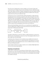
The following image illustrates the assumptions made regarding units. In this image, a single line was
drawn at a length of 18 units. When dimensioned with both a metric and imperial dimension style, the
dimensions report different lengths.
This occurs because the default dimension styles have preset conversion factors when you display
alternate units. While you could change these conversion factors to represent any conversion
imaginable, by default the software assumes a conversion using inches or millimeters as the base unit.
Setting Units
You use the Units command to set up the units for the drawing. You can change the drawing units at
any time, but it is recommended that you do so at the beginning of each drawing you create.When you
use drawing templates or the New Drawing wizard, the units for the drawing are set accordingly.
In the following image, the drawing units have been set to accept surveyor units for angle input.
Command Access
Units
Command Line: UNITS
Application menu: Drawing Utilities > Units
142 ■ Chapter 2: Creating Basic Drawings
Drawing Units Dialog Box
When you start the Units command, the Drawing Units dialog box is displayed. You set the unit types
for length, angle, and insertion scale. You can set the precision for both length and angle units and you
can also set the angle direction. The precision options are displayed in the selected unit format.
To set your drawing units, select the appropriate unit in the Length and Angle lists and then set the
unit's precision with the Precision lists for length and angle.
Current Unit Setting
The current unit setting affects the manner in which values are presented to you as
well as the format in which you can enter distances and angles. Regardless of the
unit setting you choose, you can always enter values in decimal format.
Warning!
The Lighting area shown in the Units dialog box is not available in AutoCAD LT.
Lesson: Working with Units ■ 143
Procedure: Setting Drawing Units
The following steps give an overview of setting drawing units.
1.
On the command line, enter units and press ENTER.
2.
In the Drawing Units dialog box, select the appropriate length and angle unit types. If necessary, you
can also adjust the precision options for both length and angle.
3.
Click OK.
4.
You can now enter values using the format of the selected unit for length and angle. When the software
presents values to you via the interface, they are in the selected unit format.
Guidelines for Setting Units
■ While it is possible to set the drawing units at any time, it is recommended that you do this when
you start a new drawing.
■ Regardless of the current unit setting, you can always enter units in decimal format.
■ To input values in a format other than decimal, you must set the appropriate unit type.
144 ■ Chapter 2: Creating Basic Drawings
Practice Exercise: Setting Units
In this practice exercise, you create a new blank
drawing, set the drawing units to Architectural, and
draw a rectangle 54' 6" x 34'2". Then you zoom all to
see your work.
1.
Begin a new drawing. In the Select template
dialog box, select the acad drawing template.
2.
To set the architectural drawing units:
■ On the command line, enter units and
press ENTER.
■ In the Drawing Units dialog box, under
Length, select Architectural in the Type list.
■ Click OK to exit.
3.
To draw the 54'6" x 34'2" rectangle:
■ On the Home tab, click Draw panel >
Rectangle.
■ Specify the first corner point.
■ To specify the opposite corner, enter:
@54'6,34'2
Note: You do not have to enter inches.
4.
To zoom your drawing:
■ Enter Z and press ENTER.
■ Enter A and press ENTER.
Lesson: Working with Units ■ 145
Exercise: Use Architectural Units
In this exercise, you set the drawing to use architectural units. Then, using the dynamic input interface, you
sketch the outline of a simple floor plan.
The completed exercise
Completing the Exercise
To complete the exercise, follow the
steps in this book or in the onscreen
exercise. In the onscreen list of
chapters and exercises, click Chapter 2:
Creating Basic Drawings. Click Exercise:
Use Architectural Units.
1.
Open I_Architectural-Units.dwg.
2.
To set the unit type:
■ Click the Application button > Drawing
Utilities > Units.
■ In the Type list under Length, select
Architectural.
■ In the Precision list, select 0'-0 1/8".
■ In the Precision list under Angle, select 0.0.
■ Click OK.
3.
To draw a line:
■ On the Home tab, click Draw panel > Line.
■ Enter 10',10'. Press ENTER.
■ Move the cursor to the right.
■ Enter 6'-8. Press TAB.
■ Enter 0. Press TAB.
■ Click anywhere in the drawing.
146 ■ Chapter 2: Creating Basic Drawings
4.
For the next point:
■ Move the cursor down and to the right.
■ Enter 2'4.25. Press TAB. Enter 45. Press TAB
again.
■ Click anywhere in the drawing to accept
the point.
5.
For the next point:
■ Enter 4'. Press TAB.
■ Enter 0. Press TAB.
■ Move the cursor to the right.
■ Click anywhere in the drawing to accept
the point.
6.
For the next point:
■ Move the cursor up and to the right.
■ Enter 2'4-1/4. Press TAB.
■ Enter 45. Press TAB.
■ Click anywhere in the drawing to accept
the point.
7.
For the next point:
■ Move the cursor to the right.
■ Enter 45'-8". Press TAB.
■ Enter 0. Press TAB.
■ Click anywhere in the drawing.
8.
For the next point:
■ Move the cursor up.
■ Enter 42'-8". Press TAB.
■ Enter 90. Press TAB.
■ Click anywhere in the drawing.
9.
For the next point:
■ Move the cursor to the left.
■ Enter 15'-3". Press TAB.
■ Enter 180. Press TAB.
■ Click anywhere in the drawing.
10.
For the next point:
■ Move the cursor down.
■ Enter 6'-2". Press TAB.
■ Enter 90. Press TAB.
■ Click anywhere in the drawing.
Lesson: Working with Units ■ 147
11.
For the next point:
■ Move the cursor to the left.
■ Enter 44'-5". Press TAB.
■ Enter 180. Press TAB.
■ Click anywhere in the drawing.
12.
Right-click and click Close, or select the
endpoint of the line where you started.
13.
Close all files. Do not save.
148 ■ Chapter 2: Creating Basic Drawings
Exercise: Use Surveyor's Units
In this exercise, you set the drawing units to accept
Surveyor's Units for angle input, and use the Dynamic
Input interface to draw a site boundary.
The completed exercise
Completing the Exercise
To complete the exercise, follow the
steps in this book or in the onscreen
exercise. In the onscreen list of
chapters and exercises, click Chapter 2:
Creating Basic Drawings. Click Exercise:
Use Surveyor's Units.
1.
Open M_Survey-Units.dwg.
2.
To set the unit type:
■ Click Application Button > Drawing Utilities
> Units.
■ In the Angle type list, select Surveyor's
Units.
■ In the Angle Precision list, select N
0d00'00" E.
■ Click OK.
3.
To draw a line:
■ On the Home tab, click Draw panel > Line.
■ Enter 4000,4000. Press ENTER.
■ Enter 17497. Press TAB.
■ Enter N85d14' E. Press TAB.
■ Click anywhere in the drawing.
4.
For the next point:
■ Move the cursor up and to the right from
the previous point.
■ Enter 25498. Press TAB.
■ Enter N2d57' E. Press TAB.
■ Click anywhere in the drawing.
Lesson: Working with Units ■ 149
5.
For the next point:
■ Move the cursor up and to the left from
the previous point.
■ Enter 19000. Press TAB.
■ Enter N80d40' W. Press TAB.
■ Click anywhere in the drawing.
■ Right-click and click Close.
The site boundary appears as shown.
6.
Close all files. Do not save.