Learning AutoCAD 2010, Volume 1 phần 9 pot
Bạn đang xem bản rút gọn của tài liệu. Xem và tải ngay bản đầy đủ của tài liệu tại đây (7.49 MB, 46 trang )
Challenge Exercise: Architectural ■ 355
2.
Create nine layers with the following names and color properties:
■ Annotation = white
■ Dimension = red
■ Doors = 30
■ Plumbing Fixtures = magenta
■ Stairs = white
■ Titleblock = red
■ Wall-Interior = cyan
■ Windows = blue
■ Viewports = 9
3.
Put the stair geometry on the Stairs layer and the door geometry on the Doors layer.
4.
Thaw the Existing Building - Apparatus Bay layer.
5.
Save and close the drawing.
Completing the Exercise
To complete the exercise, follow the steps in this book or in the onscreen exercise. In
the onscreen list of chapters and exercises, click Chapter 4: Drawing Organization and
Inquiry Commands. Click Challenge Exercise: Architectural Imperial.
Imperial Units
1.
Open the drawing you saved from the previous challenge exercise, or open I_ARCH-Challenge-
CHP04.dwg.
2.
Create nine layers with the following names and color properties:
■ Annotation = white
■ Dimension = red
■ Doors = 30
■ Plumbing Fixtures = magenta
■ Stairs = white
■ Titleblock = red
■ Wall-Interior = cyan
■ Windows = blue
■ Viewports = 9
3.
Put the stair geometry on the Stairs layer and the door geometry on the Doors layer.
4.
Thaw the Existing Building - Apparatus Bay layer.
5.
Save and close the drawing.
356 ■ Chapter 4: Drawing Organization and Inquiry Commands
Challenge Exercise: Mechanical
In this exercise, you use what you learned about drawing organization and inquiry commands to add
layers and hidden geometry to the drawing views.
Note: The following image depicts only some of the views requiring hidden line geometry.
The completed exercise
Completing the Exercise
To complete the exercise, follow the steps in this book or in the onscreen exercise. In
the onscreen list of chapters and exercises, click Chapter 4: Drawing Organization and
Inquiry Commands. Click Challenge Exercise: Mechanical.
1.
Open the drawing you saved from the previous challenge exercise, or open M_MECH-Challenge-
CHP04.dwg.
2.
Open the Layer Properties Manager:
■ Create a new layer named Hidden and make it the current layer.
❏ Color = 151
❏ Linetype = Hidden
■ Create a new layer named Centerline.
❏ Color = Magenta
❏ Linetype = Center
■ Create a new layer named Annotation.
❏ Color = Magenta
❏ Linetype = Continuous
■ Freeze and lock the Start Points layer.
3.
Set the LTSCALE system variable to 0.75.
Challenge Exercise: Mechanical ■ 357
4.
With the Hidden layer current, create the hidden geometry in these views using points in each view as
references. Then create the centerline objects and place them on the Centerline layer.
Note: In the following image, the views are closer together than they are in the drawing.
5.
Save and close all files.
358 ■ Chapter 4: Drawing Organization and Inquiry Commands
Chapter Summary
There is more to creating drawings than drawing lines, circle, and arcs. Part of the drawing process
involves the use of layer and linetype standards as well as retrieving geometric information from
objects in the drawing.
Having completed this chapter, you can:
■ Use layers to organize objects in your drawing.
■ Identify and change the properties of objects.
■ Use the Quick Properties palette to quickly change object properties.
■ Use the Match Properties command to apply the properties from a source object to destination
objects.
■ Use the Properties palette to change object properties.
■ Use linetypes to distinguish objects in the drawing.
■ Use the Inquiry commands (Distance, Radius, Angle, Area, List, and ID) to obtain geometric
information from the drawing.
■ In this exercise, you use what you learned about drawing organization and inquiry commands to
create layers, manipulate objects and their layers, and create additional geometry on its correct
layer.
■ In this exercise, you use what you learned about drawing organization and inquiry commands to
add layers and hidden geometry to the drawing views.
Chapter Overview ■ 359
Chapter
5
Altering Objects
Of all CAD design tasks, editing objects is most common. Editing is something you will be required to
do nearly every time you draw whether as the result of design changes or just the standard practice of
creating more complex objects from simple ones.
Objectives
After completing this chapter, you will be able to:
■ Change the length of objects using the Trim and Extend commands.
■ Create parallel and offset geometry in your drawing by using the Offset command.
■ Use the Join command to combine multiple objects into a single object.
■ Break objects into two or more independent objects.
■ Apply a radius corner to two objects in the drawing.
■ Apply an angled corner to two objects in the drawing.
■ Use the Stretch command to alter the shape of objects in the drawing.
Standard Object Snap and Status Bar Settings
Before completing the exercises in this chapter, refer to the "Settings for the
Exercises" section in the Introduction in Volume 1.
360 ■ Chapter 5: Altering Objects
Lesson: Trimming and Extending Objects to
Lesson: Defined Boundaries
This lesson describes how to trim and extend objects in the drawing.
A typical design process involves shortening or lengthening the construction lines or other geometry
at various times to represent the design's features.
After completing this lesson, you will be able to describe the uses of the Trim and Extend commands
to modify objects, cut edges, and extend boundaries in your drawing.
The following image illustrates lines that need to be trimmed.
Objectives
After completing this lesson, you will be able to:
■ Use the Trim and Extend commands to modify geometry in your drawing.
Lesson: Trimming and Extending Objects to Defined Boundaries ■ 361
Using the Trim and Extend Commands
You can use the Trim command to shorten and the Extend command to lengthen existing geometry
to meet the edges of other objects. This means that you can create an object such as a line and later
adjust it to fit precisely between other objects.
When you use the Trim command, you select objects to use as cutting edges and trim geometry back
to those objects. You select the portion of the object to trim, not the portion to keep.
In the following image, the arrows indicate where you would click to trim the lines.
When you use the Extend command, you select objects to use as boundary edges and extend
geometry to those objects.
In the following illustration, the boundary edge (2) is indicated with an arrow. Selecting the lines (1) at
the location of the arrows extends each line to the first boundary edge it encounters. The completed
command is illustrated in the image on the right.
Before extend and after extend
362 ■ Chapter 5: Altering Objects
Command Access
Trim
Command Line: TRIM, TR
Ribbon:
Home tab > Modify panel > Trim
Menu Bar: Modify > Trim
Command Access
Extend
Command Line: EXTEND, EX
Ribbon: Home tab > Modify panel > Extend
Menu Bar: Modify > Extend
Lesson: Trimming and Extending Objects to Defined Boundaries ■ 363
Procedure: Trimming Objects
The following steps give an overview of using the Trim command to shorten objects to cutting edges.
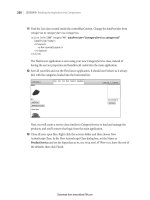
1.
On the ribbon, click Home tab > Modify panel > Trim.
2.
Either select the objects to serve as cutting edges (1) and then press ENTER, or press ENTER without
selecting any objects. Pressing ENTER without selecting activates implied selection, where all suitable
objects in the drawing are treated as potential cutting edges.
3.
Select the objects to trim (2).
364 ■ Chapter 5: Altering Objects
4.
Press ENTER to end the command and view your completed operation.
Procedure: Extending Objects
The following steps give an overview of using the Extend command to lengthen objects to boundary
edges.
1.
On the ribbon, click Home tab > Modify panel > Extend.
2.
Either select the objects to serve as boundary edges (1) and then press ENTER, or press ENTER without
selecting any objects. Pressing ENTER without selecting, activates implied selection, where all suitable
objects in the drawing are treated as potential boundary edges.
Lesson: Trimming and Extending Objects to Defined Boundaries ■ 365
3.
Select the objects to extend (2).
4.
Press ENTER to end the command and view your completed operation.
366 ■ Chapter 5: Altering Objects
Guidelines for Trim and Extend
Consider the following guidelines when using the Trim and Extend commands:
■ Cutting or boundary edges may be lines, arcs, circles, polylines, ellipses, splines, xlines, regions,
blocks, text, and rays.
■ If you do not specify a cutting or boundary edge and press ENTER instead at the Select Objects
prompt, all objects become potential cutting edges or boundaries. This is called implied selection.
■ If you hold down the SHIFT key, you can SHIFT + select to switch between Trim and Extend. For
example, if you are in the Trim command, you can hold down SHIFT and select objects to be
extended to the boundary edge. Similarly, you can be in the Extend command and use SHIFT +
select to trim objects to a cutting edge.
■ Cutting and boundary edges do not have to intersect the object being trimmed or extended if you
use the Edge option set in the Extend mode. With this setting, you can trim or extend an object
to where it would intersect if the cutting or boundary edges were extended. For example, in the
following illustration, the lower line (2) in the left illustration can be extended as if line (1) really
was extended to point (3) as shown in the illustration on the right.
Extended Edge Mode
Guidelines for Trim and Extend Options
■ The default edge mode for Trim and Extend is No Extend. Most of the time, you will want to use
these commands with this default setting.
■ The Trim or Extend Project option is for 3D.
■ The Trim or Extend eRase option enables you to erase line segments within either of these
commands.
■ The Trim or Extend Undo option enables you to reverse an action you have made to trim or extend
without exiting either of these commands.
Note: You can right-click to select these options from the shortcut menu or you can type the
capitalized letter of the option at the Command line and press Enter.
Lesson: Trimming and Extending Objects to Defined Boundaries ■ 367
Practice Exercise: Trim and Extend
In this practice exercise, you use the Trim and Extend
commands. First, draw two rectangles. Across one
rectangle, draw a series of lines that intersect the
rectangle. Inside the other rectangle, create lines
that do not touch the sides of the rectangle as
shown below. You also practice the Trim and Extend
commands using the Fence selection option.
1.
To set up this practice exercise:
■ Draw two rectangles of any size.
■ Across one rectangle, draw a series of lines
that intersect the rectangle.
■ Inside the other rectangle draw a line that
is completely inside and copy it several
times.
2.
To use the Trim command, select the cutting
edges first:
■ On the Home tab, click Modify panel >
Trim.
■ Select the rectangle for the cutting edge.
■ Press ENTER.
3.
To trim the lines:
■ Click the portion of the line segment that
you want to remove.
■ Trim all of the line segments to the left of
the rectangle as indicated below.
4.
Continue to trim, this time using the Fence
option:
■ Right-click in the graphics window. Click
Fence.
■ Click the first fence point just above the
series of line segments to the right of the
rectangle (1).
■ Click the next fence point just below the
bottom line segment to the right of the
rectangle (2).
368 ■ Chapter 5: Altering Objects
5.
To complete the Trim command:
■ Press ENTER to complete the Fence
selection option.
■ Press ENTER to exit the Trim command.
6.
To use the Extend command, select the
boundary edges first:
■ On the Home tab, click Modify panel >
Extend.
■ Select the rectangle for the boundary edge.
■ Press ENTER.
7.
To extend the lines, select the line near the end
that you want to extend:
■ Click each line towards the left of the
rectangle (1).
■ Right-click. Click Fence.
Lesson: Trimming and Extending Objects to Defined Boundaries ■ 369
■ Click just above the line towards the right
side of the rectangle (1).
■ Click just below the bottom line (2) as
indicated below.
8.
To complete the Extend command:
■ Press ENTER to complete the Fence
selection line option.
■ Press ENTER to exit the Extend command.
■ View your results.
370 ■ Chapter 5: Altering Objects
Exercise: Trim and Extend Objects
In this exercise, you use the Trim and Extend
commands to trim and extend edges on the drawing.
When you have completed the exercise, you will be
able to trim and extend geometry using standard trim
and extend methods. You will also be able to use the
Edge option to extend or trim geometry to implied
intersections and the SHIFT+select feature to switch
between trimming and extending.
The completed exercise
Completing the Exercise
To complete the exercise, follow the
steps in this book or in the onscreen
exercise. In the onscreen list of
chapters and exercises, click Chapter
5: Altering Objects. Click Exercise: Trim
and Extend Objects.
1.
Open M_Trim-Extend.dwg.
2.
Zoom to display the view as shown in the
following image.
3.
Use the Trim command to complete the slot
geometry:
■ On the Home tab, click Modify panel >
Trim.
■ Select the lines highlighted in the following
image as the cutting edges.
■ Press ENTER.
4.
Select the lines to trim at the points indicated
in the following image. Press ENTER.
Lesson: Trimming and Extending Objects to Defined Boundaries ■ 371
Your drawing should appear as shown in the
following image.
5.
Zoom out to display the entire drawing.
6.
To use the Extend command:
■ On the Home tab, click Modify panel >
Trim drop-down > Extend.
■ Select the geometry highlighted in the
following image as your boundary edges.
■ Press ENTER.
7.
To complete the view on the left:
■ Right-click anywhere in the drawing
window. Click Edge.
■ Right-click anywhere in the drawing
window. Click Extend.
■ Select the geometry indicated in the
following image as the objects to extend.
Note: You need to select the two horizontal
lines twice because they are initially extended
to the first boundary. The second selection
extends them to the next boundary that the
edge intersects.
Your drawing should appear as shown in the
following image.
8.
SHIFT+select the lines indicated in the previous
image to trim them.
9.
Press ENTER to end the Extend command.
372 ■ Chapter 5: Altering Objects
10.
To remove the construction lines:
■ Start the Erase command.
■ Select the lines indicated in the following
image. Press ENTER.
11.
Your completed drawing.
12.
Close all files. Do not save.
Lesson: Creating Parallel and Offset Geometry ■ 373
Lesson: Creating Parallel and Offset Geometry
This lesson describes how to use the Offset command to create geometry that is offset from or parallel
to other geometry in the drawing.
In a typical drawing, you are likely to find several objects that are parallel to or offset from each
other. You can use the Offset command to create this effect on geometry in the drawing and increase
efficiency by reusing existing geometry.
The following illustration shows several parallel lines and concentric circles. The Offset command can
be used to create these types of objects.
Objectives
After completing this lesson, you will be able to:
■ Use the Offset command to create parallel and offset geometry.
374 ■ Chapter 5: Altering Objects
Offsetting Objects
The Offset command creates a new object whose shape parallels the shape of a selected object.
For example, in the following image, the inside shape has been offset twice using the Offset command
with the Multiple option.
Command Access
Offset
Command Line: OFFSET, O
Ribbon: Home tab > Modify panel > Offset
Application Menu: Modify > Offset
Lesson: Creating Parallel and Offset Geometry ■ 375
Command Options
The Offset command has the following options. From the shortcut menu, either right-click to select the
option or enter the capitalized letter and press ENTER.
Option
Description
Through
Offsets a selected object the distance of a point picked in the drawing window.
Erase
Erases the source object after it has been offset.
Layer
Offsets the object to the original source layer or the current layer.
Multiple
Makes multiple offsets of the object in increments specified by the offset distance.
Procedure: Offsetting Geometry a Specific Distance
The following steps give an overview of offsetting geometry a specified distance.
1.
On the ribbon, click Home tab > Modify panel > Offset.
2.
Specify the offset distance by selecting two points.
Note: You can enter a value instead of selecting points.
3.
Select the object to offset.
376 ■ Chapter 5: Altering Objects
4.
Select a point on the side where you want to place the new objects.
5.
Select another object to offset or exit the command.
Procedure: Offsetting Geometry Through a Point
The following steps give an overview of using the Offset command with the Through option to offset a
line through a point on a circle.
1.
On the Home tab, click Modify panel > Offset.
2.
Right-click anywhere in the drawing. Click Through. You can also enter t on the command line.
3.
Select the object to offset.
4.
Specify the point through which to offset the object. Note: The top horizontal line represents the
position of the object after the offset. If it were extended, it would pass through the point indicated by
the cursor.
5.
Select another object to offset or exit the command.
Lesson: Creating Parallel and Offset Geometry ■ 377
Procedure: Offsetting Multiple Objects
The following steps give an overview of serially offsetting geometry a specified distance using the
Multiple option.
1.
On the Home tab, click Modify panel > Offset.
2.
Specify the offset distance by entering a value or selecting two points.
3.
Select the object to offset.
4.
Right-click anywhere in the drawing. Click Multiple.
5.
Select a point on the side where you want to place the new objects.
378 ■ Chapter 5: Altering Objects
6.
Select another point to offset the last object by the same amount.
7.
Continue selecting points to repeat the offset on the last object created.
Guidelines for Using the Offset Command
■ Setting the offset distance is the default and most common method for using offset. Enter the
distance and press ENTER.
■ The offset distance may also be set by picking two points in the drawing window. When using
this method, it is best to use object snap and reference objects in the drawing to accurately set a
distance.
■ When you begin the Offset command, the last offset distance used is displayed in the Command
line. Press Enter to accept this distance, or enter a new offset distance then press ENTER.
■ Use the Multiple option to create a series of offsets once you have selected the original object to
offset. Then simply click the side to offset as many times as needed.
■ An offset object will automatically retain the color, layer, and linetype of the source object unless
you change the offset Layer option to Current. The most common method is to keep the offset
objects on the source layer.
■ When you offset a circle, arc or polyline, at some point it may not be possible to create the offset
to the inside or outside of the object because of geometry restrictions. For example, if the offset
distance is greater than the radius of a circle, it would be impossible to offset to the inside of that
circle.
■ You remain in the Offset command until you press ENTER, unless you have initiated the Through
option. Then only one offset is created through the object selected.
Lesson: Creating Parallel and Offset Geometry ■ 379
Practice Exercise: Offsetting Objects
In this practice exercise, you practice using the Offset
command with three different methods. First, draw
a circle, a line, and a rectangle, and then offset the
rectangle a specific distance. Offset the circle through
a selected point. Make multiple offsets of the line.
1.
To offset a distance:
■ On the Home tab, click Modify panel >
Offset.
■ Enter an offset distance of .05. Press
ENTER.
■ Select the rectangle (1).
■ Click inside the rectangle.
■ Select the new rectangle (2).
■ Click inside the rectangles.
■ Select the next rectangle (3) and click
inside the rectangles.
■ Press ENTER to complete the Offset
command.
2.
To offset through a point:
■ On the Home tab, click Modify panel >
Offset.
■ Right-click in the drawing window. Click
Through.
■ Select the object to offset. Select the Circle.
■ Specify a point through another object.
Select anywhere on the adjacent rectangle.
■ Press ENTER to exit the Offset command.