Mastering Autodesk Maya 2011 phần 4 potx
Bạn đang xem bản rút gọn của tài liệu. Xem và tải ngay bản đầy đủ của tài liệu tại đây (2.64 MB, 105 trang )
286
|
CHAPTER 5 anIMatIon teChnIques
7. Move the bodyCtrl curve back and forth on the z-axis, and you’ll see that the front left leg
now walks with the bug.
8. Save the scene as mechBugWalk_v03.ma.
To see a version of the scene to this point, open the mechBugWalk_v03.ma scene from the
chapter5\scenes directory on the DVD.
Copying and Pasting Driven Keys
The trick at this point is to create the same driven key arrangement for the other five legs in the
easiest way possible. You can achieve this using Copy and Paste. The important thing to remem-
ber is that to paste driven keys from a channel on one object to another, you should have one
driven key already created for the target objects.
1. Continue with the scene from the previous section, or open the mechBug_v03.ma scene
from the chapter5\scenes directory on the DVD.
2. From the Animation menu set, choose Animate Set Driven Key Set to open the Set
Driven Key window.
3. Select the bodyCtrl curve, and load it as the driver.
4. Select all the leg control curves except the frontLeftLegCtrl.
5. Click the Load Driven button.
6. Make sure the Translate Z channel of the bodyCtrl curve is at 0. Set the Translate Z of the
five leg control curves to -1.
7. Select the Translate Z channel in the upper right of the Set Driven Key window. In the
lower left, make sure all the leg control curves are selected.
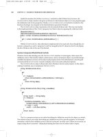
8. Select the Translate Y and Translate Z channels in the lower right (see Figure 5.49).
Figure 5.48
The Pre- and Post-
Infinity values of
the Translate Z
channel are set to
Cycle With Offset
so it continually
steps as the bug is
moved back and
forth.
drIVen keys
|
287
9. Click the Key button to create an initial key for the five legs. You can close the Set Driven
Key window.
10. Make sure the bodyCtrl curve’s Translate Z channel is at 0. Select the frontLeftFootCtrl
curve. In the Channel Box, highlight the Translate Y and Translate Z channels. Right-
click, and choose Copy Selected.
11. Deselect frontLeftFootCtrl curve. Shift+click the five other leg control curves.
12. Highlight the Translate Y and Translate Z channels, right-click, and choose Paste Selected.
When you move the bodyCtrl curve back and forth, the other legs take one step. You need
to loop the driven keys of the other legs in the Graph Editor.
13. Select the leg control circles for the five remaining legs, and open the Graph Editor.
14. Ctrl+click the Translate Y channels of all the leg controls in the left column of the editor.
15. Drag a selection over the keys on the graph, and choose Curves Pre Infinity Cycle
and then Curves Post Infinity Cycle.
16. Ctrl+click the Translate Z channel for each of the leg controls in the Graph Editor.
17. Drag a selection around the keys on the graph, and choose Curves Pre Infinity Cycle
With Offset and then Curves Post Infinity Cycle With Offset.
18. Drag the bodyCtrl curve back and forth on the Graph Editor. All the legs take a step;
however, they all do so at the same time, which looks a little silly.
19. To create a more convincing walk cycle for the bug, select each leg control, and open the
Graph Editor.
20. Select the keys on the graph and use the Move tool to slide them a little backward or for-
ward in time so each leg has its own timing. See Figure 5.50.
Figure 5.49
Set an initial
driven key on the
Translate Y and
Translate Z chan-
nels of the five
remaining legs.
288
|
CHAPTER 5 anIMatIon teChnIques
As you change the position of the Translate Z keys on the Graph Editor, you may need to
also slide the curves up or down a little to make sure that they remain within the proper
leg length range as they step. You can generally figure out the proper setting through
experimentation.
21. Save the scene as mechBugWalk_v04.ma.
Creating a walk cycle this way is a little tricky and will take some practice. You can set key-
frames on the Translate Z channel of the bodyCtrl curve so the bug walks forward and then
adjust the position of the legCtrl curves as the animation plays. You can also change the position
for the keyframes on the Graph Editor for pairs of legs so the midLeftLegCtrl, frontRightLegCtrl,
and rearRightLegCtrl all move together, alternating with the remaining leg controls. Study the
mechBugWalk_v04.ma scene in the chapter5\scenes directory on the DVD to see how this walk
cycle was accomplished.
To see a finished version of the walking bug, open the mechBugWalk_v04.ma scene from the
chapter5\scenes directory on the DVD.
Animation Using Expressions
Mathematical expressions can be used to automate animation of an object’s attributes. Expressions
can be very simple or quite complex. There is almost an infinite variety of expression types and
applications. In this section, you’ll see how to add a few simple and common expressions to ani-
mate the bug’s antennae.
1. Open the mechBugExpressions_v01.ma scene from the chapter5\scenes directory on
the DVD. This scene has an animation of the mechanical bug walking.
2. Select the yellow circle in front of the bug. This is the antennaCtrl, which controls the
rotation of the antenna control group.
3. In the menu above the Channel Box, select the Rotate Y channel so that it is highlighted.
4. Choose Edit Expressions. This opens the Expression Editor.
Figure 5.50
Add variation to the
movement of the
legs by sliding the
keys for each leg
control on the
Graph Editor.
anIMatIon usIng exPressIons
|
289
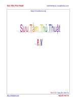
5. In the Expression section, type rotateY=sin(time);.
6. Click the Create button to add the expression to the antennaCtrl object (see Figure 5.51).
This expression creates a relationship where the rotation of the antennaCtrl group moves
back and forth over time. The sin function creates a smooth curve using time as the
input. The value of sin moves between -1 and 1. The value of the Rotate Y channel is
expressed in degrees, so this expression does not create a very visible motion. It oscillates
between -1 and 1 degrees. To fix this, you can add a multiplier to the expression.
When you click the Create button, Maya fills in the detailed path to the antennaCtrl chan-
nel. The original expression is replaced with antennaCtrl.rotateY=sin(time). As long
as an object is selected when you open the Expression Editor, you can type the name of the
channel, and Maya will understand that the channel is connected to the selected object.
Otherwise, you must specify the path to the channel by typing objectName.channelName.
Each statement in the expression should end with a semicolon.
7. In the Expression Editor, change the expression to read antennaCtrl.
rotateY=30*(sin(time));.
8. Click the Edit button to change the expression.
9. Rewind and play the animation. The antennae swing back and forth.
If you want the motion to move faster, create a multiplier for time. Change the expression so
that it reads antennaCtrl.rotateY=30*(sin(time*2));. This makes the rotation occur twice
as fast.
If you want to slow down the motion, multiply the time by a fraction. time*0.5 makes the
rotation move at half the original speed.
Figure 5.51
Enter an expres-
sion for the
antennaCtrl
curve in the
Expression Editor.
290
|
CHAPTER 5 anIMatIon teChnIques
You can add an expression to the Translate Y of the antennaCtrl group to make the antenna
move up and down:
1. Select the antennaCtrl, and open the Expression Editor (if it’s not still open).
2. In the Expression section, type translateY=cos(time); below the first expression (see
Figure 5.52).
3. Click the Edit button to create the expression.
This moves the antennaCtrl group up and down, making the antennae rotate upward
and downward (recall that the locators in the antennaCtrl group are aim locators for the
antennae geometry). The cos function (cosine) works like the sin function (sine) except
the cosine is the opposite of sine, so when sine is at -1, cosine is at 1, and vice versa.
To make the motion more interesting, you can add a noise function to each of the locators
in the antenna control group. The noise function creates a continuous random pattern
that moves between -1 and 1 (as opposed to the rand function, which creates a discon-
tinuous random motion between -1 and 1).
4. Select one of the yellow locators in the perspective view.
5. In the Channel Box, highlight the Translate Y channel, and choose Edit Expressions to
open the Expression Editor for the locator.
6. In the Expression section, type translateY=noise(time*4);. Then click the Create but-
ton to make the expression.
7. Play the animation; you’ll see the antenna move somewhat randomly.
8. Add a similar expression to the Translate Y of the other yellow locator. To make the
motion slightly different, try translate=noise(time*5);.
9. Save the scene as mechBugExpressions_v02.ma.
To see a version of the scene, open the mechBugExpressions_v02.ma scene from the chapter5\
scenes directory on the DVD.
Conditional Statements in Expressions
You can make expressions even more sophisticated by adding variables and conditional state-
ments. A simple conditional statement looks like this in the Expression Editor:
if (x is true){
Perform action;
}
else
{
Perform a different action;
}
Figure 5.52
Add the expression
for the Y transla-
tion as a second
line in the Expres-
sion Editor.
anIMatIon usIng exPressIons
|
291
There are other ways to state conditionals, but this is the most common and simplest way
to do it. To make the motion of the antennae more interesting, you’ll make the antennae move
faster when they are closer to the ground.
1. Continue with the scene from the previous section, or open the mechBugExpressions_
v02.ma scene from the chapter5\scenes directory on the DVD.
2. Select one of the yellow locators in front of the bug, and open the Expression Editor using
the Edit menu in the Channel Box.
To create a condition, you’ll make a variable that can hold a value. The value will be dif-
ferent depending on the outcome of the test performed by the conditional statement.
In this case, the variable can hold a value, which will be a multiplier for time in the
noise(time) statement applied to the locator’s Translate Y channel. Before you can use
the variable, you should declare it at the start of the expression. This lets Maya know
what type of data the variable will hold. In this case, the variable can be an integer (a
number without a decimal). The variable you will create is called $antSpeed, for antenna
speed. All variables must be preceded by a dollar sign.
3. In the Expression Editor, select the text, and press the Backspace or Delete key to clear the
Expression field. Type int $antSpeed; in the field.
4. Press the Return key (the Return key on the keyboard, not the Enter key on the numeric
keypad), and enter the following lines:
if (antennaCtrl.translateY<0){
$antSpeed = 10;
}
else
{
$antSpeed=2;
}
translateY = noise(time*$antSpeed);
Since the expression is testing to see the height of the antennaCtrl group, you need to
specify the path to the antennaCtrl group’s Translate Y channel. Expressions for channels
are self-contained, so unless you specify the path to another object’s channel, Maya won’t
understand what you’re talking about. Figure 5.53 shows the expression in the Expression
Editor.
5. Add the same expression to the other locator in the group. Use different values for the
$antSpeed variable so that the two antennae move in different ways.
6. Save the scene as mechBugExpressions_v03.ma.
To see a finished version of the scene, open the mechBugExpressions_v03.ma scene from the
chapter5\scenes directory on the DVD.
292
|
CHAPTER 5 anIMatIon teChnIques
Motion Path Animation
You can animate the movement of an object by attaching the object to a curve and then slid-
ing down the length of the curve over time. This is known as motion path animation. To create a
Motion Path, perform the following steps:
1. Open the mechBugPath_v01.ma scene from the chapter5\scenes directory on the DVD.
2. Turn on the grid display, and choose Create CV Curve Tool Options.
3. In the options, make sure Curve Degree is set to Cubic.
4. Draw a curve on the grid using any number of points; make sure the curve has some nice
twisty bends in it.
5. Right-click the curve, and choose Control Vertex.
6. Use the Move tool to move the CVs of the curve up and down so the curve is three-
dimensional (see Figure 5.54).
7. In the Outliner, select the mechanicalBug group, and Ctrl+click the curve.
8. From the Animation menu set, choose Animate Motion Paths Attach To Motion
Path Options.
Figure 5.53
Create a condi-
tional statement
as an expression to
make the antenna
move faster when
it’s closer to the
ground.
MotIon Path anIMatIon
|
293
9. In the options, choose Edit Reset to reset the options. Enter the following:
Set Front Axis to Z.
Turn on Follow.
Enable Bank.
Set Bank Limit to 30.
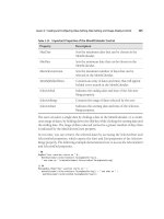
10. Click Attach to attach the bug to the curve (see Figure 5.55).
Figure 5.54
Draw and shape a
curve in the scene.
Figure 5.55
The options for Attach
To Motion Path
294
|
CHAPTER 5 anIMatIon teChnIques
The default Time Range is set to Time Slider so the bug will travel the length of the curve
based on the current length of the time slider (200 frames in this scene). You can change
this after the motion path is created.
The Follow option orients the animated object so the front axis follows the bends in the
curve. The Bank option adds a rotation on the z-axis around bends in the curve to simu-
late banking.
11. Play the animation. The bug follows the path (see Figure 5.56).
At this point, the animation looks a little silly; the other parts of the bug need to be animated,
which you can do using the techniques described in the chapter. By attaching the mechanical-
Bug group as opposed to the bodyCtrl group, you now have the option of adding animation to
the bodyCtrl curve to provide variation in the movement of the bug as it flies along the curve.
You can change the rate at which the bug flies along the curve by editing the motionPath1
node’s U Value attribute on the Graph Editor:
1. In the Outliner, select the mechanicalBug group.
2. In the Channel Box under Inputs, select motionPath1.
3. Choose Window Animation Editors Graph Editor to open the Graph Editor.
4. In the left column, select the motionPath1 U Value attribute, and press the f hot key to
focus the graph on its animation curve.
5. Use the graph-editing tools to edit the curve.
6. Save the scene as mechBugPath_v02.ma.
To see a version of the scene to this point, open the mechBug_v02.ma scene in the chapter5\
scenes directory on the DVD.
Figure 5.56
The bug is attached
to the motion path
curve. As the ani-
mation plays, the
bug travels along
the length of the
curve.
anIMatIng ConstraInts
|
295
Animating Constraints
You can constrain an object to more than one node. The weighting of the constraint strength can
be blended between the two nodes and even animated. This is a great technique for solving dif-
ficult animation problems, such as a character picking up and putting down an object.
Dynamic Parenting
Dynamic parenting refers to a technique in which the parenting of an object is keyframed. In this
exercise, you’ll animate the mechanical bug sitting on a moving object for a few moments before
flying off along a motion path.
This scene has the bug rigged and sitting at the origin of the grid. A cattail is bobbing up and
down in the breeze. Above the cattail, a curve defines a motion path (see Figure 5.57).
A locator named bugLanded is constrained to one of the joints of the cattail using a parent
constraint. On the motion path is another locator named bugFly. To make the bug sit on the
moving cattail, you’ll create a parent constraint between the bug and the bugLanded locator.
1. Open the mechBugConstrain_v01.ma scene from the chapter5\scenes directory on the DVD.
2. In the Outliner, select the bugLanded locator, and Ctrl+click the mechanicalBug group.
3. From the Animation menu set, choose Constrain Parent Options.
4. In the options, turn off Maintain Offset. Leave Translate and Rotate set to All.
5. Click Add to make the constraint (see Figure 5.58).
Figure 5.57
The scene con-
tains an animated
cattail and a
motion path.
Figure 5.58
The options for the
parent constraint
296
|
CHAPTER 5 anIMatIon teChnIques
The mechanical bug now appears on the end of the cattail. You can reposition the bug on
the cattail using the bodyCtrl and legCtrl curves.
6. In the Display Layers window, turn on the CONTROLS layer.
7. Select the blue bodyCtrl curve, and pull it upward to move the bug up above the end of
the cattail.
8. Turn on Wireframe view.
9. Select the red legCtrl circle, and move it upward with the Move tool so the legs are posi-
tioned on the end of the cattail. (Use the Show menu in the viewport to turn off the vis-
ibility of Joints so that you can easily see the geometry.)
10. Position each of the small purple leg control circles so the bug’s legs are posed on the end
of the cattail geometry (see Figure 5.59).
11. Play the animation. You’ll see the bug sticking to the cattail as it moves up and down.
12. Set the timeline to frame 320.
13. In the Outliner, select the bugFly locator, and Ctrl+click the mechanicalBug.
14. Create another parent constraint; the same options should be applied automatically when
you create the constraint.
When you play the animation, you’ll see that the bug is floating between the two loca-
tors, thus inheriting a blend of their animation. This is because the strength of both con-
straints is at 1 (or full strength).
15. Set the timeline to frame 353. This is a point where the two locators are very close and a
good time for the bug to start to fly off.
Figure 5.59
Pose the legs using
the legCtrl curves
so the bug is stand-
ing on the cattail.
anIMatIng ConstraInts
|
297
16. In the Outliner, expand the mechanicalBug group. Select the mechanicalBug_parent-
Constraint1 node.
17. In the Channel Box, set Bug Fly W1 to 1 and Bug Landed W0 to 0. The bug reorients itself
to match the orientation of the bugFly locator.
18. Shift+click both the Bug Landed W0 channel and the Bug Fly W1 channel in the Channel
Box (see Figure 5.60). Right-click, and choose Key Selected.
19. Set the timeline to 347.
20. Reverse the values of the two weights so Bug Landed W0 is at 1 and Bug Fly W1 is at 0.
21. Set another keyframe.
22. Rewind and play the animation. You’ll see the bug sitting on the cattail as it bobs up and
down. At frame 347, the bug switches to the motion path and flies off.
23. With the mechanicalBug parentConstraint1 node selected, open the Graph Editor.
24. Select the Bug Landed W0 and Bug Fly W1 channels on the left column of the Graph
Editor, and press the f hot key to focus on their animation curves.
25. Use the curve-editing tools to fine-tune the animation so the transition between the cat-
tail and the motion path is smoother. This usually takes a fair amount of experimentation
(Figure 5.61).
26. Save the scene as mechBugConstrain_v02.ma.
Figure 5.60
Set the weights
of the parent con-
straint and key it
at frame 353.
298
|
CHAPTER 5 anIMatIon teChnIques
In some cases, you can create a smoother transition by extending the length of time between
the keyframed weight values. It depends on what type of motion you are trying to achieve and
your own personal taste.
As shown in the mechBugConstrain_v02.ma scene from the chapter5\scenes directory on
the DVD, you can also animate the bodyCtrl curve and the leg controls to create a more believ-
able motion to the bug as he takes flight.
Animation Layers
Animation layers separate the keyframe data applied to objects in the scene so you can create
variations of animation for approval from a director, blend different versions of an animation
together for a higher level of control, or organize the animated parts of an animation. This sec-
tion is a tour of how animation layers work and some of the ways they can be applied in a scene.
There is a great amount of flexibility in how animation layers can be used; no doubt you will
create your own preferred animation layer workflow after a little bit of practice.
Creating an Animation Layer
In this section, you’ll create a simple dancing motion for the mechanical bug. Animation layers
take some getting used to, so you’ll start with a very simple animation.
1. Open the mechBugLayers_v01.ma scene from the chapter5\scenes directory on the DVD.
2. Set the current frame on the timeline to 1.
3. Select the blue bodyCtrl curve above the bug, and set its Translate Y channel to -0.5.
4. Create a keyframe for this channel.
5. Set the current frame to 20, set Translate Y to 0.5, and create another keyframe.
Figure 5.61
Edit the weights
of the constraint
on the Graph
Editor.
anIMatIon layers
|
299
6. Create three more keyframes for the bodyCtrl curve:
Frame 40 Translate Y: -0.5
Frame 60 Translate Y: 0.5
Frame 80 Translate Y: -0.5
When you play the animation, the bug bobs up and down.
7. In the Layer panel in the lower-right corner of the screen below the Channel Box, set Mode
to Anim. This switches the Layer Editor to Animation layers as opposed to Display or
Render layers.
8. Choose Layers Create Empty Layer. Two layers appear. The new layer is AnimLayer1,
and the default Base Animation layer is at the bottom.
In the perspective view, nothing has changed regardless of which layer is selected.
9. Double-click AnimLayer1, and rename it bounce (see Figure 5.62).
10. Select the bodyCtrl curve.
11. In the Animation Layer panel, select the bounce layer, RMB+click it, and choose Add
Selected Objects. This adds just the bodyCtrl curve.
Notice that all the channels in the Channel Box are now yellow. You’ll also notice that in
the INPUT section under the Channel Box for the bodyCtrl curve, bounce has been added
to the list of inputs.
When creating an animation layer, you have the option of creating the layer from selected
objects in the scene or copying an existing layer (using the options in the Layers menu).
When you copy a layer, the keyframes are also copied to the new layer. The Layers menu
has a lot of options you’ll explore as you go through the next few exercises.
12. Select the bounce layer, and a green circle appears on the right. This indicates that the
layer is active.
13. Play the animation. It looks the same as before. Notice that there are no keyframe tick
marks on the timeline.
14. Select the BaseAnimation layer; the tick marks reappear. So, what does this mean?
Each layer has its own set of keyframes for the objects in that particular layer. The bounce
layer has no keyframes yet, so what you’re seeing when you play the animation is the
keyframes set on the BaseAnimation layer. The way in which the keyframes on one layer
interact with the keys on another depends on the layer’s Mode and Accumulation settings.
Figure 5.62
Create a new ani-
mation layer in the
scene, and rename
it bounce.
300
|
CHAPTER 5 anIMatIon teChnIques
You can also choose Layers Selected Objects to create a new layer based on the selected
objects. The keyframes set on the object are removed from the current selected layer and added
to the new layer created from the Extract operation.
Layer Mode
The mode of a layer can be either Additive or Override. Additive layers blend the values of the
keys together so the resulting animation is a combination of the two layers. Using the Additive
mode, you can add changes to the animation without affecting the original keyframes on the
BaseAnimation layer.
When a layer is set to Override mode, the animation on that layer overrides the animation
on the layers below it. Override mode is a good way to create different “takes” or versions of an
animation without affecting the original BaseAnimation layer.
Follow the next steps to see how these modes work:
1. In the Layer Editor, select the bounce layer.
2. Choose (from the menu in the Layer Editor) Layers Layer Mode Override. When you
play the animation, the bug no longer moves.
If you switch to the BaseAnimation layer, you can see the keyframes on the timeline, but
the bug still doesn’t move. This is because even though the bounce layer is not selected, it
is overriding the BaseAnimation layer.
3. In the Layer Editor, click the Mute Layer button to the left of the ghosting icon (the
ghost icon looks like a little man on a red background) button on the Bounce layer (see
Figure 5.63). The Mute Layer button temporarily disables the layer; when you click Play,
you’ll see the bug move up and down again.
4. Turn the Mute Layer button off, and then play the animation. The bug should stop
moving.
5. Select the bounce layer, and drag the Weight slider slowly to the left as the animation
plays (see Figure 5.64).
As you drag the Weight slider down, the influence of the overriding layer decreases, and
you can see the bug start to move up and down again. When the weight is at zero, the
overriding layer has no more influence. The K button to the right of the Weight slider sets
a keyframe on the Weight value so you can animate the strength of the weight over time.
Figure 5.63
The Mute Layer
button temporarily
disables a layer.
Figure 5.64
The Weight slider
determines the
amount of influence
the layer has over the
animation.
anIMatIon layers
|
301
6. Select the bounce layer.
7. Set the Weight for the bounce Layer to 1, and make sure the layer is not muted. When you
play the animation, you should see no motion.
8. Select the bodyCtrl curve, and set the following keyframes on the Translate Y channel.
Frame 1 Translate Y: -0.05
Frame 10 Translate Y: 0.5
9. With the bodyCtrl curve selected, open the Graph Editor, and select the Translate Y channel.
10. Drag a selection around the keys, and choose Curves Post Infinity Oscillate.
When you play the animation, the bug bounces a little faster. As you lower the Weight
setting for the layer, you’ll see the slower bouncing motion of the BaseAnimation layer.
If you turn off the Passthrough option in the Layers Layer Mode menu, the animation
of the lower layers does not pass through the upper layers, so as you lower the Strength
value, you’ll see the bouncing stop as the Weight value approaches 0.
11. Set Layer Mode to Additive, as shown in Figure 5.65.
12. Set the Weight setting of the bounce layer to 1, and play the animation.
You can see that the resulting animation is now a combination of the keyframe values on
the bounce and BaseAnimation layers (the Passthrough option has no effect on additive
layers).
When the mode is set to Additive, the keyframe values from the top layer are added to
the layers below; in this case, the values of the Bounce layer are added to the values in the
Base Animation layer. As you alter the weight slider for additive layers, this decreases the
layer’s keyframe values. Keep in mind that the layer only affects the keyframe values of
the objects that it contains.
13. In the Options menu of the Layer Editor, choose the Turn On Ghosts Manually option.
14. Click the ghosting icon (looks like a little man on a red background) in the Base
Animation layer. This creates a ghost of the animated objects on this layer so you can
compare it with the animation on other layers. In this case, you’ll see a red copy of the
bodyCtrl curve moving according to the keyframes set on the BaseAnimation layer. The
icon switches so that you’ll see two men on the button. One represents the ghost of the
other.
15. Rewind the animation, and select the bodyCtrl curve.
16. In the Layer Editor, choose Create Layer From Selected. Name the new layer rock, and set
its mode to Override.
Figure 5.65
When Layer Mode
is set to Additive,
the animation of
the two layers is
combined.
302
|
CHAPTER 5 anIMatIon teChnIques
17. Select the rock layer. In the Channel Box, highlight the Rotate X, Y, and Z channels, and
set a keyframe on these channels.
18. Turn on the Auto Keyframe feature by clicking the key icon to the right of the timeline.
19. Set the timeline to various points in the animation, and use the Rotate tool to rotate the
bug, making him do a happy little dance.
20. Rewind and play the animation. You’ll see him move around.
Experiment with the weight of the rock layer; try setting its mode to Additive, and
observe the result.
By varying the weight, you get a pretty good dancing action (for a mechanical bug) fairly
easily.
21. Save the scene as mechBugLayers_v02.ma.
To see a version of the scene to this point, open the mechBugLayers_v02.ma scene from the
chapter5\scenes folder on the DVD.
Use Animation Layers for Driven Keys
Layers can be created for other types of keyframe animation such as driven keys. For instance,
you can create a layer where driven keys make the legs of the bug appear to crawl forward as the
bodyCtrl moves along the z-axis and then a second layer where a new set of driven keys makes the
bug appear to crawl sideways as the bodyCtrl moves along the x-axis.
Other Options in the Layer Editor
The Layer Editor includes other options as well:
Lock Layer Click the padlock icon to the left of the layer. When this is active, you cannot
add keyframes to the layer. This is helpful if you use Auto Keyframe because it prevents you
from accidentally changing the animation on a layer.
Solo Layer Click the horizontal bar icon to left of the layer. This temporarily disables the
animation of other layers so you can focus on just the soloed layer (more than one layer can
be in solo mode).
Mute Layer This button disables animation on the selected layer.
Ghost Layer This button creates a ghost of the animated objects on the layer. You can
change the color of the ghost by right-clicking the ghosting button and choosing a color from
the pop-up window.
Zero Key Layer The Zero Key Layer is a way to edit a small portion of an animation using
an animation layer. Select an object in the layer, and click the Zero Key icon in the upper left
of the Layer Editor to create a starting point on the timeline for the edit. Then move the Time
slider to a later point in the animation, and click the Zero Key icon again. Any keyframes
you set on the object between these two points in time will not be offset from the original
animation.
anIMatIon layers
|
303
You can change the order of layers by clicking the up and down arrows in the upper right of
the Layer Editor window. The order of layers affects how the animation behaves. For instance,
an override layer overrides animation on the layers below it but not above it. You can stack addi-
tive layers above, and Override Layer adjusts their weighting and rearranges their order to cre-
ate different variations on the animation.
The Layer Accumulation settings under Layers Scale Accumulation determine how scaling
and rotation are calculated when two or more layers that have animated scaling and rotation are
combined.
The animated scaling on two layers can be added or multiplied depending on the Layer
Accumulation setting.
Euler and quanternion are two different methods for calculating rotation. Euler is the stan-
dard method used in Maya. If the combination of rotation animation on two different layers
leads to an unexpected result, try switching to quanternion in the Layer Accumulation settings.
Euler vs. Quanternion Rotation
Euler rotation is calculated based on three angle values (X, Y, and Z) plus the order in which the
angles are calculated. This is the standard method for calculating rotation in Maya, and it works
in most cases. Euler rotation is prone to the problem of Gimbal Lock, where two of the axes overlap
and lead to the same result.
Quanternion rotation uses a more complex algorithm that helps it avoid Gimbal Lock problems. When
Rotation is set to Quanternion, Maya calculates the animation of rotation by using the X, Y, Z anima-
tion curves to create a fourth curve (W), which represents the rotation in quanternion units.
Layer Hierarchy
You can create a hierarchical relationship between animation layers. This is useful as an organi-
zational tool and can speed up your workflow as you animate. Creating a hierarchy means par-
enting one or more animation layers to another. When you mute or solo the parent layer, all the
child layers are also muted or soloed. Likewise, the Weight and Mode settings of the parent can
affect the child layers. When animation layering becomes complex, you can use the hierarchy to
quickly enable, disable, and rearrange the layers.
1. Continue with the scene from the previous section, or open the mechBugLayer_v02.ma
scene from the chapter5\scenes folder on the DVD.
2. In the Animation Layer Editor, mute the rock and bounce layers. You’ll notice that the
bug still bounces. This is because of the keyframes set on the BaseAnimation layer.
3. Before creating a hierarchy for the layers, you can quickly move the animation on the
BaseAnimation layer to its own new layer.
a. Select the bodyCtrl curve and the BaseAnimation layer.
b. Right-click the BaseAnimation layer.
c. Choose Extract Selected Objects.
304
|
CHAPTER 5 anIMatIon teChnIques
Extracting the bodyCtrl object from the BaseAnimation layer creates a new animation
layer that contains the bodyCtrl curve and its animation. At the same time, the keyframes
from the bodyCtrl curve are removed from the BaseAnimation layer. If you mute all the
layers except BaseAnimation, the bug no longer moves when you play the animation.
4. Name the new layer bounce1, and rename bounce as bounce2.
5. Make sure bounce1 is below bounce2. Mute all the layers (see Figure 5.66).
6. In the Layer Editor, choose Layers Create Empty Layer. Name the new layer legAnim.
7. Select the circle under the front left leg.
8. In the Layer Editor, choose Layers Create From Selected. Name the new layer
FLeftLegAnim.
9. MMB-drag FLeftLegAnim on top of the legAnim layer to make it a child of this layer. A
small black triangle appears, and the FLeftLegAnim layer is indented above the legAnim
layer (see Figure 5.67).
10. Repeat steps 7 through 9 for the front right leg circle. Name the new layer
FRightLegAnim.
11. Select the FLeftLegAnim layer, and in the perspective view, select the circle under the
front left leg.
12. In the Channel Box, Shift+click all the channels except the Translate channels.
13. Right-click, and choose Remove From Selected Layers (see Figure 5.68).
14. With the FLeftLegAnim layer selected, set a keyframe on the left leg control circle’s
Translate channels. Then use the Auto Keyframe feature to create an animation of the
leg moving up and down as if it’s tapping out a little beat.
Figure 5.66
Copy the Base-
Animation layer,
renamed it bounce1,
and move it below
the other layers.
Mute all layers.
Figure 5.67
The FLeftLegAnim
layer is parented to
the legAnim layer.
anIMatIon layers
|
305
15. Switch to the FRightLegAnim layer, and create a similar animation for the front right leg.
16. When you have a nice animation going for both layers, unmute the other layers, and play
the animation.
17. Click the black triangle on the legAnim layer to collapse the layer.
Experiment with the Weight setting of the legAnim layer. The Weight value of the parent
layer applies to both child layers as well. This is also true for the Layer Mode, Mute, and
Solo settings.
18. Save the scene as mechBugLayers_v03.ma.
You can create further nested layers within the hierarchy. Each child layer can have its own
Mode setting. To keep things simple, you can use empty layers as parent layers. The empty par-
ent layers can be used to set the Weight and Mode operations of the child layers. If the parent
layer is empty, you don’t have to worry about how the animation in a parent layer is blended
with the child layers.
To see a version of the scene to this point, open the mechBugLayers_v03.ma scene from the
chapter5\scenes folder on the DVD.
Merging Layers
You can merge the animation of two layers into a single animation layer.
1. Continue with the scene from the previous section, or open the mechBugLayers_v03.ma
scene from the chapter5\scenes folder on the DVD.
Figure 5.68
Remove the Rotate
and Scale channels
from the anima-
tion layer.
306
|
CHAPTER 5 anIMatIon teChnIques
2. In the Animation Layers Editor, Shift-select the bounce2 and bounce1 layers.
3. Choose Layers Merge Layers Options.
4. In the options, set the Merge To option to Bottom Selected Layer.
5. Set Layers Hierarchy to Selected and Result Layer Mode to Additive.
6. Turn on the Smart Bake option.
When you merge two or more layers, the animation of the objects on the layers is baked.
You can choose to sample the baked keyframes based on the Sample By value. For instance,
if you set Sample By to 1, then the object on the resulting baked layer will have a keyframe
placed on the animated channels for every frame of the animation. A setting of 2 creates
a key on every other frame. The Smart Bake option creates a curve from the combined
animation layers with fewer keyframes. The Increase Fidelity setting increases the accu-
racy of the resulting animation curve to better represent the combined animation of the
two layers. The Sample By option is more accurate but creates a lot of keyframes, which
can be hard to edit. The Smart Bake option works very well when there are fewer layers
or the animation is simple.
You can bake a parent layer and all its child layers into a single layer. You can also choose
to delete the original layers or keep them. Figure 5.69 shows the options for merging
layers.
7. Click Apply to merge the layers. A new layer named Merged Layer is created. Rename the
new layer bounce.
8. Select the bounce layer.
9. In the perspective view, select the bodyCtrl, and open the Graph Editor. You’ll see the
merged animation curve in the Graph Editor (see Figure 5.70).
10. Save the scene as mechBugLayers_v04.ma.
To see a version of the scene, open the mechBugLayers_v04.ma scene in the chapter5\scenes
folder on the DVD.
Figure 5.69
The options for
merging layers
the BottoM lIne
|
307
Camera Sequencing
Maya 2011 introduces the Camera Sequencer, which gives you the ability to plan and test your shots
before you render. For more information on these tools, refer to the CameraSequencer.mov movie
file included in the BonusMovies folder on the DVD.
The Bottom Line
Use Inverse Kinematics Inverse Kinematics creates a goal object, known as an End Effector,
for joints in a chain. The joints in the chain orient themselves based on the translation of the
goal. The IK Handle tool is used to position the End Effector.
Master it Create an Inverse Kinematic control for a simple arm.
Animate with keyframes A keyframe marks the state of a particular attribute at a point
in time on the timeline. When a second keyframe is added to the attribute at a different point in
time, Maya interpolates the values between the two keyframes, creating animation. There are
a number of ways to edit keyframes using the timeline and the Channel Box.
Master it Create a number of keyframes for the Translate channels of a simple object.
Copy the keyframes to a different point in time for the object. Try copying the keyframes
to the Scale channels. Try copying the keys to the Translate channels of another object.
Use the Graph Editor More sophisticated animation editing is available using the anima-
tion curve editing tools on the Graph Editor.
Master it Create a looping animation for the mechanical bug model using as few keys
as possible. The bug should leap up repeatedly and move forward with each leap.
Figure 5.70
The merged ani-
mation curve is
displayed in the
Graph Editor.
308
|
CHAPTER 5 anIMatIon teChnIques
Preview animations with a playblast A playblast is a tool for viewing the animation as a
flip book without having to actually render the animation. FCheck is a utility program that is
included with Maya. Playblasts can be viewed in FCheck.
Master it Create a playblast of the mechBugLayers_v04.ma scene.
Animate with expressions Expressions are a powerful way to automate the movement of
an object. Using conditional statements, you can create an expression that causes the anima-
tion to react to changes in the scene automatically.
Master it Create an expression to randomly rotate the bug’s eyes up and down. Make
the rotation faster based on the height of the bodyCtrl curve.
Animate with motion paths Motion paths allow you to attach an object to a curve. Over
the course of the animation, the object slides along the curve based on the keyframes set
on the motion path’s U Value.
Master it Make the bug walk along a motion path. See whether you can automate a
walk cycle based on the position along the path.
Use animation layers Using animation layers, you can add new motion that can override
existing animation or be combined with it.
Master it Create animation layers for the flying bug in the mechBug_v08.ma scene in the
chapter5\scenes directory on the DVD. Create two layers: one for the bodyCtrl curve
and one for the legsCtrl curve. Use layers to make the animation of the wings start with
small movements and then flap at full strength.
Chapter 6
Animating with Deformers
As you learned in Chapter 1, objects in a Maya scene have both a transform node and a shape
node. The transform node contains data concerning where the object is in a scene, its orienta-
tion, and its scale. The shape node contains data about the form of the object. If you want to
animate an object moving around in a scene, usually you’ll keyframe the translation, rotation,
and scale of the transform node. If you want to animate the shape of an object, such as the facial
expressions of a character, you want to use a deformer, which is a type of animation control
applied to the shape node of an object.
Deformers are extremely versatile, and they can be used for both modeling and animation
and as part of an animation rig. Deformers come in many forms. Blend shapes are used to inter-
polate between variations of a shape’s form and are most commonly used to create expressions
for characters. Lattices are a cage of points that surround a shape, allowing you to indirectly
reshape a form to create smooth deformations. Clusters are used to animate a shape’s vertices
or groups of vertices easily. Nonlinear deformers create broad shape changes that can be used for
cartoonish effects such as squashing and stretching. Jiggle deformers are a simple way to apply
secondary jiggling effects to a shape.
In this chapter, you’ll see some of the ways to animate geometry using deformers. From cre-
ating facial expressions to animating a jellyfish, you can apply deformers in thousands of ways
to bring your creations to life.
In this chapter, you will learn to:
Animate facial expressions
•u
Create blend shape sequences•u
Deform a 3D object•u
Animate nonlinear deformers•u
Add jiggle movement to an animation•u
Animating Facial Expressions Using Blend Shapes
As the name suggests, a blend shape deformer blends, or interpolates, between variations of a
geometric form. A blend shape deformer uses one or more blend shape targets. These targets
are duplicates of the original model that have been modified using a variety of modeling
techniques.
Animating facial expressions for characters is usually accomplished through the use of blend
shapes. Although this is not the only way to animate expressions and speech, it is the most com-
mon because it is relatively straightforward to set up and animate. In this section, you’ll learn
310
|
CHAPTER 6 anIMatIng WIth deForMers
how to create blend shape targets, paint blend shape weights, create a blend shape deformer, and
build a simple facial animation rig.
You create the blend shape deformer by selecting the targets and the original model and
choosing Create Deformers Blend Shape. The deformer controls consist of sliders—one for
each blend shape target. The original model is animated by moving and keyframing the sliders.
As the value of a slider moves between 0 and 1, Maya interpolates the change, blending between
the original shape and the target shape. The duplicate model is known as the blend shape target,
and the original model is known as the base mesh.
You should understand a few things about how blend shapes work before you set up a facial
animation rig. First, blend shapes always move in a straight line when interpolating the change
between the original model and the blend shape target. Think of how your eyelids move when
you blink. Your eyelid is a flap of skin that moves over the spherical shape of your eyeball. If you
make a dot on the edge of your eyelid with a marker (don’t do this—just imagine it) and then
follow the path of that dot from a side view, the dot moves in an arc as your eyelid closes.
If you have a model of a face with the eyes open and a blend shape target with the eyes
closed, when you create the blend shape deformer and then animate the eyes closing, instead
of moving in an arc, the eyelids will move in a straight line from the open position to the closed
position. Most likely the eyelid geometry will pass through the eyeball geometry, creating a
less-than-convincing blinking behavior (see Figure 6.1). Understanding that the blend shape
deformer moves in a linear direction from one state to the next is important if you are to develop
a solution for this problem.
Second, a blend shape target should have the same number of vertices and the same point order
as the original geometry. Vertices on polygons and control vertices (CVs) on NURBS geometry are
numbered in a specific order. You can see the numbers listed in the Script Editor when the vertices
are selected. If the number of points and the order of the points on a blend shape target do not
match the original, the deformer will not be created, or it will behave strangely (see Figure 6.2). It
is possible to use a blend shape target that has a different number of vertices than the base mesh;
however, this can lead to some unpredictable results.
Figure 6.1
Blend shape defor-
mations move in
a straight line,
which can cause
problems for cer-
tain types of facial
movements, such
as blinking eyelids.