Mastering Autodesk Maya 2011 phần 5 ppt
Bạn đang xem bản rút gọn của tài liệu. Xem và tải ngay bản đầy đủ của tài liệu tại đây (3.49 MB, 105 trang )
skInnIng geoMetry
|
391
Broken-Joint Skeletons
Keep in mind that you also have the option of binding only selected joints. In some circumstances,
this can be quite useful. For example, if you set up what is known as a broken-joint skeleton, which
uses additional bones outside the main skeleton hierarchy as deformers, these additional joints are
usually constrained to the main hierarchy using parent constraints. By using parent constraints,
the joints “float” outside the main hierarchy, giving them a level of freedom of movement to create
special deformation effects. (Sometimes floating joints are used for facial animation instead of or in
addition to blendshape deformers.) When skinning a broken rig to the skeleton, select the floating
joints along with the joints in the main hierarchy when the smooth bind operation is performed.
The following are the relevant settings:
Bind method The bind method determines how joints influence vertices, by either fol-
lowing the skeleton’s hierarchy or simply using whichever joint is the closest. The hier-
archy of the giraffe is complete and calls for every bone to be weighted; however, for the
tips, use Closest In Hierarchy.
Include method The include method dictates which vertices are included in the initial
volumes. Your options are Closest Volume and Minimum Weight. Choosing Minimum
Weight opens an additional option to set the length of the volume. By default this is .25,
causing each volume to be 25 percent longer than the bone to which it is attached. Most
characters will have a different area of influence based on its location. For instance, the gi-
raffe’s knee needs to have a smaller falloff compared to the torso. Choose Closest Volume.
There are two types of volumes you can use, a cylinder or a capsule:
A cylinder will deliver a hard edge.
•u
The capsule is rounded at its ends, providing a smoother falloff. •u
Keep the capsule turned on.
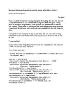
Skinning method The skinning method has the greatest impact on your bind. You can
use Classic Linear, Dual Quaternion, or a blend of both.
Dual Quaternion provides the most suitable deformations for realistic characters. It
•u
preserves the volume of a mesh when a joint is twisted or rotated.
Classic Linear does not preserve volume and produces a visible shrinking of the
•u
geometry.
Take a look at Figure 7.34 to see the differences between the two.
The last two settings relate to how many influences a single vertex can have. It is important
to remember that joints are not the only nodes that can be bound to geometry. Other geom-
etry can also be used and is therefore considered an influence as well. Most weighted
objects do not require more than four influences per vertex, which is Maya’s default. In
addition, a lot of game engines have a hard limit of four influences on a single vertex. After
binding, you can keep the influences locked to four by selecting Maintain Max Influences.
392
|
CHAPTER 7 rIggIng and MusCle systeMs
This is particularly useful when weighting geometry for an environment outside of Maya,
such as a game engine. Keep the default settings for the giraffe (see Figure 7.35).
4. Choose Bind Skin.
Keep in mind that all the weighting can be altered after the bind has been applied.
These settings merely give you a place to start and typically require a lot of fine tuning.
Furthermore, you can change these settings through the skinCluster node that is attached
to the bound geometry (see Figure 7.36).
Figure 7.34
The Classic Linear
skinning method
is applied to the
joints on the left
and Dual Quater-
nion on the right.
Figure 7.35
Bind the giraffe
geometry to its
skeleton.
Figure 7.36
The skinCluster
node holds all the
settings from the
initial binding
options.
skInnIng geoMetry
|
393
The giraffe’s initial bind is established; now it’s time to finetune its weighting. Traditionally,
modifying weighted geometry has been like feeling your way around in the dark. Maya’s
interactive skin tool not only sheds light on each and every vertex but does so with preci-
sion and ease of use. The Interactive Skin Bind tool allows you to quickly massage the
weights to an acceptable level.
5. Start with the giraffe’s front legs to get used to the controls. Select L_upperarm_jnt. If
it isn’t active already, choose Skin Edit Smooth Skin Interactive Skin Bind Tool. By
default two volumes are displayed. The only interactive one is the volume on the selected
joint. The second volume is a reflection that is attached to r_upperarm_jnt. The reflection
is displayed based on the reflection tool settings and operates the same way as it does
with the transformation tools (see Figure 7.37).
Figure 7.37
The interactive vol-
umes are reflected
by default.
394
|
CHAPTER 7 rIggIng and MusCle systeMs
Each volume can be translated, rotated, and shaped. A heat-style color graph is used to
illustrate the joint’s influence, with red being the highest amount of influence and blue
being the least. A few color presets are provided along with the ability to change the color
graph any way you would like.
The capsule’s manipulator is also color coded. Red, green, and blue are used to repre-
sent the three axes, respectively. Depending on which part of the manipulator you grab,
the shape of the capsule is altered. For the most part, each axis scales the selected ring
uniformly.
6. Use the LMB and grab the top, red, horizontal ring.
7. Resize it to decrease the amount of influence.
8. Repeat this operation for the lower ring.
9. In addition to changing the capsule’s shape, you can also use the traditional Move And
Rotate manipulator (scale is based on the volume) to fit the capsule better to the geom-
etry. The manipulator is located in the center of the capsule. Looking at the front of
the giraffe, translate and rotate the capsule for a better fit. Do the same for its profile.
Figure 7.38 shows the adjusted capsule.
Figure 7.38
Translate and
rotate the capsule
to encompass the
leg geometry.
skInnIng geoMetry
|
395
10. Visible interactivity has been limited so far because the giraffe is in its original bind pose
position. Translate the leg 1.0 in the Z and 0.5 in the Y.
11. Select l_upperarm_jnt. Notice that the geometry in the middle of the bone appears to be
sagging (Figure 7.39). This is an indication that the geometry is not weighted to 1 at those
particular vertices. However, the heat map shows full influence. Use the up arrow to go to
the preceding joint, L_shoulder_jnt.
12. L_shoulder_jnt overlaps the L_upperarm_jnt, obviously causing the problem. Use the
down arrow to return to L_shoulder_jnt.
Maya is displaying the non-normalized weight of the joint; therefore, the color displayed
is red. What you are actually seeing is the combined weight value of both joints.
13. In the tool settings for Interactive Skin Bind, find Display Weights. It is located above the
color graph. Change it to Normalized. You can now see the true weight value of the joint.
14. Use the up arrow to go back to L_shoulder_jnt.
Figure 7.39
The geometry in
the middle of the
bone is sagging
even though the
volume shows the
hottest influence.
396
|
CHAPTER 7 rIggIng and MusCle systeMs
15. Modify the volume to fit its bone better. You can hold Shift while moving the red rings
to uniformly scale the entire volume. If you hold Shift while adjusting the green or blue
rings, the effects are local to that ring. Figure 7.40 shows the results of the new volume
shape.
16. Save the scene as giraffe_v12.ma.
To see a version of the scene, open the giraffe_v12.ma scene from the chapter7\scenes
directory on the DVD.
Painting Skin Weights
The Interactive Skin Bind tool takes you really far into the weighting process. However, the
weights still need work. To make the skin move properly, you need to edit the weight values of
the vertices; this can be done with the Paint Weights tool. To maximize the benefits of painting
Figure 7.40
Modifying the
L_shoulder_jnt’s
volume fixes the
upper arm.
skInnIng geoMetry
|
397
weights, your geometry should have good UVs. These are explained in Chapter 11. This exercise
demonstrates techniques for painting weights on various parts of the giraffe:
1. Continue with the scene from the previous section, or open the giraffe_v12.ma scene
from the chapter7\scenes directory on the DVD.
2. Move the giraffe leg up again to interactively see the effects of painting weights.
3. Translate the leg 1.0 in the Z and 0.5 in the Y.2.
4. In the viewport, switch to smooth-shaded mode (hot key = 6).
5. Select the giraffe geometry, and choose Skin Edit Smooth Skin Paint Skin Weights
Tool. Make sure the Tool Options window is open.
The geometry turns black except for the area around the joint listed in the Influence sec-
tion of the Paint Skin Weights Tool window. The geometry is color coded.
White indicates a joint weight value of 1 (100 percent).
•u
Black indicates a joint weight value of 0. •u
Shades of gray indicate values between 0 and 1 (see Figure 7.41). •u
You can also switch to use the same gradient color ramp used in the Interactive Skin
Bind tool.
Figure 7.41
The Paint Skin
Weights tool color
codes the geom-
etry based on the
amount of weight
influence each joint
has for each ver-
tex of the skinned
geometry.
398
|
CHAPTER 7 rIggIng and MusCle systeMs
The Paint Skin Weights tool uses the Artisan brush interface. As you paint on the model,
the operation selected in the Paint Weights section determines how the brush edits the
weights. You can replace, add, smooth, or scale weights in the areas you paint on the
model. The easiest way to approach weight painting is to stick to only the Add and
Smooth operations.
Each vertex on the model receives up to a value of 1 from all the joints on the model. The
total weight values must equal 1, so if a selected vertex receives a value of 0.8 from a par-
ticular joint, the remaining weight value (0.2) must come from another joint in the chain.
Usually this remaining weight value comes from a joint close by the vertex as determined
by Maya. This is where things can get tricky. If you paint on a vertex using the Replace
operation with a value of 0.5 for a particular joint, the remaining 0.5 weight value is distrib-
uted among the other joints in the chain, which can lead to some strange and unpredict-
able results. If instead you use the Add operation with very low values, you can carefully
increase a joint’s influence over a vertex without worrying about Maya assigning the
remaining weight values to other joints in the chain.
6. The area you want to paint is the armpit of the front left leg. To expedite the process, force
the Paint Weights tool to only display the joints you want to paint influence for. To do this,
hold Ctrl and pick each joint you want to work with in the Influences section of the Paint
Weights tool. You can also use Shift to select the first and last joints to highlight a group.
7. With your joints selected, click the tack icon in the upper-right corner of the Influences
section (see Figure 7.42).
8. Choose L_upperarm_jnt from the influences.
9. Set Paint Operation to Replace and Value to 0.0.
10. Paint the area being pulled by the arm that belongs to the torso. To resize your brush, use
the b key. Use Figure 7.43 for reference.
11. Once you have separated the torso skin from arm skin, use the Smooth operation to clean
the weights.
The giraffe has a bone jutting out in this location. A lot of the weights are still being used
by the torso.
Figure 7.42
Reduce the num-
ber of joints dis-
played in the Paint
Weights tool by
pinning them.
skInnIng geoMetry
|
399
12. Set the paint value to 0.1.
13. Use the Add operation to move the weights more onto the upper arm.
14. When finished, go back over it with the Smooth operation again. Figure 7.44 shows the
progress so far.
Figure 7.43
Paint a weight of
0 to remove the
influence of the
arm.
Figure 7.44
The skin weight-
ing has been
smoothed.
400
|
CHAPTER 7 rIggIng and MusCle systeMs
There are still a few vertices that are being unruly.
15. Change Paint Tool Mode to Select, and choose two or three of the worst vertices. You can
also choose Paint Select.
Toward the top of the Paint Skin Weights window is a Tools section. The middle icon is
the Weight Hammer tool. This tool assigns an average of the weights around the selected
vertices. Figure 7.45 shows the same area from Figure 7.44 after the Weight Hammer tool
was applied.
16. You can continue to paint the skin weights with the joints posed. This is an excellent way
to get visual feedback as you edit the weights.
17. Save the scene as giraffe_v13.ma.
To see a version of the scene to this point, open the giraffe_v13.ma scene from the chapter7\
scenes directory on the DVD.
Figure 7.45
The skin weights
have been cleaned
up with the Weight
Hammer tool.
skInnIng geoMetry
|
401
Editing Skin Weights in the Component Editor
In some cases, you may want to edit the skin weights by entering a precise numeric value.
To do this, follow these steps:
1. Switch to component mode, and select the vertices you need to edit directly.
2. Choose Window General Editors Component Editor.
3. On the Smooth Skins tab, you’ll see a spreadsheet that lists each joint’s influence for each
of the selected vertices (Figure 7.46). You can change these values by directly entering
numbers into the spreadsheet.
Remember that each vertex must have a total weight value of 1, so if you set a value lower
than 1, the remaining value will be assigned to a different joint. You can turn on the Hold option
to lock a vertex’s weight value so Maya will not change the value automatically.
Copying Skin Weights
You can copy the weights from the low-resolution model to the high-resolution model. It does
not matter that the vertices do not perfectly match because the overall weighting can easily
be transferred. This reduces the difficulty of editing the initial weights on the high-resolution
model.
Copying weights is extremely useful when you have a lot of characters to weight. Once
you are happy with one character, you can copy its weights onto another character, even if the
dimensions are not the same. The Copy Weights tool copies weighting information based on
proximity. As long as the vertices are close to one another, the weights are transferred regard-
less of vertex density or geometry shape. It is even possible to move the bones of the weighted
objects to match the new object more closely. The source does not matter. Of course, the closer
the two are in shape and size, the better the end results.
Figure 7.46
You can use the
Component Editor
to enter numeric
weight values for
the joints.
402
|
CHAPTER 7 rIggIng and MusCle systeMs
Copying Skin Weights
We have worked on several projects that require numerous characters to be weighted. The charac-
ters’ geometries are always different, and most of the time so are their skeletons. However, when
copying skin weights none of that matters. You can copy weights from an adult-sized character to
a child-sized character with decent precision. Here is what to do:
1 . After completing the weights on one character, import the character into another scene with
an existing bound character. The weights on this character have not been touched.
2 . Take the character with good weights and snap or move its joints to match the character with
no weighting.
3 . If the skinned character’s geometry still doesn’t match up well, go into the Hypergraph:
Connections and find its original shape node. This node is connected to the skinCluster node
and is set to the Intermediate object in its Attribute Editor.
4 . Turning off the Intermediate object reveals the geometry’s original bind pose. Alter the geom-
etry of this node to better match the character you want to copy weights to.
5 . Once finished, change the original shape node back to Intermediate. All of the changes you
made are transferred to the bound geometry.
6 . Copy the weights over.
It never copies perfectly, but it comes real close and is significantly better than starting from
scratch.
Mirroring Skin Weights
You can copy weight values from one side of a symmetrical character to another using the
Mirror Skin Weights command. This greatly reduces the amount of time spent painting weights
and ensures consistency in weighting for both sides of a character. To do this, select the mesh
and choose Skin Edit Smooth Skin Mirror Skin Weights Options. In the options, you can
choose which axis the weights are mirrored across.
The Maya Muscle System
Maya Muscle tools deform the surface of geometry much like other types of deformers. They
simulate the behavior of actual muscles and can be driven by the rotation of joints or expres-
sions. Muscles are similar to Maya’s influence objects, but they offer better control for deforming
the skinned geometry surface. Much of the purpose and functionality of influence objects are
replaced by Maya Muscle, so this edition of Mastering Maya does not discuss influence objects.
The Maya Muscle deformer is actually a surface that can be manipulated while connected
to the deformed geometry. The muscle objects can create complex deformation by allowing for
multiple end shapes per muscle.
Muscle objects can slide beneath the deformed geometry to create special effects, and mus-
cles also have properties that allow movement such as jiggle, force, and collision.
the Maya MusCle systeM
|
403
Understanding the Maya Muscle System
The Maya Muscle system is a collection of deformation tools that can work independently or in
concert to deform geometry so it looks like muscles are bulging and stretching beneath skin.
The primary system has three main deformer types: capsules, bones, and muscles.
Capsules Capsules are very simple skin deformers used as replacements for Maya’s joints.
It is necessary to use capsules because standard Maya joints cannot work directly with the
muscle deformer. Capsules are shaped like a simple pill. The basic capsule shape cannot be
changed. However, it can be scaled to simulate the basic shape of muscles.
Bones B o n e s are skin deformers that have been converted from regular polygon geometry.
Because of this, bones can be almost any shape you need. The term bones in this sense should
not be confused with Maya’s standard bones, which are the shapes that connect joints. The
reason the Maya Muscle system uses the term bones is because these deformers are useful for
simulating the movement of specially shaped bones—such as the scapula—beneath skin.
Muscles Muscles are skin deformers created from NURBS surfaces. The muscle deformers
are designed to replicate the behavior of real-life muscles. To achieve this, they have two con-
nection points at either end, which are attached to the character’s rig. So, for example, when
the character moves/bends his arm, the connection points move closer together, creating a
bulging/squashing effect. When the character extends his arm, the connection points move
farther apart, creating a stretching effect. The transition between squashing and stretching is
automatically eased in and out, so the deformer’s movements are very smooth.
Any of these muscle deformers can be bound to the character’s skin geometry using one of
the various types of weighting available. Weighting muscle deformers to geometry is similar to
using smooth binding to connect geometry to Maya joints. The weighting types include Sticky,
Sliding, Displacement, Force, Jiggle, Relax, and Smooth. The following sections demonstrate
using muscle deformers with Sticky weighting, which is very similar to smooth binding, dis-
cussed earlier in the chapter.
To use a muscle system, you must first create the muscle objects (capsule, bone, or muscle),
apply the muscle deformer to the character’s skin, connect the specific muscle objects (capsule,
bone, or muscle) to the deformer, and then use a weighting type to bind it to determine how the
deformer affects the character’s skin using one of the available weighting types.
It is important to understand that when you use the Maya Muscle system, the character’s skin
geometry must be bound to objects that have the cMuscleObject shape node. In other words, you
must either replace or convert any existing joints with capsules or Maya Muscle bones. You can
also transfer any existing skin weights created for Maya joints to the muscle system.
In the following exercises, you’ll add the Maya Muscle system to the giraffe.
Using Capsules
Capsules are very similar to Maya joints except their shape can be used to influence the defor-
mation of the character’s skin geometry. It’s also necessary to replace existing joints with cap-
sules or polygon bones to use the Maya Muscle deformer.
This scene picks up where the painting weights exercise left off. The geometry is smooth
bound to the rig, and the weights for the joints have been cleaned up.
404
|
CHAPTER 7 rIggIng and MusCle systeMs
The Maya Muscle plug-in may not be loaded. If you do not see the Muscle menu in the
Animation menu set, then you’ll need to load the plug-in using the Plug-in Manager.
1. Open the giraffe_v13.ma scene from the chapter7\scenes directory on the DVD.
2. Choose Window Settings/Preferences Plug-in Manager.
3. In the Plug-in Manager window, select the Loaded and Auto Load options next to
MayaMuscle.mll (see Figure 7.47).
Once the plug-in is loaded, you should see the Muscle menu in the Animation menu set
(the Muscle menu actually appears in all the menu sets; for the moment, though, you
should be using the Animation menu set).
4. Choose Edit Select All By Type Joints.
5. Go through the selection, and deselect all the tip joints.
6. With only the joints selected, choose Muscle Muscle/Bones Convert Surface To
Muscle/Bone. The joints automatically convert to capsules, and polygon geometry auto-
matically converts to polygon bones. In this case, you should not have any polygon geom-
etry selected.
It is important to make sure that the joints are oriented properly. We discussed this earlier
in the chapter in the “Orienting Joints” section. In the example scene, the joints have been
oriented so the x-axis points along the length of the bone toward the child joint.
7. When you execute the conversion command, you’ll be asked to specify which axis points
down the length of the joints. This is used to orient the capsules. Since the joint rig is set
up to use the x-axis, choose X-Axis from the pop-up window (see Figure 7.48).
8. The capsules on the right side of the skeleton are flipped. This is a result of mirroring the
skeleton. The joints have the proper orientation, but the capsules do not. To change this,
select each capsule of the legs, and change its capsule axis in the Channel Box to Neg
X-Axis.
Figure 7.47
Load the Maya
Muscle plug-in
using the Plug-in
Manager.
Figure 7.48
Maya asks you to
specify the axis that
points down the
length of the joint.
the Maya MusCle systeM
|
405
You can edit the attributes of the capsule in the SHAPES section of the capsule’s Channel
Box. At the bottom of the Channel Box, you can determine the display quality of the cap-
sule. The NSegs and NSides settings change the number of divisions in the capsule, but
these settings do not affect how the capsule deforms the skin. NSegs sets the number of
radial segments in the capsule; NSides sets the number of divisions around the radius of
the capsule.
9. Spend a few minutes editing the size of capsules. Use a small radius size for the capsules.
10. Save the scene as giraffeMuscles_v01.ma.
To see a version of the scene, open giraffeMuscles_v01.ma from the chapter7\scenes
directory on the DVD.
Converting joints to capsules is the easiest way to prepare an existing rig for use with Maya
Muscle. The Convert Surface To Muscle/Bone command works only on selected joints and sur-
faces. You can also create individual capsules using the Muscle/Bones Make Capsule and
Muscle/Bones Make Capsule With End Locator commands. You can add a capsule to a rig by
parenting the capsule or its end locators to parts of the rig.
Creating a Muscle Using Muscle Builder
The Muscle Builder interface is designed to create muscle deformers easily and quickly. In
this section, you’ll create several generic muscles for the left hind leg using the Muscle Builder
wi ndow.
This interface allows you to create and edit simple muscle shapes for the skeleton. To make
the muscle, you’ll first specify the Attach objects. These are the parts of the skeleton where each
end of the muscle will be attached. Once you create the muscle, you can edit its shape using the
controls in the Muscle Builder interface:
1. Continue with the scene from the previous section, or open the giraffeMuscles_v01.ma
scene from the chapter7\scenes directory on the DVD.
2. Choose Muscle Simple Muscles Muscle Builder to open the Muscle Builder interface.
3. Select the L_upperleg_jnt.
4. In the Muscle Builder window, click the button labeled <<< to the right of the Attach
Obj 1 field. This loads the L_ upperleg _jnt capsule into this field.
5. Select the L_lowerleg_jnt capsule, and load it into the Attach Obj 2 field (see Figure 7.49).
Figure 7.49
Specify the two
Attach objects in
the Muscle Builder
window.
406
|
CHAPTER 7 rIggIng and MusCle systeMs
6. Click the Build/Update button to create the muscle.
The nSpans, nSegs, Width, and Falloff sliders determine the shape of the muscle’s surface.
NSpans and nSegs determine the number of spans and segments that the NURBS muscle
surface will use. Falloff determines how the ends of the muscle taper at each end; a lower
setting creates less of a taper. Width determines the overall width of the muscle shape. As
long as the AttachObj fields are still filled out, you can interactively adjust the muscle.
7. Use the settings from Figure 7.49 to size the muscle to the leg.
If you can’t achieve the position you are after with the sliders, you can click the AttachObj1
or AttachObj2 button. This selects the appropriate node for manual positioning using the
normal transform tools. The Muscle object appears in the perspective view attached to the
skeleton, as shown in Figure 7.50. You’ll see that a new NURBS surface named cMuscle-
Builder_surf1 has been created along with two new cameras named MuscleBuilderCamera
and MuscleBuilderCameraSide. The cameras are used in the Muscle Builder interface.
8. Save the scene as giraffeMuscles_v02.ma.
To see a version of the scene, open the giraffeMuscles_v02.ma scene from the chapter7\
scenes directory on the DVD.
Figure 7.50
The muscle surface
appears attached
to the skeleton.
the Maya MusCle systeM
|
407
Capsule Visibility
To make things easier to see, the capsules have been hidden in the viewport. They are considered
locators and can be deselected from the Show menu in the viewport.
To properly place the muscles, you should check an anatomy reference. Some experimenta-
tion is required to place the muscle and achieve realistic motion and deformation. The settings
applied to the muscle may look exaggerated in Maya, but this may be necessary to create a real-
istic deformation.
Muscle Surface Name
Do not change the default name of the muscle surface (cMuscleBuilder_surf1) while working in
the Muscle Builder interface. You’ll have an opportunity to change the name when you convert the
surface into a deformer. If you change the name of the surface before converting the surface to a
muscle, the Muscle Builder will not be able to perform the conversion properly.
1. Switch to the Cross Section tab in the Muscle Builder. In this section of the interface, the
curves that control the shape of the muscle surface are listed on the left. (If you have loaded
the saved scene or reloaded your own, it’s necessary to choose Update from the Build sec-
tion of the Muscle Builder. You must enter the same information from Figure 7.49 to keep
the muscle from changing.) Two camera views allow you to select the curves and move
them to shape the overall muscle.
2. To edit the position of one of the circles, select one or more of the curves listed on the left
and then use the Move tool to reposition the curve. Movements of each control circle are
limited to the x- and y-axes.
You can move the circles in the perspective view as well as in the cross-section view of
the Muscle Builder interface (see Figure 7.51).
Figure 7.51
You can use the
cross-section
views to edit
the shape of the
muscle.
408
|
CHAPTER 7 rIggIng and MusCle systeMs
At this point, you may also find that the initial placement needs adjusting. You can go
back and forth between the Cross Section tab and Build tab to finalize the muscle’s
position.
Muscle Shape
Even though you have complete control over the shape of the muscle, it is best to keep it close to its
original shape. Altering the muscle too much can result in awkward deformations. Muscles deform
the skin they’re attached to, based on the position of their control vertices, making muscle shape
very important. However, you can paint influence on the skin to minimize the shape’s impact.
When you have finished editing the basic shape of the muscle, you are ready to convert it
to a muscle deformer. This action is performed on the Finalize tab of the Muscle Builder
wi ndow.
3. Leave Num Controls set to 3, and set Type to Cube (you can choose Curve or Null as
well—whichever you prefer).
If you need to mirror the muscle to the opposite side of the body, you can choose a mirror
axis from the Create Mirror Muscle options. You can use the Search and Replace fields to
replace prefixes such as L (for left) with R (for right) on the mirrored objects.
4. Click the Convert To Muscle button to create the deformer.
5. In the pop-up box, you will be warned that further changes cannot be made to the
muscle using the interface controls. You’ll also be prompted to name the muscle. Name
it L_legbicep (see Figure 7.52).
Changing Muscles
You can still change the shape of a muscle after you finalize it by altering the muscle surface’s
controls vertices. All the normal components used with NURBS, such as hulls and CVs, can be
modified.
Figure 7.52
You are prompted
to name the muscle
when you click the
Convert To Muscle
button.
the Maya MusCle systeM
|
409
When you finalize the muscle, the original surface is grouped with its controls. Control
cubes appear at either end of the muscle and in the center. These can be used to fix posi-
tion and rotation problems.
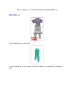
6. Add several more generic muscle shapes to fill in the leg and gluteus maximus areas.
Figure 7.53 shows the addition of six more muscles.
7. Save the scene as giraffeMuscles_v03.ma.
To see a version of the scene to this point, open the giraffeMuscles_v03.ma scene from the
chapter7\scenes directory on the DVD.
Figure 7.53
Add six more muscles
to the hind end of the
giraffe.
410
|
CHAPTER 7 rIggIng and MusCle systeMs
Editing Muscle Parameters
Muscle parameters determine how the muscle behaves as the joints are animated. If you select
the L_HindLeg_CTRL and move it around, you’ll see that the muscles stretch and squash.
Many of the settings in the Muscle Parameters section can be changed in the Channel Box or
Attribute Editor. To refine how the muscle reacts to motion, you need to have the Muscle Builder
window open.
1. Continue with the scene from the previous section, or open the giraffeMuscles_v03.ma
scene from the chapter7\scenes folder on the DVD. If it is not open already, choose
Muscle Simple Muscles Muscle Builder to open the Muscle Builder interface.
2. In the Muscle Parameters Settings section, set Draw to Muscle. If this is set to Off, you’ll
see the deformer, but changes made to the Squash and Stretch settings will not be
displayed.
The first step toward editing the muscle’s behavior is to establish its default stretch and
squash shapes based on the movement of the leg.
The giraffe’s leg is positioned in the animal’s default stance and default pose in Maya.
You can use this pose to establish the default shape of the bicep muscle. Since the giraffe
is standing, you would assume that the muscle is engaged and slightly flexed.
3. In the Spline Length Settings section, click the Set Current As Default button.
4. In the perspective view, select L_HindLeg_CTRL, and translate it to 2.0 in the Y and -3.2
in the Z. This stretches the L_bicep muscle to its extreme pose.
5. Click the Set Current as Stretch button.
6. Set the L_HindLeg_CTRL to 2.0 in the Translate Y and 4.0 in the Translate Z to push the
leg toward the chest.
7. Click the Set Current As Squash button.
8. Proceed with the rest of the leg muscles. You can move the leg forward and set all the
squash positions for those muscles that would be flexed. You do not have to do one mus-
cle at a time. Muscle Builder affects whichever muscle is selected. Figure 7.54 shows the
combination of squashed and stretched muscles.
The settings in the Stretch Volume Presets section determine how the shape muscle
deformer transitions between extreme poses. To set this properly, animate the leg so you
can adjust the settings and see the results as the leg moves.
9. Set the Time slider to 100 frames.
10. Select the L_HindLeg_CTRL, and create a short animation where the locator moves back
and forth, causing the leg to bend and straighten. Use the same values from steps 4 and 6
as your in-between frames.
11. Select the bicep muscle in the viewport.
12. Play the animation, and make sure the Muscle Builder window is still open. As the leg
moves, you may see some jiggling in the muscle; that’s part of the Jiggle settings, which
you’ll edit in the next few steps.
the Maya MusCle systeM
|
411
13. As the leg moves back and forth, click the Small, Medium, and Large buttons. Notice the
change in the muscle’s size and behavior as you switch between presets.
14. You can edit the numeric values in the START, MID, and END fields to fine-tune the
behavior. It’s usually easiest to start by loading one of the presets and then make small
changes to the values.
When you’re happy with how the muscle is shaped as it moves, you can move on to edit-
ing the Jiggle motion.
15. While the animation plays, click the Default, Light, Medium, Heavy, and OFF buttons in
the Jiggle Presets section. Observe the difference in behavior as each preset is applied.
Figure 7.54
Set the squash and
stretch of each
muscle.
412
|
CHAPTER 7 rIggIng and MusCle systeMs
16. You can fine-tune the behavior of the jiggling by editing the numeric values in the START,
MID, and END fields for Jiggle, Cycle, and Rest:
Jiggle is the intensity of jiggle.
•u
Cycle is the frequency of jiggle oscillation.•u
Rest is the time it takes for the muscle to come to a stop. •u
The Dampen settings add a damping effect as the muscle reaches extreme poses.
17. Make sure to remove any animation applied to the controls.
18. Save the scene as giraffeMuscles_v04.ma.
To see a version of the scene to this point, open the giraffeMuscles_v04.ma scene from the
chapter7\scenes directory on the DVD.
Converting the Smooth Skin to a Muscle System
Now that the muscles have been set up and are working properly, you can apply it to the giraffe
geometry so it deforms the character’s skin. Applying the deformer to the geometry involves
weighting the skin to the muscles. This is very similar in concept to smooth binding geometry
to Maya’s joints. In fact, you can actually convert the skin weights painted earlier in the chapter
to the muscle system.
1. Continue with the scene from the previous section, or open the giraffeMuscles_v04.ma
scene from the chapter7\scenes directory on the DVD.
2. Select the giraffe geometry.
3. Choose Muscle Skin Setup Convert Smooth Skin To Muscle System.
4. Maya asks whether you want to delete or disable the skin weights applied to the arm.
Choose Disable. (You can delete the weights if you want to, but it may be a good idea to
keep the weights in the scene in case they are needed later.)
5. Maya asks you to choose the axis for the capsules. Choose the x-axis to match the orienta-
tion of the capsules. Converting the skin takes a few moments (denser geometry takes
longer to process); you’ll see a dialog box that displays the progress of the calculation.
This takes the smooth skin joint weights that were painted on the geometry and con-
verts them to muscle weights. However, only the capsules are included. If you move the
L_HindLeg_CTRL, you’ll notice that the muscles do not yet deform the skin. They need
to be attached to the skin and weighted before they will work.
6. Select all the muscles and the giraffe skin.
7. Choose Muscle Muscle Objects Connect Selected Muscle Objects.
8. A dialog box asks you to set the Sticky Bind Maximum Distance value. Choose Auto-
Calculate. Each muscle is calculated.
The muscles are now connected to the skin geometry. However, it still will not affect the
geometry until the weights are painted for each muscle.
the Maya MusCle systeM
|
413
9. Switch to shaded view.
10. Select the giraffe mesh, and choose Muscle Paint Muscle Weights.
11. The geometry becomes color coded to indicate the weight strength of each muscle listed
in the Muscle Paint window. Make sure the Weight type is set to Sticky.
12. Scroll to the bottom of the list in the Muscle Paint window, and select L_glute1. The
geometry turns black, indicating there is no weight for this muscle.
13. Use the L_HindLeg_CTRL to pose the arm as you paint weight values for the glutes.
14. Set Weight to 0.1 and Operation to Add.
15. Paint over the area of the glute to start adding weights.
Low-weight values are blue.
•u
Higher-weight values are green, orange, and red. •u
You can also set the Paint Skin Weights tool to paint in Gray.
16. Paint L_glute2 as well. Figure 7.55 shows the results of painting the weights.
Figure 7.55
Paint weight val-
ues for the glute
muscles.
414
|
CHAPTER 7 rIggIng and MusCle systeMs
Keep in mind that the muscles do not have to fit perfectly under the skin. They are not
rendered with the character, so penetration is OK. The important part is how the skin
looks and reacts.
17. When you have finished painting the weights, close the window.
18. Create another animation for L_HindLeg_CTRL so you can see the muscle in action as it
deforms the skin.
19. If you need to change muscle parameters, such as the Jiggle attributes, select the muscle
and choose Muscle Simple Muscle Set Muscle Parameters. Use the settings in the
Muscle Parameters tab to adjust the muscle quality.
20. Save the scene as giraffeMuscles_v05.ma.
To see a version of the scene, open the giraffeMuscles_v05.ma scene from the chapter7\
scenes directory on the DVD.
Sliding Weights
Sliding weights are used to create the effect of skin sliding over bones and muscle. In this example,
you’ll make the skin at the top of the hind leg a little loose by painting sliding weights.
1. Continue with the scene from the previous section, or open the giraffeMuscles_v05.ma
scene from the chapter7\scenes directory on the DVD.
2. Select the giraffe mesh.
3. In the Channel Box, select the cMuscleSystem1 node under INPUTS.
4. Set Enable Sliding to On. This is an easy step to forget, but if you don’t enable sliding
weights on the character’s skin, you won’t see the sliding effects.
5. With the giraffe mesh selected, choose Muscle Paint Muscle Weights.
6. Choose the L_glute1 from the list of muscle objects.
7. Set Weights to Sliding and the operation to Add. Set Weight to 0.5.
8. Paint the muscle area.
9. Switch to L_glute2, and paint its sliding weight also.
10. Select the L_HindLeg_CTRL, and move the control handle back and forth to see the
effects of the sliding weights.
11. Save the scene as giraffeMuscles_v06.ma.
To see a version of the scene to this point, open the giraffeMuscles_v06.ma scene from the
chapter7\scenes directory on the DVD.
Creating the anatomy for an entire character takes good research and a lot of time. The
muscle system is versatile enough to only add muscles where needed. You can add them gradu-
ally to the skin and test them as you go. It is not necessary to fill the skin with muscles. To learn
more, check out the book Maya Feature Creature Creations (Charles River Media, 2002).
the BottoM lIne
|
415
The Bottom Line
Create and organize joint hierarchies A joint hierarchy is a series of joint chains. Each joint
in a chain is parented to another joint, back to the root of the chain. Each joint inherits the
motion of its parent joint. Organizing the joint chains is accomplished through naming and
labeling the joints. Proper orientation of the joints is essential for the joints to work properly.
Master it Create a joint hierarchy for a giraffe character. Orient the joints so the x-axis
points down the length of the joints.
Use Inverse Kinematics rigs A joint chain that uses Inverse Kinematics uses a goal called
an End Effector to orient the joints in the chain. A number of solvers are available in Maya.
Master it Create an Inverse Kinematic rig for a character’s leg. Use a separate control to
position the knee of the character.
Apply skin geometry Skinning geometry refers to the process in which geometry is bound
to joints so that it deforms as the joints are moved and rotated. Each vertex of the geometry
receives a certain amount of influence from the joints in the hierarchy. This can be controlled
by painting the weights of the geometry on the skin.
Master it Paint weights on the giraffe model to get smooth-looking deformations on one
side of the model. Mirror the weights to the other side.
Use Maya Muscle Maya Muscle is a series of tools designed to create more believable
deformations and movement for objects skinned to joints. Capsules are used to replace Maya
joints. Muscles are NURBS surfaces that squash, stretch, and jiggle as they deform geometry.
Master it Use Maya Muscle to create muscles for the hind leg of the giraffe. Use the
muscle system to cause skin bulging and sliding.