Mastering Autodesk Maya 2011 phần 7 docx
Bạn đang xem bản rút gọn của tài liệu. Xem và tải ngay bản đầy đủ của tài liệu tại đây (3.1 MB, 105 trang )
BuMP and norMal MaPPIng
|
601
There are two types of normal maps, object space and tangent space:
Object space maps These are used for nondeforming objects, such as walls, spaceships,
trash cans, and the like. They are calculated based on the local object space of the object. Up
in object space means toward the top of the object. If the object is rotated upside down in
world space, the top is still the top—so a robot’s head is still the top of the object in object
space even if it’s hanging upside down.
Tangent space maps These are used for deforming objects, such as characters. Tangent
space maps record the normal’s vector relative to the object’s surface. In tangent space, up
means up away from the surface of the object. Tangent space maps appear more blue and
purple since the direction in which the normal is being bent is always relative to the surface
along the tangent space z-axis. The z-axis corresponds with the blue channel (XYZ = RGB).
Object space maps, on the other hand, have more variation in color.
In practice, most artists use tangent space maps for everything. In fact, prior to Maya 2008,
tangent space maps were the only type of normal maps that Maya supported. Tangent space
maps actually work well for both deforming and nondeforming objects.
The most common way to create a normal map is to use a high-resolution, detailed version
of the model as the source of the normal map and a low-resolution version of the model as the
target for the map. The difference between the two surfaces is recorded in the colors of the map,
which is then used to alter the appearance of the low-resolution model. This is a typical process
when creating models for games where low-resolution models are required by the real-time ren-
dering engine but the audience demands realistically detailed objects.
Creating Normal Maps
In this exercise, you’ll create a normal map for the giraffe. A high-resolution version of the
model will be used as the source of the map. To create a normal map in Maya, you’ll use the
Transfer Maps tool. This tool can be used to create a number of different texture map types,
including normal maps.
1. Open the giraffeTransferMaps_v01.ma file from the chapter11\scenes folder of
the DVD.
2. In the Display Layer panel, you’ll see two layers: one labeled LORES, the other HIRES.
Turn off the LORES layer, and turn on the HIRES layer. You’ll see a higher-
resolution detailed version of the giraffe, as shown in Figure 11.35.
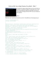
3. Turn off the HIRES layer. The geometry does not need to be visible in order to extract
maps, so if the high-resolution geometry is slowing down your computer, you can hide it.
4. Right-click the LORES layer, and choose Select Objects.
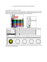
5. Under the Rendering menu set, choose Lighting/Shading Transfer Maps to open the
Transfer Maps interface (see Figure 11.36).
6. Expand the Target Meshes rollout. The loresGiraffe object is listed since it was selected
when you opened the interface. If it does not appear, select it and click the Add Selected
button. No other objects should be listed; if they are, select them in the list, and click the
Remove Selected button.
602
|
CHAPTER 11 texture MaPPIng
Figure 11.35
The high-resolution
giraffe
Figure 11.36
The Transfer
Maps interface
BuMP and norMal MaPPIng
|
603
7. Expand the Source Meshes rollout, right-click the HIRES layer, and choose Select Objects.
8. Click the Add Selected button to add it to the list.
9. Expand the Output Maps section; you’ll see icons representing all the different types of
maps that can be created.
10. Click the Normal button to add normal map to the list. If other types of maps are listed,
click the Remove Map button in the section for the map you want to remove.
11. Click the folder next to the Normal Map field, and set the location and filename for the
location of the map that will be created.
12. Choose the sourceimages directory of the current project, and name the file
giraffeHead_Nrml.
There are a number of file format options to choose from. The two best choices are Maya
IFF and EXR. Both are 32-bit formats that will ensure a detailed smooth map.
13. Choose EXR; this way you can open the map in Photoshop (CS1 and higher) for viewing
if you need to. If the file format in the name of the file is something other than .exr, it
will be automatically updated.
Open EXR Loader Plug-in
When using the EXR format in Maya, you’ll need to make sure the OpenEXRLoader plug-in
is currently loaded; otherwise, you’ll get an error when you try to connect the file to a shader.
Choose Window Settings And Plug-ins Plug-in Manager. In the list of plug-ins, make sure
OpenEXRLoader.mll is currently selected.
14. The Include Materials check box is extremely useful if you want to include a bump map
as part of the normal map. For now, deselect it since there is no bump map applied to the
high-resolution mesh material.
However, make a note of this option—you can add more detail to your normal map, such
as pores and fine wrinkles, by applying a bump texture to the shader for the high-resolu-
tion mesh object and then activating this option when using the Transfer Maps tool.
Baking Bump Maps
When baking a bump map into the normal map using the Include Materials option, the Bump Depth
setting on the shader of the source mesh will determine the intensity of the bump as it’s baked into
the normal map. If you need to change this later, you’ll need to adjust Bump Depth on the source
mesh and rebake the normal map.
15. Set Map Space to Tangent Space. You should always use tangent space maps for charac-
ters. Actually, as stated before, you can use them for any type of object.
604
|
CHAPTER 11 texture MaPPIng
16. The Use Maya Common Settings check box makes the tool use the settings specified in
the Maya Common Output. If this is deselected, sliders will appear that will allow you to
set the size of the map in this section. For now, keep this box selected.
17. In the Connect Output Maps settings, you can connect the map to a shader automatically.
Deselect the Connect Maps To Shader option for now.
Later you’ll learn how to make the connection manually. Once you understand how the
connection is made, you can use the Connect Maps To Shader option in the future to
make things more convenient.
18. In the Maya Common Output settings, enter the following:
a. Set the size of the map to 2048 in width and height.
b. Set Transfer In to Object Space, and set Sampling Quality to High.
c. Set Filter Size to 3.
d. Set Filter Type to Gaussian.
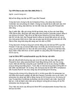
Leave Fill Texture Seams at 1 and the remaining three check boxes (Ignore Mirrored
Faces, Flip U, and Flip V) deselected. Select Bake and Close to complete the tool. The
settings are shown in Figure 11.37.
Sometimes maps do not transfer properly. Errors usually look like solid pools of color. Often
this is caused by the geometry not matching properly. To fix this, you can adjust the search enve-
lope Maya uses to extract the differences between the models. The search envelope specifies the
volume of space that Maya uses to search when creating the transfer map. Maya compares the
target geometry (the low-resolution map) with the source geometry (the high-resolution map)
and records the difference between the two as color values in the normal map. The search enve-
lope sets the limits of the distance Maya will search when creating the map. The envelope itself is
a duplicate of the target geometry that’s offset from the original. The offset distance is specified
Figure 11.37
The transfer
map’s options
BuMP and norMal MaPPIng
|
605
by the Search Envelope slider in the Target Meshes section of the Transfer Maps tool. What’s
more, you can edit the Target Mesh geometry itself to improve the results of the final map.
Use Low-Quality Settings When Testing
Normal maps can take a while to calculate, so it’s a good idea to create a few test maps at lower
quality and then raise the quality settings once you’re happy that the map is free of errors.
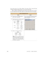
You can bake out the rest of the UV shells by selecting each group and swapping their place-
ment into the 0 to 1 texture space. Each group of shells is centered so you can snap the group to
0.5 and 0.5. Extending the grid helps keep things situated (see Figure 11.38).
Some third-party applications like Mudbox read outside the 0 to 1 texture space and can
transfer all the maps in one operation, instead of having to move the UV shell groups.
When the maps are finished, you can close the scene without saving, since no adjustments
were made. The next exercise takes you through the process of applying the normal maps.
The Transfer In option has three choices: World Space, Object Space, and UV Space. These
specify how the map will be calculated and transferred from the high-resolution version to the
low-resolution version. If the models were different sizes, then the World Space option would be
appropriate, and the models would need to be directly on top of each other. The objects used in
this tutorial are the same size and very similar except for their resolutions and level of detail, so
the Object Space option is more appropriate. The UV Space option works best for objects of fairly
similar but not exactly the same shape, such as a female human character and a male human
character.
Figure 11.38
Extend the grid to
keep the UV shell
groups organized.
606
|
CHAPTER 11 texture MaPPIng
Applying Normal Maps
Normal maps are applied to an object’s shader in the Bump channel, and they can be viewed in
the perspective window. In this section, you’ll see how the map looks when it’s applied to the
model as well as a few suggestions for fixing problems.
1. Open the giraffeUV_v07.ma file from the chapter11\scenes folder of the DVD.
2. Open the Hypershade window (Window Rendering Editors Hypershade).
3. Select the giraffe Head_Mat shader, and open its Attribute Editor.
4. Click the checkered box next to the Bump Mapping channel, and choose a file from the
Create Render Node pop-up.
5. When you add the file node, the Attribute Editor will open to the bump2D node. Set the
Use As option to Tangent Space Normals. This tells Maya the texture you’re applying is a
normal map and not a bump map. You can leave the Bump Depth at 1; it has no effect on
the strength of the normal map.
6. Switch to the file1 node, and click the folder next to the Image Name field.
7. Browse your computer’s file directory, and find the giraffeHead_Nrml.exr file; it should
be in the sourceimages directory (if you get an error when loading the image, make sure
the openEXRLoader plug-in is selected in the preferences).
Once the file is loaded, you should see a preview in the texture sample icon. The texture
should appear mostly blue and purple. If it is completely flat blue, then there was an error
during the creation process—most likely the source mesh was not selected in the Transfer
Maps options, so you’ll need to remake the map.
8. In the perspective view, choose High Quality Rendering from the Renderer menu at the
top of the panel. After a few seconds, you should see a preview of the normal map in
the perspective view. (Make sure you have Texture Shaded activated; press the 6 key to
switch to this mode.)
The normal map should make the low-resolution model look very similar to the high-
resolution model. You can see in the silhouette of the geometry that the blockiness of the
profile indicates that geometry is still low resolution, but those areas facing the camera
look highly detailed. This workflow is very popular when creating models for games. The
models end up looking much more realistic and detailed without taxing the processor of
the game console.
9. Apply the rest of the maps in the same manner. Figure 11.39 shows the giraffe with all of
its normal maps applied.
10. Inspect the model for errors in the texture.
Most likely you’ll find some errors around the lips, ears, and eyes. If large portions of the
model look wrong, you’ll need to try creating the map again. Sometimes just editing the
geometry of the search envelope can fix the errors when you regenerate the map. Other
times you may need to change the actual generation settings such as the Search Method
and Max Search Depth values in the Advanced settings.
dIsPlaCeMent MaPPIng
|
607
Normal maps are difficult but not impossible to edit in a 2D paint program such as Photoshop.
If the normal map has just a few small glitches, you can open them in Photoshop and paint each
color channel (Red, Green, and Blue) separately to clean up the maps. This can be faster than
trying to regenerate a whole new map just to fix a tiny spot.
For a completed version of the scene, open the giraffeNormalMaps_v01.ma file from the
chapter11\scenes folder on the DVD.
Displacement Mapping
Displacement maps are like bump maps in that they use a grayscale texture to add detail to a
model. However, rather than just perturb the normal of the surface, displacement maps actu-
ally alter the geometry at render time. Unlike normal and bump maps, the silhouette of the
geometry reflects the detail in the map. Displacement maps can be used with NURBS, polygon,
and subdivision surfaces and can be rendered in both mental ray and Maya Software. The best
results are usually achieved by rendering displacement maps on a polygon surface in mental ray
using mental ray’s Approximation Editor to subdivide the surface appropriately during render.
Figure 11.39
The low-resolution
model with all of
its normal maps.
608
|
CHAPTER 11 texture MaPPIng
Viewing Displacements
Displacement maps can be viewed only in a software render; they can’t be previewed in the per-
spective window.
Displacement maps are tricky to use and require some practice to master; however, the results
are often worth the time invested. Recent advances in digital sculpting programs such as
ZBrush and Mudbox have enabled modelers to bring an unprecedented amount of realism and
detail to digital characters. The detail created in these high-density meshes is often brought into
Maya in the form of displacement maps (and normal maps as well).
In addition to aiding in creating detail on creatures, displacement maps have a wide variety
of creative applications and innovations. You can use animated displacements to simulate roll-
ing waves on an ocean surface, fissures opening in the earth, or veins crawling beneath the skin.
In this section, you will apply displacement maps to the giraffe.
Converting Displacement to Polygons
If you decide you want actual geometry to be created from the displacement, you can convert
the displacement to a polygon object. This might be helpful as a stand-in object if you need to
position objects in the scene near the displaced plane or if you want to model terrain using a
procedural texture.
1. Select the plane, and choose Modify Convert Displacement To Polygons. There are
no options for this action. A second object will be created based on the original displaced
plane. Any animation of the texture will not be reflected in the converted object; it derives
its displacement from the current state of the displacing texture.
2. To increase the resolution of the converted object, increase the subdivisions in Height and
Width on the original plane. The conversion will take longer to calculate, and the result-
ing geometry will be denser.
Displacement Maps for Characters
Using displacement maps to add detail to characters is becoming increasingly common. This
allows a low-resolution version of the model to be rigged and animated and then converted into
a highly detailed mesh at render time. The end result can be quite spectacular. The render time
involved, however, makes this workflow usable only for film and television; game engines are
beginning to use displacements in real time but in a very limited capacity.
Since a displacement map is a grayscale texture, it can be painted much like a bump map.
A displacement map should be used for larger details that need to be seen in the silhouette of
the geometry, such as large folds and wrinkles in the flesh, bumps on the nose, and large veins.
Smaller details, such as pores, should be reserved for bump or normal maps that can be used
in conjunction with displacement maps. Furthermore, with characters and complex objects, the
geometry to be displaced should be fairly close in shape to the displaced version and have just
enough subdivisions to allow for the additional detail.
Maya’s Transfer Maps tool also allows for the creation of displacement maps. Generating a
workable displacement map using this tool takes a little more work than if you used a third-
party application, and it generally falls short of their precision. Through trial and error, you
dIsPlaCeMent MaPPIng
|
609
need to establish the proper displacement height. Second, the low-resolution geometry needs to
be smoothed to avoid low-resolution shading (see Figure 11.40). In addition, do not use the .exr
format to transfer the maps. The best format to use for transferring displacement maps is Maya’s
native .iff format.
The only difference between the settings in transferring normal maps and displacements
is the Maximum Value attribute. This controls the range of values the displacement is gauged
on. With the giraffe, a smaller value increases the contrast between low and high areas (see
Figure 11.41).
The best possible way to generate a displacement map for a character or creature is to use a
digital sculpting program such as ZBrush or Mudbox. Although it involves learning another
application, the results are excellent. This is becoming the workflow of choice for many major
studios. When generating maps in a third-party application, it’s always best to create 32-bit
Figure 11.40
This map was
transferred with-
out first smoothing
the surface on
the low-polygon
version.
Figure 11.41
The options used
for transferring
displacement
610
|
CHAPTER 11 texture MaPPIng
floating-point maps. This will ensure that the displacement is smooth and free of the stair-
stepping artifacts that can appear in 16-bit maps. In this exercise, mental ray’s Approximation
Editor is used to tessellate the geometry of the giraffe’s hind legs.
1. Open the giraffeDisp_v01.ma scene from the chapter11\scenes folder on the DVD.
The giraffe has all of its UV texture coordinates set for applying the displacement maps.
It is the same file used in applying normal maps except the materials have been changed
to Blinns.
2. Select the giraffe, and create an approximation node. Choose Window Rendering
Editors mental ray Approximation Editor (if mental ray does not appear in the list,
you’ll need to load the Mayatomr.mll plug-in using the Plug-in Manager).
3. In the Approximation Editor, click the Create button in the Subdivisions (Polygon
And Subd. Surfaces) section. You do not need to create a displacement approximation
node; the subdivision approximation provides enough geometry for displacement and
smoothes the surface.
4. In the Attribute Editor for the mentalRaySubdivApprox1 node, do the following:
a. Change the Approx Method set to Length/Distance/Angle.
b. Set Max Subdivisions to 3.
c. Set the Length to 0.01.
This subdivides the model so the detail created by the displacement texture is more
refined. Higher values allow more of the detail in the map to come through but also add
more triangles. The Length/Distance/Angle efficiently adds triangles where they are
needed the most. Figure 11.42 shows the settings.
5. Set the renderer to mental ray. Create a test render of the giraffe’s hind legs. It should look
nice and smooth (see Figure 11.43).
6. In the Hypershade, select giraffeHindLegs_Mat, and choose Graph Input And Output
Connections, or click its icon.
7. Open Blinn2SG in the Attribute Editor.
8. Click the checkered box next to Displacement Mat.
Figure 11.42
The settings used
for the subdivision
approximation node
dIsPlaCeMent MaPPIng
|
611
9. Choose File from the Create Render Node pop-up. An empty file node and connected
Displacement node shows up in the Hypershade.
10. Open the new file node, and name it giraffeHindLegsDisp_Text.
11. Click the folder next to the Image Name field, and use the computer’s browser to locate
the giraffeHindLegs_Disp.exr file from the sourceimages directory in the chapter11\
scenes folder on the DVD.
12. Expand the Color Balance section of the giraffeHindLegsDispFile node, and set Alpha
Gain to 0.5.
13. Turn on Alpha Is Luminance, and create a test render. The giraffe should look nice and
detailed (see Figure 11.44).
To see a finished version of the giraffe with all of its displacement maps connected, open the
giraffeDisplace_v02.ma file from the chapter11\scenes folder on the DVD.
Figure 11.43
A close-up of the
giraffe’s hind legs
rendered with a sub-
division approxima-
tion node.
612
|
CHAPTER 11 texture MaPPIng
ZBrush Displacement Maps
By default, textures created in ZBrush are upside down when imported into Maya and therefore
must be flipped. Because ZBrush interprets dark and light values in a different way than Maya,
you’ll need to make sure that the value for the texture’s Alpha Offset is -0.5 times the Alpha Gain
setting. This ensures that dark values on the displacement map push inward and lighter areas push
outward.
If your object looks bloated or distorted, double-check the Alpha Gain and Alpha Offset settings
for the file texture used for the displacement, or check to see whether Alpha Is Luminance has not
been selected.
Combined Displacement and Bump Maps
To add more detail to the giraffe, you can add a bump map to the already displaced geometry.
This is useful for fine detail too small to be created with geometry. The next exercise takes you
through the process.
1. Open the giraffeDisplace_v02.ma scene from the chapter11\scenes folder on the
DVD. All the giraffe’s displacement maps have been added.
2. Open giraffeHindLegs_Mat in the Attribute Editor.
Figure 11.44
The displacement
map adds very
realistic detail to
the rendered
character.
dIsPlaCeMent MaPPIng
|
613
3. Add a file node to the Bump Mapping channel by clicking the checkered box.
4. Set the Bump2d1 Use As option to Bump Map. Set Bump Depth to 0.02.
5. Rename the connected file node giraffeHindLegs_Bump. Use the Image Name field to
open the File Browser dialog box. Add the giraffeHindLegs_Bump.iff file from the
sourceimages directory in the chapter11\scenes folder on the DVD.
6. For testing purposes, disconnect any color maps attached to the material. Create a test
render. Figure 11.45 shows the results.
To see a completed version of the model with displacement and bumps, open the
giraffeDisplace_v03.ma scene from the chapter11\scenes folder on the DVD. Figure 11.46
shows a rendered version.
Filter
Textures have an attribute called Filter, which is found in the Special Effects rollout in the file texture
node. The Filter is a blur that Maya adds to the texture to reduce artifacts in the render. Oftentimes
this blur can reduce detail that is carefully painted into the map or can even create new artifacts. If
you find your texture maps are not rendering correctly, try setting both the Filter and Filter Offset
sliders to 0.01 as a possible solution. Setting the value to 0 may cause artifacts in some situations.
Figure 11.45
A close-up of the
giraffe’s hind legs
rendered with
displacement and
bump mapping
614
|
CHAPTER 11 texture MaPPIng
Subsurface Scattering
Subsurface scattering refers to the phenomenon of light rays bouncing around just beneath the
surface of a material before being reflected back into the environment. It’s the translucent quality
seen in objects such as jade, candle wax, and human skin (actually almost every material except
metal has some amount of subsurface scattering). Subsurface scattering adds an amazing level of
realism to CG objects and characters. It takes practice to master, but the results are worth it.
Fast, Simple Skin Shader Setup
In Maya there are several ways to create the look of subsurface scattering ranging from simple
to complex. The Translucence, Translucence Depth, and Translucence Focus sliders included on
standard Maya shaders offer the simplest way to create translucency. These sliders work fine for
an object made of a single material, such as candle wax. Likewise, the Scatter Radius slider and
related attributes in the mental ray section of Maya shaders add a quick-and-dirty subsurface
quality to simple objects. However, these options fall far short when you’re trying to create a
complex material such as human skin.
Figure 11.46
The displacement
and bump maps
are used together
to create realistic
detail in the model.
suBsurFaCe sCatterIng
|
615
Since Maya 2008, the mental ray simple subsurface scattering shaders have become much
easier to set up and use. Many of the connections that needed to be created manually in previ-
ous versions of Maya are now set up automatically when you create the shader.
There are several subsurface scattering shaders:
misss_call_shader
misss_fast_shader
misss_fast_shader_x
misss_fast_shader_x_passes
misss_fast_simple_maya
misss_fast_skin_maya
misss_physical
misss_set_normal
misss_skin_specular
With the exception of misss_physical, these shaders are all similar and use the same basic
technique for creating the effect of subsurface scattering. Some of the misss shaders are really
combined versions of others. For instance, misss_fast_skin_maya is actually a combination of
misss_fast_shader and misss_skin_specular with an extra layer of subsurface scattering. In this
chapter, you’ll focus on using the misss_fast_skin_maya shader.
Misss Shaders
The prefix misss stands for Mental Images Subsurface Scattering.
The misss_physical shader is a more complex, physically accurate shader meant to be used
with photon casting lights. For complete information on this shader, refer to mental ray for Maya,
3ds Max, and XSI by Boaz Livny (Sybex, 2008). This shader also works best for objects that
require a deep level of scattering, such as thick candles and marble.
1. Open the giraffeSSS_v01.ma scene from the chapter11\scenes folder on the DVD.
You’ll see the giraffe with mental ray’s Physical Sun and Sky shader applied.
2. Switch to the persp camera, and do a quick test render.
3. Store the image in the render view so you can compare it with the subsurface scattering
renders.
You’ll see that the character has a Blinn texture applied along with the skin, bump, and
displacement textures used in the previous section. These same file textures (along with
a few others) will be plugged into the skin shader (see Figure 11.47).
616
|
CHAPTER 11 texture MaPPIng
4. Open the Hypershade, and, on the left side, switch to the Create mental ray Nodes
section.
5. From the Materials section, create a misss_fast_skin shader. Name the shader
giraffeHeadSSS_Mat.
6. Right-click giraffeHead_Mat, and choose Select Objects With Material from the marking
menu. All the assigned faces are selected.
7. Right-click giraffeHeadSSS_Mat, and choose Assign Material To Selection from the mark-
ing menu. The parts of the giraffe assigned to the SSS shader turn a solid color in the
perspective view (depending on your graphics card, the color will vary), and that’s OK.
Maya just can’t preview some of the mental ray nodes using hardware rendering.
8. Right-click giraffeHeadSSS_Mat again, and choose Graph Network.
You’ll see that Maya has automatically created the necessary light map and texture nodes
(misss_fast_Imap_maya and mentalRayTexture1). If you select the mentalrayTexture1
node, you’ll see that the File Size Width and File Size Texture attributes are both
Figure 11.47
The giraffe ren-
dered without sub-
surface scattering
suBsurFaCe sCatterIng
|
617
highlighted in purple, indicating an expression is controlling their values. The expression
is tied to the render size automatically, so you don’t have to set these as you did in ver-
sions of Maya before 2008.
Light Maps
A light map (lmap) is a special mental ray node used to calculate the influence of light across the
surface based on the camera’s position in the scene. Light maps are used to emulate the subsurface
effect without having to perform physically based calculations. They render quickly and do a pretty
good job of faking the subsurface scattering phenomena.
9. Select giraffeHeadSSS_Mat, and open its Attribute Editor. At the top you’ll see the diffuse
layer. This layer controls the basic color of the object, much like the Color and Diffuse set-
tings in a standard shader but with a couple of differences.
Diffuse Weight controls the overall contribution, or lightness, of the combined diffuse
channels. The Overall Color channel is a multiplier for the Diffuse Color channel, so
you’ll want to put your color textures in the Diffuse Color channel and then modify it
using the Overall slider. That said, you can actually do the reverse in some cases; you
may want to experiment by putting a color texture map in the Overall Color channel.
10. In the Hypershade, switch to the Textures tab, and find the giraffeHeadDiffuse_Text
(giraffeHead_diffuse.iff) node. MMB-drag it down to the Attribute Editor on top
of the Diffuse Color channel.
The Overall Color channel is also a good place for dirt or cavity maps. In addition to add-
ing some dirt on the giraffe, it is also being used to break up the consistency of the dif-
fuse color.
11. Add a file node to the Overall color channel. Browse your computer’s file directory, and
add giraffeHead_Overall.iff.
12. Set Diffuse Weight to 0.5; you’ll probably want to adjust this more later.
13. In the Textures area of the Hypershade, find the giraffeHeadBump_Text node (this is the
texture used to create the bump texture), and MMB-drag it to the work area.
14. Expand the Bump Shader rollout in the giraffeHeadSSS_Mat, and MMB-drag the
giraffeHeadBump_Text (giraffeHead_Bump.iff) texture on top of this channel.
15. Select the bump2d node, and set Bump Depth to 0.05.
16. In the Materials tab of the Hypershade, find the giraffeHead_Disp shader. MMB-drag
this shader on top of the shading group labeled misss_fast_skin_maya3SG node, and
choose Default. These are the same displacement node, file texture, and settings created
earlier in the chapter (see Figure 11.48).
618
|
CHAPTER 11 texture MaPPIng
17. The scale of the giraffe is that 1 centimeter is equal to 1 meter. Subsurface scattering is
calculated based on meters. Therefore, you must convert the scale of the giraffe. This can
be done easily within the shader:
a. Open the Algorithm Control rollout.
b. Change Scale Conversion to 100 to multiply 1 centimeter by 100, effectively converting
it to meters.
18. Subsurface scattering does not render normally when the Physical Sun and Sky shader is
being used. There are two settings that must be changed to get it to render properly:
a. The first, Screen Composite, is on the SSS shader located in the Algorithm Control roll-
out below the Scale Conversions. Deselect Screen Composite (see Figure 11.49).
b. Next, you need to tell the shader to accept indirect lighting. This attribute is located on
the misss_fast_lmap node that was automatically generated by Maya when the SSS
shader was first created. Select Include Indirect Lighting (see Figure 11.50).
Figure 11.48
The shading
network for the
misss_fast_skin
shader has several
file textures con-
nected to it.
Figure 11.49
Deselect Screen
Composite on the
SSS shader.
Figure 11.50
Select Include Indi-
rect Lighting on
the light map.
suBsurFaCe sCatterIng
|
619
19. Create a test render to see how the giraffe looks so far.
The giraffe has a very interesting look, kind of like a plastic doll. Compare the render
with the previously stored version; notice how the color texture is not nearly as strong.
The subsurface settings need to be tuned to create a more realistic-looking skin.
20. Save your scene.
To see a version of the scene so far, open the giraffeSSS_v02.ma file from the chapter11\
scenes folder on the DVD. Figure 11.51 shows the render.
Subsurface Scattering Layers
The three channels listed under the Subsurface Scattering Layers control three different levels
of subsurface scattering. Their controls are the same except for one additional attribute slider
in the back scattering layer.
The Scatter Weight slider for each channel controls its overall contribution to the shader.
Scatter Radius controls how light scatters across the surface of the object, and Scatter Depth
(found only on Back Scatter Color in the misss_fast_skin_maya shader) controls how deeply
light penetrates into the object. The Color value for each controls the color of the subsurface
scattering; you can apply textures to all these values.
Figure 11.51
At this point, a
render of the char-
acter looks grainy
and plastic.
620
|
CHAPTER 11 texture MaPPIng
The Epidermal layer is the topmost layer, where you’ll find freckles and moles; the Subder-
mal layer is just beneath the skin, where you’ll find veins and capillaries; and the back scatter
color is the deepest layer, where bone and cartilage allow different amounts of backlighting to
show through the skin.
1. Open the giraffeSSS_v02.ma scene from the chapter11\scenes folder on the DVD.
The scene picks up where the last exercise left off.
2. If you experience a grainy quality, you can remove it by expanding the Lightmap rollout
in the SSS shader and increasing Samples to 256. Raising this value does not actually
increase render times much, but it will remove the graininess. The giraffe shaders are
doing good at the default of 64.
3. Select the giraffeHeadSSS_Mat, and connect the giraffeHead_Epidermal.iff texture
to the Epidermal Scatter Color channel. It’s common practice to use the same texture for
both the diffuse color and the uppermost layer of subsurface scattering.
4. In the Textures tab of the Hypershade, drag the subdermalScatterColor and
backScatterColor file texture nodes down into the work area.
5. Set the following values for the Subsurface Scattering Layer channels:
Epidermal Scatter Weight: 0.5
Epidermal Scatter Radius: 4.0
Subdermal Scatter Weight: 0.4
Subdermal Scatter Radius: 15.0
Back Scatter Weight: .2
Back Scatter Radius: 25.0
Back Scatter Depth: 25.0
These values are often arrived at through experimentation. The lighting, size of the scene,
and objects, along with the desired look, all affect how these values are set. In general,
when working with them, you’ll want to set all the weight values to 0 to turn them off and
then raise the weight value of each one, starting with the back scattering layer, and set their
values by tweaking and test rendering. If you arrive at settings you like, save the preset
for reuse in other scenes. You can use the Scale Conversion attribute under the Algorithm
Control rollout as a global scale adjuster for scenes and objects of different sizes.
6. Save your scene file as giraffeSSS_v03.ma.
To see a version of the scene so far, open the giraffeSSS_v03.ma file from the chapter11\
scenes folder on the DVD.
If you are dealing with a human head, it generally has cooler colors around the mouth
and eyes and in the recesses of the neck and ears (for both male and female and across races).
Warmer colors appear on the nose, cheeks, and forehead, and some yellows are seen in places
where bone is close to the surface of the skin, such as in the temples and cheekbones. These col-
ors would be represented in the subdermal and back scatter maps.
suBsurFaCe sCatterIng
|
621
Subsurface Specularity
The Subsurface Specularity attributes provide a number of ways to control how the skin of your
character reflects the lights in the scene. The giraffe is covered in fur. It still has specularity, but
it reacts very differently than bare skin. The giraffe’s specularity needs to be muted.
1. Open the giraffeSSS_v03.ma scene from the chapter11\scenes folder on the DVD. The
scene picks up where the last exercise left off.
2. In the Specularity rollout, Overall Weight adjusts how much the combined specularity
settings affect the object. Setting this to 0 turns off the specularity altogether. Set this
value to 0.3.
3. Edge Factor controls the Fresnel effect of the specular reflection. Areas of the surface that
turn away from the camera reflect more light than those that face the camera. This value
controls the width of this effect. A higher value creates a thinner edge for the highlight
on the skin. Set this value to 2.
The specularity for the skin shader has two layers to simulate the broad, overall specular-
ity of the skin as well as the shiny quality of oily or wet skin. The Primary specularity
controls the broad specular reflection and should usually have lower values than the
Secondary specularity values. The sliders themselves work the same way. Weight controls
the overall contribution; Color controls the color or texture. Edge Weight is a multiplier
for the edge of the highlight, and Shininess controls the size and intensity of the highlight
(lips will have a higher shininess than the cheeks).
4. Click the checkered box next to Primary Specular Color, and add a file node.
5. Browse your computer’s file directory, and add giraffeHead_PrimSpec.iff. Use the
following settings:
Primary Weight: 0.2
Primary Edge Weight: 0.8
Primary Shininess: 3
Secondary Weight: 0.3
Secondary Edge Weight: 0.0
Secondary Shininess: 40
The reflection settings work much like the specular values. If Reflect Environment Only
is selected, only environment maps will be used for reflection, and no reflection rays will
be generated for the object. Fur tends to break up light instead of reflecting it, so for this
scene, Reflect Weight is set to 0.0.
6. Create a test render of the scene.
To see a completed version, open the giraffeSSS_v04.ma scene from the chapter11\
scenes folder on the DVD. Compare the image (shown in Figure 11.52) with the render from
Figure 11.47. Subsurface scattering does a great deal toward adding realism to a character.
622
|
CHAPTER 11 texture MaPPIng
Baking Subsurface Scattering
Making characters look photorealistic for real-time environments is extremely difficult. While
building characters for a new game engine, we wanted to improve their overall look. Our resources
were limited. We could support only a few texture maps and could not implement any fancy shaders.
In addition to normal maps, we wanted to have some type of subsurface scattering on the charac-
ters. Since shaders were not an option, we decided to bake the rendered look of the misss_fast_skin
shader into the character’s color or diffuse maps. Here is the process:
1 . Create a misss_fast_skin shader along with all the appropriate maps, and assign it to the
character.
2 . In the Transfer Maps options window, choose Custom for the output map.
3 . Enter the exact name of the misss_fast_skin shader into the Custom Shader text field. Upon
entering the correct name, the Create button at the end of the field changes to Edit.
4 . Set the rest of the standard output options, and choose Bake and Close.
5 . The baked map looks good only from the camera’s perspective, so you can bake multiple angles
and piece them together in Photoshop to get a complete subsurface scattered texture map.
Figure 11.52
The final render
of the giraffe with
displacement,
bump, painted skin
textures, and sub-
surface scattering
the BottoM lIne
|
623
Texture Mapping NURBS Surfaces
NURBS surfaces use their own parameterization to determine texture coordinates. In other words,
you don’t need to map u- and v-coordinates using the UV layout tools. This makes NURBS easier to
work with but less flexible. NURBS take a bit more planning than polygons to texture, because you
must take into account the surface dimensions to paint a map properly. For instance, if the surface
is 10 units long by 5 units wide, you would want your texture to be twice as long as it is wide. You
can also use a projection node to place a texture onto a NURBS surface. The projection node can
then be moved in order to position the texture.
The Bottom Line
Create UV texture coordinates UV texture coordinates are a crucial element of any poly-
gon or subdivision surface model. If a model has well-organized UVs, painting texture and
displacement maps is easy and error free.
Master it Map UV texture coordinates on a giraffe’s leg; then try a complete figure.
Create bump and normal maps Bump and normal maps are two ways to add detail to a
model. Bump maps are great for fine detail, such as pores; normal maps allow you to transfer
detail from a high-resolution mesh to a low-resolution version of the same model as well as
offer superior shading and faster rendering than bump maps.
Master it Create high-resolution and low-resolution versions of the model, and try cre-
ating a normal map using the Transfer Maps tool. See whether you can bake the bump
map into the normal map.
Create a misss_fast_skin shader The misss_fast_skin shader can create extremely realistic-
looking skin. The secret is using painted texture maps for the Subsurface and Specularity
channels.
Master it Change the look of the giraffe by going from Blinn shaders to Subsurface
scattering.
Chapter 12
Rendering for Compositing
Maya offers a number of options for dividing the individual elements of a render into separate
passes. These passes can then be reassembled and processed with additional effects using com-
positing software, such as Adobe After Effects or Autodesk Composite. In this chapter, you’ll
learn how to use Maya’s render layers and mental ray’s render passes to split rendered images into
elements that can then be used in your compositing software.
For best results when working on the project files in this chapter, you should copy the
Chapter 12 project to your local drive and make sure it is the current project using the File
Project Set option. This will ensure that links to textures and Final Gathering maps remain
intact and that the scenes render correctly.
In this chapter, you will learn to:
Use render layers
•u
Use render passes•u
Perform batch renders•u
Use mental ray quality settings•u
Render Layers
Render layers are best used to isolate geometry, shaders, and lighting to create different versions
of the same animation. Render layers can be used to create a balance between efficiency and
flexibility. There is an enormous amount of creative flexibility when using render layers. This
chapter explains the more typical workflow; however, you may develop your own way of using
render layers over time.
You can create and manage render layers using the Layer Editor in Render mode (called the
Render Layer Editor). You can access the Layer Editor in the lower-right corner of the default
interface layout, just below the Channel Box.
Besides Render mode, the Layer Editor has Display and Animation modes. These three
modes are the three types of layers you can create in Maya. You change the mode by clicking
one of the tabs at the top of the Layer Editor. Figure 12.1 shows the Render Layer Editor, with a
scene that has two custom render layers and the default render layer.