Mastering Autodesk 3ds Max Design 2011 phần 2 potx
Bạn đang xem bản rút gọn của tài liệu. Xem và tải ngay bản đầy đủ của tài liệu tại đây (3.77 MB, 97 trang )
72
|
CHAPTER 2 IntroduCInG 3ds Max objeCts
2. Click the [Wireframe] label in the upper-left corner of the viewport and select Smooth +
Highlights from the context menu. Figure 2.11 clearly shows the faceting because sphere’s
Smooth parameter overrides the viewport’s Smooth + Highlights rendering mode.
3. Click the Smooth check box to turn on smoothing. In Figure 2.12, the sphere’s surface
appears smoother, although you can detect the faceting, especially around the perimeter
of the object.
4. Click and drag the Segments spinner down so that the Segments value reads 4, the lowest
possible value for a sphere. Figure 2.13 shows that the sphere becomes a pyramid shape
with the edges smoothed.
Figure 2.11
The sphere after
changing the view-
port rendering
mode
Figure 2.12
The sphere after
smoothing is
turned back on
Figure 2.13
The smoothed
sphere after the
number of seg-
ments is lowered
to four
understandInG standard PrIMItIVes
|
73
5. Click the Smooth check box again to turn off smoothing. The sphere now looks like a
pyramid with flat surfaces (see Figure 2.14).
Smoothing provides the illusion of a gradual curve, hiding the facets that are required to
construct objects. In the extreme case where a sphere is reduced to four sides, smoothing still
provides the illusion of a smooth edge, but it does not hide the sharp corners along the profile
of the sphere’s geometry.
In situations where you need to show a smooth, curved surface, the Smooth parameter is
essential. You can apply smoothing to all objects, even if they do not have a Smooth parameter
by default. You’ll learn more about applying smoothing to objects in later chapters.
Accessing Parameters
Immediately after you create an object, you can set its parameters on the Create tab of the
Command panel. However, if you create several objects and then decide you want to modify the
parameters of an object you created earlier, you’ll need to use the Modify tab of the Command
panel.
1. Click the Select Object tool, and then click a blank area of the viewport to clear your
selection set. (When you create an object, it is automatically the current selection, so you
need to click to clear the previous selection of the sphere, or you can press Ctrl+D on the
keyboard to deselect any currently selected objects.)
2. Select the sphere, which at this point looks like a pyramid with flat surfaces. Notice that
the sphere’s parameters do not appear in the Create tab of the Command panel.
3. Click the Modify tab of the Command panel. You see the parameters for the sphere, as
shown in Figure 2.15. You can now make adjustments to the sphere from the Parameters
rollout.
The Modify tab displays the parameters of any single object you select. If, however, your
selection consists of multiple objects, the individual objects’ parameters will not be available.
The Modify tab is the doorway to editing all objects in your model, as you’ll see a little later in
this chapter.
Figure 2.14
The sphere after
Smoothing is
turned off
74
|
CHAPTER 2 IntroduCInG 3ds Max objeCts
Introducing the Standard Primitive Objects
As you’ve seen, there are 10 standard primitive object types. So far, you’ve used the Box and
Sphere tools to create objects. Now let’s take a quick look at how each of the standard primi-
tives works. Although you won’t be trying every standard primitive in this chapter, the method
of creation for all of these objects is quite similar to the procedure for creating Box and Sphere
objects, so you shouldn’t have any trouble if you want to experiment with them.
The Plane primitive is perhaps the simplest of all. Click and hold to establish one corner of
the plane, and then drag to locate the other corner. Once you are satisfied with the size of the
plane, release the mouse. Figure 2.16 illustrates the procedure for creating a plane.
Figure 2.15
The sphere’s param-
eters shown in the
Modify panel
Figure 2.16
Drawing a plane
Drag to the opposite corner.
Click to place a corner.
understandInG standard PrIMItIVes
|
75
The Box, Cylinder, and Pyramid tools all work in a similar way. First, click and hold to set
one corner of the box or pyramid or, for a cylinder, the center point. Drag to locate the other cor-
ner of the box or pyramid or the radius of the cylinder. Release the mouse when you are satisfied
with the size of the base. Next, move the mouse forward or backward to establish a height. Click
when you want to fix the height. Figure 2.17 shows how to create these objects.
The Sphere and GeoSphere primitives are created in the same way. Click and hold to estab-
lish the center point, and then drag to locate the radius. When you’re satisfied with the radius,
release the mouse button. Figure 2.18 illustrates the process.
What’s the Difference Between Sphere and GeoSphere?
You may notice that both the Sphere and GeoSphere tools create the same thing—a sphere. But if
you look at the wireframe view of each of these objects, you’ll see that there’s a structural difference.
The sphere is created with horizontal and vertical segments, much like the longitude and latitude
lines on a globe. The geosphere is constructed like a geodesic dome, with triangles.
The sphere’s construction lets you convert it into a dome of varying configurations, but the geo-
sphere can only be cut to an exact hemisphere. The advantage of the geosphere is its modeling
plasticity. Because its shape is derived from a less regular construction, it can be molded more easily
into other shapes. Also, it requires fewer facets to simulate a smooth surface, which is important
when you’re creating a complex model that contains many faces.
Figure 2.17
Drawing a box,
cylinder, and
pyramid
Click to
set height.
Click and drag
from corner to
corner.
Click and drag
from center to
define radius.
Click and drag
from corner to
corner.
Click to
set height.
Click to
set height.
Figure 2.18
Drawing a sphere
and geosphere
Click and drag from center to radius.
76
|
CHAPTER 2 IntroduCInG 3ds Max objeCts
The Cone, Torus, and Tube primitives are a bit more complicated to construct, requiring a few
more steps than the other types.
Just like the cylinder, the cone starts with a click and drag to establish its center and base.
And as with the cylinder, the next step is to establish the height by positioning the mouse and
then clicking to set the height. But unlike the cylinder, the cone requires an additional step to
establish the radius of the opposite end of the cone, as shown in Figure 2.19.
The Torus object may be the most unusual of the standard primitives in its construction
method. First, click and hold to establish the center point of the torus, and then drag to locate
the radius of its tubular cross section. Release the mouse button when you’re satisfied with the
radius. Next, move the mouse forward or backward to establish the radius of the torus body.
Click the mouse when you’re satisfied with the radius. Figure 2.20 shows how to draw a torus.
Understanding the Cone Primitive
The Cone primitive is not restricted to a shape with a large base and a smaller top. The second
radius defined can just as easily be larger than the first and, with a negative Height value, it can be
below the initial radius.
Figure 2.19
Drawing a cone
Click to define the second radius.
Click and drag from center to define the first radius.
Click to set height.
Figure 2.20
Drawing a torus
Click to set
torus body radius.
Click and drag from center to the radius
of the tubular cross section.
understandInG standard PrIMItIVes
|
77
The method for creating a Tube primitive is similar to the method for creating a Cylinder
primitive but with a slight twist. Click and hold to select the center of the tube, and then drag to
establish the first radius. Release the mouse to fix the first radius. Move it again, and then click
the mouse to establish the second radius. The Radius1 and Radius2 parameters reflect the order
that the radii are determined and not which radius defines the inside or outside surfaces of the
tube. Finally, move and click the mouse to establish the height. Figure 2.21 illustrates this process.
Remember that you can make adjustments to the dimensions of the primitives after their
creation. In fact, you may find it easier to just quickly place a primitive in your model, without
giving much care to determining its size, and then adjust the dimensions of the primitive in the
Parameters rollout to fine-tune its shape.
The method for drawing a teapot (see Figure 2.22) is similar to creating a sphere. Click and
hold to select the center of the base of the teapot, and then drag to establish the overall teapot
size. There are options in the Parameters rollout to toggle the visibility of the body, handle, spout,
and lid elements. As with many of the other primitives, there is a Smooth check box and a
Segments parameter to control the density.
Figure 2.21
Drawing a tube
Click to set height.
Click to select center, and drag for first radius.
Click for second radius.
Figure 2.22
Drawing a teapot
Click to select center, and drag to
set teapot size.
78
|
CHAPTER 2 IntroduCInG 3ds Max objeCts
The History of the Teapot Primitive
The teapot is a sort of mascot of computer graphics. People have been using teapots, with their
intersecting and curved surfaces, as test and benchmark objects in renderings ever since Martin
Newell modeled the teapot form at the University of Utah in 1975 to test shading algorithms.
Modeling Standard Primitives with Modiers
You’ve seen how standard primitives have basic parameters that can be modified any time after
the creation of the primitive. Tools called modifiers can further act on a primitive to change its
form. You might think of modifiers as invisible attachments that add functions to a primitive,
in much the same way that a software plug-in adds functions to your Internet browser or other
program.
Adding a Modier
In this section, you’ll explore a few of the most commonly used modifiers offered on the Modify
tab of the Command panel. Think of this section as a general introduction to modifiers. You’ll
explore the use of other modifiers in later chapters.
You’ll start your exploration of modifiers by creating a box. You’ll use the box to try the
modifiers.
1. Expand the Application menu, and then choose New New All to start a new scene
while retaining the settings from the previous scene.
2. Click the Zoom Extents All tool to display the default view for a new file if necessary.
3. Click the Create tab in the Command panel, and then click the Box button.
4. Create a box in the Perspective viewport and then, in the Parameters rollout, set the
Length and Width to 3´ 0.0˝ and the Height to 6´ 0.0˝. Your Parameters rollout should look
like Figure 2.23.
5. If the box you created is not shaded, click the viewport shading label in the upper-left
corner of the viewport and select Smooth + Highlights. Click the label again and select
Edged Faces, or press the F4 key on your keyboard, to highlight the edges in your model.
You won’t see the effect very much on the box now, but the benefits of Edged Faces will be
apparent shortly and the effects of changes that you make to the box’s parameters will be
evident. You should have a view that looks similar to Figure 2.24. Click the Zoom Extents
button if you don’t.
Figure 2.23
Setting the box’s
parameters
ModelInG standard PrIMItIVes wIth ModIFIers
|
79
Now let’s add a modifier to change the shape of the box into a curved box:
1. Make sure the Box001 object is selected. Click the Modify tab in the Command panel.
Notice the list box, shown in Figure 2.25, with only Box listed. This is the modifier stack. You’ll
use it in the following exercises. Also notice the options in the Parameters rollout. You’ll see
the standard Length, Width, and Height options, as well as the Length Segs, Width Segs,
and Height Segs options shown here.
In the next section, you’ll see what these Segs options do.
2. Click the Modifier List drop-down arrow near the top of the Command panel. This
expands to show a scrollable list of modifiers, as shown in Figure 2.26. Notice that the list
is divided into three categories.
Figure 2.24
The box in the
viewport
Figure 2.25
Only the Box entry
shows in the Mod-
ify panel.
80
|
CHAPTER 2 IntroduCInG 3ds Max objeCts
3. Click the Bend modifier, which is under Object-Space Modifiers in the list. Notice that
Bend now appears in the modifier stack just below the Modifier List drop-down. You’ll
also see an orange outline appear, superimposed on the box. This orange box is another
gizmo, like the Move, Rotate, and Scale gizmos introduced in Chapter 1, and it shows the
general effect of the modifier. Figure 2.27 shows that the Parameters rollout changes to
show the options for the Bend modifier rather than the parametric options for the box.
4. In the Bend group of the Parameters rollout, click and drag the Angle spinner up, and
watch what happens to the box: it cants to the right, but it does not bend, as you can see in
Figure 2.28. You can see the orange Bend gizmo showing the optimum result of the modi-
fier, which is achieved only when the object is pliable enough to match it.
Figure 2.26
The Modifier List
drop-down
Figure 2.27
The Bend modi-
fier’s parameters
Figure 2.28
The canted box
shows the curved
Bend gizmo.
ModelInG standard PrIMItIVes wIth ModIFIers
|
81
5. Adjust the Angle spinner so that its value reads 60. Alternatively, you can highlight the
Angle value, and then enter 60↵.
The Bend modifier has its own set of parameters that can alter the shape of an object. This is
typical for any modifier you might use on an object. However, adding a modifier doesn’t mean
that you cannot return to the original parameters of the object to make changes there.
Accessing Modier Parameters
You’ve just applied the Bend modifier to the box, but the result may not be exactly what you
expected. The box now looks like a trapezoid. To get the box to appear curved, you need to
adjust the Segs parameters you saw earlier as part of the box’s parameters.
Currently, the object’s modifier stack contains Bend, the modifier you just added, and Box,
which is the current object type (see Figure 2.29).
1. Click Box in the modifier stack (beneath the Modifier List drop-down). Notice that the
original box parameters appear in the Parameters rollout.
2. Click the up arrow of the Height Segs spinner repeatedly and notice what happens to
the box.
Horizontal lines appear, dividing the box horizontally. The value in the Height Segs input
box shows the number of segments. Also notice that the box now appears to be curved, as
shown in Figure 2.30.
3. Set the Height Segs value to 8.
Figure 2.29
The box’s
modifier stack
Figure 2.30
The increased
Height Segs
value allows for a
smoother bend.
82
|
CHAPTER 2 IntroduCInG 3ds Max objeCts
In this exercise, you saw how you can increase the number of segments in the box, allowing
the Bend modifier to give the box a curved appearance. You also saw how the modifier stack
offers access to the box’s original parameters. The modifier stack plays a key role in your ability
to edit objects in 3ds Max, as you’ll see as you work through the examples in this book.
Now let’s try making another adjustment to the Bend modifier’s parameters:
1. Click Bend in the modifier stack. The Bend modifier’s parameters reappear.
2. Click the Direction spinner in the Parameters rollout and drag it up. Notice how the
top of the box rolls around as you change the Bend Direction parameter, while the base
remains fixed.
3. Adjust the Direction value to 180. This causes the Bend modifier to point in a direction
that is at an angle of 180 degrees from its original direction. You can see the result in
Figure 2.31.
Once again, you moved from one set of parameters to another. This time, you switched from
the box’s basic parameters to the Bend modifier’s parameters. When you adjusted the Direction
spinner in step 2, you saw how the box appeared to roll around as it changed the direction of
the bend.
You may have noticed the plus (+) sign to the left of the Bend item in the modifier stack. If
you click the plus sign, the modifier expands to show additional parameters, also called sub-
objects, available for the modifier, as shown in Figure 2.32. For the Bend modifier, Gizmo and
Center are two additional options.
As noted earlier, the Gizmo option refers to the orange shape superimposed over the box. It
lets you see how the modifier is being applied to the object. The Center option refers to the ori-
gin of the modifier object, which is usually the first point you click when you create the object.
Both the Gizmo and Center options can be edited, as you will learn in later chapters.
Figure 2.31
Changing the
Direction param-
eter alters the bend
direction.
Figure 2.32
The Bend modi-
fier’s sub-objects
ModelInG standard PrIMItIVes wIth ModIFIers
|
83
Now let’s try another modifier. The Taper modifier does just what you might guess: it tapers
an object.
1. Start by changing the view to one that will show the box from a lower angle. Click and
drag the ViewCube slightly up and to the right.
2. Click the Zoom Extents tool in the viewport navigation controls.
3. Click the Modifier List drop-down arrow and select Taper from the list. (It’s in alphabeti-
cal order under Object-Space Modifiers in the list.) Now the Parameters rollout shows a
different set of options (see Figure 2.33) specific to the Taper modifier.
Quickly Navigating the Modifier List
The modifier list shows all modifiers that can be applied to the selected objects. This list can be
long and extend beyond the display area. To quickly navigate to a modifier, press the key that cor-
responds with the first letter of the modifier’s name to highlight that modifier in the list. When
multiple modifiers exist with the same first letter (for example, Taper, Tesselate, TurboSmooth,
and so on), press the key repeatedly to continue moving down the modifier list. Press ↵ when the
desired modifier is highlighted to add it to the stack.
1. In the Parameters rollout, click and drag the Amount spinner down. The box tapers verti-
cally. You also see the orange gizmo change shape as you adjust the Amount spinner.
2. Click and drag the Curve spinner up and watch how the box bulges, as shown in
Figure 2.34.
3. Set the Curve spinner back to zero for now.
Figure 2.33
The Taper modi-
fier’s parameters
84
|
CHAPTER 2 IntroduCInG 3ds Max objeCts
Although this is an interesting form, you may have expected the box to taper along its curved
length instead of straight up. You can change the effect of the Taper modifier by changing its
position in the modifier stack, as explained in the next section.
Placing Modiers Where You Want Them
The modifier stack is a collection of modifiers, each one stacked on another one. It is important
to understand that each modifier in the stack is applied to the result of the modifier, or the
original object, located directly below it. An object that is twisted and then bent yields a much
different result than an object that is first bent and then twisted. Currently, Taper is at the top
of the modifier stack because it is the last modifier you added to the box. Below Taper is Bend,
and below Bend is the Box object itself. You can change the order of the modifiers in the stack to
obtain a slightly different effect on the box. Try the following to see how this works:
1. If the Taper entry in the modifier stack is not highlighted in gray, click to select it. If it
highlights in yellow, this is an indication that one of the sub-objects in the collapsed list is
selected—click it again to return to the modifier itself.
Take care not to click the plus sign or the lightbulb icon in the list. (Clicking the plus sign
shows additional levels of the modifier, as you saw earlier, and clicking the lightbulb
toggles the modifier off and on, as you’ll learn in the next section.)
2. Right-click and select Cut from the context menu to remove the Taper modifier from the
stack and place it temporarily into the computer’s memory.
3. Click the Box entry in the stack to select it.
4. Right-click and select Paste from the context menu. The Taper modifier is pasted just
above Box in the list, changing the order of the modifiers. Notice the change in the shape
of the box. It now tapers along the length of the bend, as shown in Figure 2.35.
This exercise demonstrated a couple of things. First, you saw how to change the order of
modifiers in the modifier stack. You also saw how a change in the order affects the way mul-
tiple modifiers work on the box. When the Taper modifier is below the Bend modifier, the box is
tapered before it is bent, giving the modified box a completely different shape. Therefore, you can
see how 3ds Max evaluates the stack from the bottom up in sequential order. Remember that the
order of the modifiers in the stack affects the way the modifiers work.
Figure 2.34
After the Amount
and Curve set-
tings have been
changed, the box
changes shape.
ModelInG standard PrIMItIVes wIth ModIFIers
|
85
What Can You Do with Primitives and Modifiers?
Some examples of objects built with the help of modifiers are the binoculars and drawer pulls
shown here:
Several objects were used for the binoculars, including cylinders and a few splines. A Taper modifier
was used to taper the large end of the binoculars, and a combination of Taper and Skew modifiers
was used in the main body. The drawer pulls are just cylinders with a Squeeze modifier applied. The
Squeeze modifier gives the cylinder a slight bulge at the top while tapering the sides down.
Dragging to Relocate Modifiers in the Stack
Instead of cutting and pasting to move a modifier in the modifier stack, you can simply click and
drag a modifier into a different location in the list. The blue bar previews where you will paste
the modifier in the stack before you release the mouse button. You can also highlight the modifier
stack entry below where you want a new modifier inserted, before selecting the modifier from the
list. New modifiers are inserted above the currently highlighted entry or at the top of the stack if
no entry is selected.
Figure 2.35
Changing the location
of the Taper modifier in
the stack changes the
appearance of the box.
86
|
CHAPTER 2 IntroduCInG 3ds Max objeCts
You also saw how the context menu lets you manipulate the modifiers. You can cut, paste,
and even delete modifiers using the context menu that appears when you right-click a modifier
label.
Using the Modier Stack Tools
You’ve seen how you can make changes to the modifier stack to fine-tune the shape of an object.
Some additional tools offer ways to manage the modifier stack. The following set of exercises
will let you see what these tools do:
1. Choose Edit Hold from the Menu Bar or select Ctrl+H. This command acts as a place
marker to which you can return, using Edit Fetch, if you want to experiment.
Saving Your Scenes Using Hold and Fetch
The Edit Hold command performs the same function as AutoCAD’s Mark option under the Undo
command. You can save your drawing in its current condition in case you want to return to this
condition later. It lets you try various what-if scenarios without the risk of losing your work up to a
certain point. Hold writes the maxhold.mx file to the AutoBackup folder specified in the Configure
User Paths dialog box, and you do not have to be in the same 3ds Max session to use the Fetch com-
mand. Be aware that there is only one maxhold.mx file. Each time Hold is used, it is overwritten
and the previous file is saved as maxhold.bak. The Fetch command is not undoable.
2. Roll up the Bend modifier by clicking the minus (-) sign to the left of its entry in the stack.
3. Click the lightbulb icon to the left of the Bend modifier.
Clicking the lightbulb icon turns off the modifier. Notice that the box changes to a shape
with a taper but without the Bend modifier.
4. Click the Bend lightbulb again to turn Bend back on.
5. Click the lightbulb next to the Taper modifier. Notice how the box reverts to the shape it
had before Taper was added.
6. Choose Edit Fetch or select Alt+Ctrl+F. You see a message box asking if it’s OK to
restore. Click Yes. Your box returns to its original state (as it was before step 1), but the
object is no longer selected.
The lightbulb icon lets you turn on or off a modifier so you can quickly view the effects of
removing a modifier from the stack without actually deleting it. A somewhat similar means is
to use the Show End Result tool. When it is turned off, the Show End Result tool simply shows
ModelInG standard PrIMItIVes wIth ModIFIers
|
87
you the shape of the object at the currently selected modifier stack level. The following example
demonstrates this:
1. Select the object in the viewport, and then select Taper in the modifier stack.
2. Click the Show End Result tool in the toolbar just below the modifier stack.
The viewport shows the box in its form before the Bend modifier is applied. Also notice
that the Show End Result icon changes into a half gray and half white bar. This helps you
remember whether the Show End Result tool is on or off.
3. Click the Select Object tool in the Main Toolbar, and then click a blank area of the model
to clear the selection. The box returns to its original form, with all of the modifiers active.
4. Click the box to select it again, and then choose Taper from the modifier stack. The box
again returns to the form it had before the Bend modifier was applied. This shows that
the Show End Result tool doesn’t actually affect the end result of the box’s modifiers, just
how the box is displayed in the viewport when it is selected.
5. Click the Show End Result tool to turn it on again. The viewport displays the box in its
final form.
Now suppose you want to simply delete a modifier from the stack. This is easy to do with the
context menu.
1. Right-click the Taper modifier in the stack and select Delete from the context menu. Now
the Taper modifier is removed from the modifier stack. The box reverts to the form it had
before you added the Taper modifier.
2. Choose Edit Fetch to restore the box with the Taper modifier intact.
Removing Modifiers from the Stack
Another way to remove a modifier from the modifier stack is to select it and then click the garbage can
icon in the toolbar below the modifier stack. This is the Remove Modifier from the Stack tool. Do not
press the Delete key on the keyboard; this deletes the selected object rather than the modifier.
88
|
CHAPTER 2 IntroduCInG 3ds Max objeCts
The Delete context-menu option is a quick way to remove a modifier. You can accomplish
the same thing by selecting the Cut option from the context menu. Another modifier stack tool
(available on the toolbar beneath the modifier stack) is Make Unique. This tool works with spe-
cial types of clones, which you’ll learn about in the “Making Clones That Share Properties” sec-
tion, coming up shortly.
How 3ds Max Sees Objects
Let’s take a break from the tutorial for a moment to understand how 3ds Max Design 2011 sees
objects. When you create and edit an object in 3ds Max, you are creating data that 3ds Max
evaluates to display your model. The order in which that data is evaluated is known as the object
data flow. 3ds Max sees objects as a stream, or flow, of data in a particular order. The order in
which this data is evaluated affects the outcome of the data; in other words, the order affects the
behavior and appearance of the object in your model.
When you rearranged the modifiers in the modifier stack, you saw an example of object data
flow. You saw that the order in which modifiers appear in the stack affects the shape of a box.
3ds Max also applies this data flow to the overall object by evaluating all modifications made to
an object in a specific order.
The first piece of data 3ds Max looks at is the master object. This is the object as you first create
it, including a set of parameters, its position, and its orientation.
The next item is the modifier or set of modifiers you apply to an object. Modifiers are evalu-
ated in their order in the modifier stack, as you’ve already seen. Of course, if there are no modi-
fiers, 3ds Max skips to the next piece of data.
The third item in the data flow consists of the transformations applied to the object. Trans-
formations refer to the movement, cloning, scaling, or rotation of an object. For example, even
though you may have moved the object before you applied modifiers, 3ds Max will evaluate the
object’s Move transformation after it evaluates its modifiers. The one exception to this occurs
when you use the XForm (transform) modifier, which places transform operations within the
bounds of the modifier stack.
3ds Max evaluates the properties of an object last. Properties include the object’s name, color,
layer assignment, display, rendering, shadow casting and receiving, motion blur, and so on. For
example, even though an object acquires a default color and name as soon as it’s created, 3ds
Max evaluates the name and color last.
To summarize object data flow, 3ds Max looks at object data in the following order:
1. Master object
2. Modifiers
3. Transforms
4. Properties
The ramifications of object data flow are not obvious at first, but keep the concept in the back
of your mind as you work with 3ds Max. It will help you understand the behavior of the pro-
gram and ultimately give you better control over your models.
MaKInG Clones that share ProPertIes
|
89
Making Clones That Share Properties
The modifier stack plays a major role in allowing you to mold objects to a desired form, but you
can go a step further and have modifiers act across several objects instead of just one. In Chapter 1,
when you learned about copying objects, you may have noticed three clone options in the Clone
Options dialog box: Copy, Instance, and Reference.
Instances and references are more than just clones of objects; they share modifiers, so the
changes you make to one clone affect all the other clones. This can be a great editing aid when
you have multiple copies of the same object, such as columns in a building, or lighting fixtures.
By making instance clones, for example, you can place the objects in your model before you’ve
finalized the particular parameters of the objects. Instances and references also reduce file size
by defining a single object or modifier that is repeated in multiple locations, rather than defining
the parameters of each identical object.
Creating an Instance Clone
The instance and reference clones are quite similar but with a subtle yet powerful difference.
You’ll start by examining the simpler of the two types of clones—the instance clone.
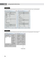
1. Open the Clone Window.max file, which you’ll find in the Chapter 2 archive at this book’s
accompanying web page, www.sybex.com/go/mastering3dsmaxdesign2011. This file
consists of a Fixed Window object with a Taper modifier applied.
If you see a File Load: Units Mismatch dialog box when you open the file, this indicates
that the file’s System Units setting is different than the current scene’s System Units set-
ting. Select the Adopt the File’s Unit Scale option and then click OK.
2. In the Perspective viewport, select the Window object, and then click the Select and
Move tool.
3. Hold the Shift key down and drag the red X-coordinate arrow to the right. Then move the
copy of the window along the X-axis toward the upper-right corner of the viewport until
it is beyond the extents of the original window.
4. Release the mouse button. The Clone Options dialog box displays, as shown in
Figure 2.36.
5. If it is not already selected, click the Instance radio button in the Object group, increase
Number of Copies to 2, and then click OK. You now have two instance clones of the origi-
nal window arranged similarly to the windows in Figure 2.37.
Pan and zoom as required to get a better view of the scene. You now have three identical
windows. The similarities of the three boxes go beyond appearances, as the following
steps demonstrate.
Figure 2.36
The Clone Options
dialog box
90
|
CHAPTER 2 IntroduCInG 3ds Max objeCts
6. With the Window object to the far right selected, click the Modify tab in the Command
panel.
7. Make sure the Taper modifier is selected in the modifier stack.
8. In the Parameters rollout, click and drag the Amount spinner down until its value reads
-0.9 and the windows have a more tapered appearance.
9. Click the FixedWindow entry in the modifier stack. In the Rails and Panels section of the
window’s Parameters rollout, change # Panels Horiz to 3 and # Panels Vert to 2.
10. Notice that all three windows change their shapes and parameters simultaneously, as
shown in Figure 2.38.
Any parameter change you make to any of the windows will be reflected in all of the instanced
clones. Furthermore, if you add additional modifiers to any of the clones, each will have the
modifier applied to the same position in its modifier stack. This is true because instance clones
share modifiers in their respective modifier stacks. This sharing of its modifiers is what distin-
guishes an instance clone from an ordinary copy. 3ds Max identifies clones by displaying their
entries in the modifier stack in a bold font.
Figure 2.37
The original
window and two
instanced clones
Figure 2.38
Altering the
parameters of one
instance changes
the parameters of
all three.
MaKInG Clones that share ProPertIes
|
91
Instances Saved Many Hours of Work
The decision was made to replace the windows in a downtown Cleveland, Ohio, office building to
improve both its appearance and energy efficiency. The company requested a 3D model to show the
city officials what the building would look like with the renovation in place. The final model had
more than 2,400 3ds Max window objects placed over 52 floors. (Window primitives are discussed in
Chapter 6, “Creating AEC Objects.”) When the model was presented the first time, it was determined
that the new window style, a sliding window with two horizontal panels, needed to look like the
existing, historical windows consisting of a single horizontal panel. Because all the windows were
instance clones, changing one window modified all the remaining windows instantly. The company
wanted to show a few windows partially opened to their 6-inch maximum, so specific windows were
selected and then the Make Unique option at the bottom of the modifier stack was used to break
the instanced connection to the other windows, thereby allowing them to open individually.
By using the Instanced option when cloning the original window, many hours of work were saved
when the window design was changed.
Creating a Reference Clone
Like an instance clone, a reference clone shares modifiers in its modifier stack, but in addi-
tion it allows you to include modifiers that are not shared. The following example shows how
this works:
1. Select the middle window.
2. With the Select and Move tool, Shift+click and drag the Move gizmo’s XY-plane to the
foreground. Relocate the window to a location similar to the one shown in Figure 2.39.
3. In the Clone Options dialog box, click the Reference radio button, and then click OK.
4. Click the clone farthest to the right (FixedWindow003) to select it.
5. Change the Taper modifier’s Amount parameter to -0.5. Now all four of the clones change
shape.
6. Click the newest clone to select it. Look carefully at the modifier stack, and you’ll see a
gray bar at the very top of the stack (see Figure 2.40). This line divides the shared modi-
fiers from potentially unshared modifiers.
Figure 2.39
The location of the
reference clone
92
|
CHAPTER 2 IntroduCInG 3ds Max objeCts
The shared modifiers of all the clones are still accessible through the reference clone.
1. With the reference clone selected, select Taper from the modifier stack.
2. In the Parameters rollout, adjust the Amount spinner down to read -0.8. All of the clones
change shape, as shown in Figure 2.41.
3. With the reference clone selected, click the blank, gray line at the top of the modifier
stack.
4. Open the Modifier List drop-down list and select Skew. (It’s in alphabetical order under
Object-Space Modifiers in the list.) The Skew modifier is now added to the top of the
modifier stack of the selected window.
5. In the Parameters rollout, set the Skew Axis to Y and then set the Amount value to
approximately -2´ 7˝ until the left edge of the window is vertical. Notice that the reference
window changes shape independently of the other windows, as shown in Figure 2.42.
Figure 2.40
The reference
clone’s modifier
stack
Figure 2.41
Changing the refer-
ence clone’s Taper
Amount spinner
affects all four
windows.
Figure 2.42
Changing the refer-
ence clone’s Skew
Amount spinner
affects only the
reference clone.
MaKInG Clones that share ProPertIes
|
93
Here, you see that the blank line in the modifier stack delineates the modifiers that are shared
between the clones from those that are specific to the selected object. Try testing this by moving
the Skew modifier below the line.
1. In the modifier stack, select Skew and then drag it below the gray line (see Figure 2.43).
Now all four windows share the Skew modifier, as shown in Figure 2.44.
2. Select the Skew modifier, right-click, and select Delete to remove it.
As you see, you can manipulate the reference clone’s modifier stack in quite a number of
ways to achieve an effect across multiple objects. Next, you’ll see another way that the stack can
be used in conjunction with a modifier to apply the transform tools to multiple objects.
3ds Max Instances Are Similar to AutoCAD Blocks
If you’re an AutoCAD user, you might think of instance and reference clones as being similar to
blocks in AutoCAD. But as you can see from these exercises, they are far more flexible in 3ds Max.
Reference clones can share some parameters and also include parameters that are independent of
other instances.
Scaling and Rotating Objects with Transform Tools
Now that you have a set of objects in your scene, let’s take a break from our look at modifiers
to examine the transform tools. In Chapter 1, you learned how you can scale and rotate a single
object using the transform tools in the Main Toolbar. You can also scale and rotate a collection of
objects by selecting the set of objects and applying the Scale or Rotate tools. When you do this,
by default 3ds Max affects all the selected objects uniformly. For example, if you rotate a collec-
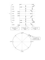
tion of objects, they all rotate about a common axis, as illustrated in the top of Figure 2.45. If you
Figure 2.43
Moving the Skew
modifier
Figure 2.44
After the Skew
modifier is relo-
cated in the modi-
fier stack, all clones
become affected.
94
|
CHAPTER 2 IntroduCInG 3ds Max objeCts
scale a collection of objects, they all change their scale, including the distance between objects in
the collection, as illustrated at the bottom of Figure 2.45.
3ds Max offers a few options that alter the way objects are affected by the transform tools. In
this section, you’ll learn how the Transform Center options give you a higher degree of control
over the transform tools.
First, try rotating one of the clones by itself:
1. Click the Select and Rotate tool on the Main Toolbar.
2. Select the window in the middle of the viewport.
3. Click and drag the red X-coordinate axis up. The window rotates independently of the
clones.
4. Click the Undo button in the Quick Access toolbar to return the window to its original
orientation.
Clones and the Transform Tools
Although this exercise involves a set of cloned objects, the transform tools in the Main Toolbar do
not consider whether the selected objects are clones of one another or a set of dissimilar objects.
Figure 2.45
Rotating objects in
a selection set (top)
and scaling objects
in a selection set
(bottom)
MaKInG Clones that share ProPertIes
|
95
Here, you see that the Rotate tool affects only the currently selected clone. You also see that
you can use the Rotate gizmo’s rings to control the orientation of the rotation.
Now, let’s take a look at how the Rotate tool affects a group of objects:
1. Click the Select Object tool, and then select all four objects. You can either click and drag
a region enclosing all of the objects or Ctrl+click each object.
2. Click the Select and Rotate tool in the Main Toolbar.
3. Click the Use Pivot Point Center tool on the Main Toolbar. If you don’t see it, click and
hold the tool just to the right of the View drop-down list in the middle of the Main
Toolbar (see Figure 2.46), and then select the Use Pivot Point Center tool from the flyout.
4. Click and drag the red X-axis ring. Now all of the cloned windows rotate in unison with
the original box, each on its own axis, as shown in Figure 2.47.
The Transform Coordinate Centers Are Transform Specific
It is important to understand that the Transform Center options are specific to the current transform
and are not global across all the transforms. For example, if the Use Pivot Point Center option is
current for all transforms and then, with the Rotate Transform active, you make the Use Selection
Center option active, it is active for only the Rotate Transform. For this reason, the transform must
be selected before the Transform Center option is changed. You can change this default parameter
by clicking Customize Preferences on the Application menu and then checking the Constant
option in the Ref. Coord. System area under the General tab of the Preference Settings dialog box.
Figure 2.46
Selecting the Use
Pivot Point Center
option
Figure 2.47
All the selected
windows rotate
in unison.
96
|
CHAPTER 2 IntroduCInG 3ds Max objeCts
Next, try the Select and Uniform Scale tool:
1. Click the Undo button to return the windows to their original orientation.
2. Click the Select and Uniform Scale tool from the flyout on the Main Toolbar.
3. Click the Use Pivot Point Center tool on the Main Toolbar, and then click and drag the
center of the Scale gizmo. Each of the windows now scales in unison with the others, each
about its own pivot point, as shown in Figure 2.48.
4. Click the Undo button to return the windows to their original size.
You’ve seen how the Use Pivot Point Center tool affects the Rotate and Scale transform tools.
Next, try the Use Transform Coordinate Center tool to see its effect on the Scale tool:
1. Click and hold the Use Pivot Point Center tool, and then select the Use Transform
Coordinate Center tool from the flyout.
Notice that the Transform gizmo now appears at the origin of the World Coordinate
System on the home grid, as shown in Figure 2.49.
Figure 2.48
The windows scale
about their own
pivot points.
Figure 2.49
With the Use
Transform Coordi-
nate Center option,
the Transform
gizmo relocates to
the origin.