Microsoft Press mcts training kit 70 - 647 enterprise administrator phần 2 pptx
Bạn đang xem bản rút gọn của tài liệu. Xem và tải ngay bản đầy đủ của tài liệu tại đây (968.18 KB, 60 trang )
32 Chapter 1 Planning Name Resolution and Internet Protocol Addressing
Exercise 2 Configure an AAAA Record
The standalone server Brisbane has an operating system that cannot register in Windows
Server 2008 DNS. Therefore, you need to create a manual AAAA record for this server. Its IPv6
address is fec0:0:0:fffe::aa. Note that you can create an AAAA record for this server even
though it does not currently exist on your network.
1. If necessary, log on to the Glasgow DC with the Kim_Akers account.
2. In Administrative Tools, open DNS Manager.
3. If a UAC dialog box appears, click Continue.
4. In DNS Manager, expand Forward Lookup Zones. Right-click contoso.internal and
choose New Host (A or AAAA).
5. Enter the server name and IPv6 address as shown in Figure 1-16. Ensure that the Create
Associated Pointer (PTR) Record check box is not selected.
Figure 1-16 Specifying a DNS host record
6. Click Add Host. Click OK to clear the DNS message box.
7. Click Done. Ensure that the new record exists in DNS Manager.
8. Close DNS Manager.
Exercise 3 Configure a Reverse Lookup IPv6 Zone
In this exercise, you will create an IPv6 reverse lookup zone for all site-local IPv6 addresses—
that is, addresses starting with fec0. You will then create a PTR record in the zone. Note that
in IPv6, reverse lookup zone addresses are entered as reverse-order 4-bit nibbles, so fec0
becomes 0.c.e.f.
Lesson 1: Planning Name Resolution 33
1. If necessary, log on to the DC with the Kim_Akers account.
2. Click Start. Right-click Command Prompt and choose Run As Administrator.
3. If a UAC dialog box appears, click Continue.
4. Enter dnscmd glasgow /ZoneAdd 0.c.e.f.ip6.arpa /DsPrimary. Figure 1-17 shows that
the zone was created successfully. Close the command console.
Figure 1-17 Creating an IPv6 reverse lookup zone
5. Open DNS Manager in Administrative Tools. If a UAC dialog box appears, click Continue.
6. Expand Forward Lookup Zones. Select contoso.internal.
7. Right-click the AAAA record for Glasgow, and then choose Properties.
8. Select the Update Associated Pointer (PTR) Record check box, as shown in Figure 1-18.
Click OK.
Figure 1-18 Creating a PTR record
9. Expand Reverse Lookup Zones and select 0.c.e.f.ip6.arpa. Ensure that the PTR record for
Glasgow exists, as shown in Figure 1-19.
34 Chapter 1 Planning Name Resolution and Internet Protocol Addressing
Figure 1-19 The PTR record for Glasgow
10. Log off from the domain controller.
Lesson Summary
■ The DNS Server role in Windows Server 2008 complies with all current standards and
can work successfully with most other DNS server implementations.
■ Windows Server 2008 DNS is dynamic and typically requires very little static configura-
tion. You can use the DNS Manager GUI or command-line interface tools such as
dnscmd, nslookup, ipconfig, and netsh to configure and manage DNS.
■ New Windows Server 2008 DNS functions include background zone loading, support
for RODCs, and the GlobalNames DNS zone. Windows Server 2008 DNS fully supports
IPv6 forward lookup and reverse lookup zones.
■ WINS resolves NetBIOS names to IP addresses. Windows Server 2008 supports WINS
to provide support for previous networks. The GlobalNames DNS zone provides single-
label name resolution for large enterprise networks that do not deploy WINS.
Lesson Review
Use the following questions to test your knowledge of the information in Lesson 1, “Planning
Name Resolution.” The questions are also available on the companion CD if you prefer to
review them in electronic form.
NOTE Answers
Answers to these questions and explanations of why each answer choice is correct or incorrect are
located in the “Answers” section at the end of the book.
Lesson 1: Planning Name Resolution 35
1. Which WINS topology uses a distributed WINS design with multiple WINS servers or
clusters deployed across the enterprise, with each server or cluster replicating with every
other server or cluster?
A. Centralized WINS topology
B. Full mesh WINS topology
C. Ring WINS topology
D. Hub and spoke WINS topology
2. Which DNS record enables you to specify refresh interval and TTL settings?
A. SOA
B. NS
C. SRV
D. CNAME
3. Which command enables a DNS server to support GlobalNames zones?
A. dnscmd /createdirectorypartition
B. dnscmd /enlistdirectorypartition
C. dnscmd /config
D. dnscmd /createbuiltindirectorypartitions
4. You want to list all the DNS records in the adatum.internal domain. You connect to the
Edinburgh.adatum.internal DNS server by using Remote Desktop and open the command
console. You type nslookup. At the nslookup> prompt, you type ls –d adatum.internal.
An error message tells you that zone data cannot be loaded to that computer. You know
all the DNS records in the domain exist on Edinburgh. Why were they not displayed?
A. You have not configured the adatum.internal forward lookup zone to allow zone
transfers.
B. You need to run the command console as an administrator to use nslookup.
C. You should have typed nslookup ls –d adatum.internal directly from the com-
mand prompt. You cannot use the ls function from the nslookup> prompt.
D. You need to log on to the DNS server interactively to use nslookup. You cannot use
it over a Remote Desktop connection.
5. A user tries to access the company internal Web site from a client computer but cannot
do so because of a network problem. You fix the network problem, but the user still can-
not reach the Web site, although she can reach other Web sites. Users on other client
computers have no problem reaching the internal Web site. How can you quickly resolve
the situation?
A. Create a static host record for your local Web server in DNS.
B. Run ipconfig /flushdns on the primary DNS server.
C. Run ipconfig /registerdns on the user’s computer.
D. Run ipconfig /flushdns on the user’s computer.
36 Chapter 1 Planning Name Resolution and Internet Protocol Addressing
Lesson 2: Planning Internet Protocol Addressing
As an experienced network professional, you are familiar with IPv4 addresses. You know that
the private IP address ranges are 10.0.0.0/8, 172.16.0.0/12, and 192.168.0.0/16 and that the
automatic IP addressing (APIPA) range is 169.254.0.0/16. You are aware that Network
Address Translation (NAT) typically enables you to use relatively few public IP addresses to
enable Internet access to many internal clients with private IP addresses. You are able to iden-
tify Class A, B, and C networks, but you are also aware that most modern network design uses
classless interdomain routing (CIDR). You know that Class D addresses (224.0.0.0/4) are
used for multicasting.
You know that DHCP can allocate IPv4 addresses, subnet masks, default gateways, DNS and
WINS servers, and many other settings and that APIPA can automatically configure IPv4
addresses for use in an isolated private network. You are aware that three DHCP infrastructure
models exist: the centralized DHCP infrastructure model, the decentralized DHCP infrastruc-
ture model, and the combined DHCP infrastructure model. You know that DHCP works with
DNS so that Host and (if appropriate) PTR records are added to DNS zones when DHCP allo-
cates IP addresses.
You might be less familiar with the IPv6 infrastructure, the advantages of IPv6, the types of
IPv6 addresses, the operation of DHCPv6 and how to set up a DHCPv6 scope, and how to
install the Windows Server 2008 DHCP server role. As IPv6 usage increases, you need to be
aware of IPv4-to-IPv6 transition strategies and Ipv4 and IPv6 interoperability, particularly the
use of Teredo addresses. This lesson looks at IPv6, DHCPv6, transition strategy, and interop-
erability. Note that the objectives of the 70-646 and 70-647 examinations are very similar for
this topic. If you studied IPv6 for the 70-646 examination, please treat this lesson as review.
After this lesson, you will be able to:
■ Identify the various types of IPv6 addresses and explain their uses.
■ Describe the advantages of IPv6 and how these are achieved.
■ Identify IPv6 addresses that can be routed on the IPv4 Internet.
■ Recommend an appropriate IPv4-to-IPv6 transition strategy.
■ Implement IPv4 and IPv6 interoperability.
■ Use IPv6 tools.
■ Configure DHCPv6 scopes.
Estimated lesson time: 55 minutes
Lesson 2: Planning Internet Protocol Addressing 37
Real World
Ian McLean
Sometimes I wonder whether NAT and CIDR did us any good in the long run.
They solved a problem. IPv4 address space exhaustion was suddenly no longer an issue.
(It will be again.) We were granted breathing space to transition to IPv6. There was and
still is a huge amount of money invested in the IPv4 intranet, and there would have been
severe problems had we suddenly found that no addresses were left. Many of us sighed
with relief.
However, the other problems haven’t gone away. Backbone routers still host huge route
tables; quality of service remains problematic when traffic is encrypted. End-to-end
security is not ensured.
Had we seen NAT and CIDR for the temporary fixes they are and implemented a con-
trolled but steady IPv6 transition, things would all have been well. Alas, it is only now,
years after the crisis loomed, that operating systems such as Windows Server 2008 and
Windows Vista that support IPv6 by default are being released. The acronym WYKIWYL
(what you know is what you like) reigned supreme. We were happy with IPv4. Why
worry about that nasty IPv6 thing? Some even grew to love NAT, seeing it as a security
enhancement. (That’s an argument I won’t go into.)
IPv6 is coming, and we can’t afford to ignore it. We need it too much. Sometimes I’m
reminded of the argument that the airplane would never catch on. It frightened the
horses.
Analyzing the IPv6 Address Structure
IPv4 and IPv6 addresses can be readily distinguished. An IPv4 address uses 32 bits, resulting
in an address space of just over 4 billion. An IPv6 address uses 128 bits, resulting in an address
space of 2
128
, or 340,282,366,920,938,463,463,374,607,431,768,211,456—a number too large
to comprehend. This represents 6.5 × 2
23
or 54,525,952 addresses for every square meter of
the earth’s surface. In practice, the IPv6 address space allows for multiple levels of subnetting
and address allocation between the Internet backbone and individual subnets within an orga-
nization. The vastly increased address space available enables users to allocate not one but sev-
eral unique IPv6 addresses to a network entity, with each address being used for a different
purpose.
IPv6 provides addresses that are equivalent to IPv4 address types and others that are unique
to IPv6. A node can have several IPv6 addresses, each of which has its own unique purpose.
This section describes the IPv6 address syntax and the various classes of IPv6 address.
38 Chapter 1 Planning Name Resolution and Internet Protocol Addressing
IPv6 Address Syntax
The IPv6 128-bit address is divided at 16-bit boundaries, and each 16-bit block is converted to
a 4-digit hexadecimal number. Colons are used as separators. This representation is called
colon-hexadecimal.
Global unicast IPv6 addresses are equivalent to IPv4 public unicast addresses. To illustrate
IPv6 address syntax, consider the following IPv6 global unicast address:
21cd:0053:0000:0000:03ad:003f:af37:8d62
IPv6 representation can be simplified by removing the leading zeros within each 16-bit block.
However, each block must have at least a single digit. With leading zero suppression, the
address representation becomes:
21cd:53:0:0:3ad:3f:af37:8d62
A contiguous sequence of 16-bit blocks set to 0 in the colon-hexadecimal format can be
compressed to ::. Thus, the previous example address could be written:
21cd:53::3ad:3f:af37:8d62
Some types of addresses contain long sequences of zeros and thus provide good examples
of when to use this notation. For example, the multicast address ff05:0:0:0:0:0:0:2 can be
compressed to ff05::2.
IPv6 Address Prefixes
The prefix is the part of the address that indicates either the bits that have fixed values or the
network identifier bits. IPv6 prefixes are expressed in the same way as CIDR IPv4 notation,
or slash notation. For example, 21cd:53::/64 is the subnet on which the address
21cd:53::23ad:3f:af37:8d62 is located. In this case, the first 64 bits of the address are the net-
work prefix. An IPv6 subnet prefix (or subnet ID) is assigned to a single link. Multiple subnet
IDs can be assigned to the same link. This technique is called multinetting.
NOTE IPv6 does not use dotted decimal notation in subnet masks
Only prefix-length notation is supported in IPv6. IPv4 dotted decimal subnet mask representation
(such as 255.255.255.0) has no direct equivalent.
IPv6 Address Types
The three types of IPv6 address are unicast, multicast, and anycast.
■ Unicast Identifies a single interface within the scope of the unicast address type.
Packets addressed to a unicast address are delivered to a single interface. RFC 2373
allows multiple interfaces to use the same address, provided that these interfaces
Lesson 2: Planning Internet Protocol Addressing 39
appear as a single interface to the IPv6 implementation on the host. This accommo-
dates load-balancing systems.
■ Multicast Identifies multiple interfaces. Packets addressed to a multicast address are
delivered to all interfaces that are identified by the address.
■ Anycast Identifies multiple interfaces. Packets addressed to an anycast address are
delivered to the nearest interface identified by the address. The nearest interface is the
closest in terms of routing distance, or number of hops. An anycast address is used for
one-to-one-of-many communication, with delivery to a single interface.
MORE INFO IPv6 addressing architecture
For more information about IPv6 address structure and architecture, see RFC 2373 at http://
www.ietf.org/rfc/rfc2373.txt.
NOTE Interfaces and nodes
IPv6 addresses identify interfaces rather than nodes. A node is identified by any unicast address
that is assigned to one of its interfaces.
IPv6 Unicast Addresses
IPv6 supports the following types of unicast address:
■ Global
■ Link-local
■ Site-local
■ Special
■ Network Service Access Point (NSAP) and Internetwork Packet Exchange (IPX) mapped
addresses
Global Unicast Addresses
Global unicast addresses are the IPv6 equivalent of IPv4 public addresses and are globally
routable and reachable on the Internet. These addresses can be aggregated to produce an effi-
cient routing infrastructure and are, therefore, sometimes known as aggregatable global uni-
cast addresses. An aggregatable global unicast address is unique across the entire Internet.
(The region over which an IP address is unique is called the scope of the address.)
The Format Prefix (FP) of a global unicast address is held in the three most significant bits,
which are always 001. The next 13 bits are allocated by the Internet Assigned Numbers
Authority (IANA) and are known as the top-level aggregator (TLA). IANA allocates TLAs to
40 Chapter 1 Planning Name Resolution and Internet Protocol Addressing
local Internet registries that, in turn, allocate individual TLAs to large ISPs. The next 8 bits of
the address are reserved for future expansion.
The next 24 bits of the address contain the next-level aggregator (NLA). This identifies a spe-
cific customer site. The NLA enables an ISP to create multiple levels of addressing hierarchy
within a network. The next 16 bits contain the site-level aggregator, which is used to organize
addressing and routing for downstream ISPs and to identify sites or subnets within a site.
The next 64 bits identify the interface within a subnet. This is the 64-bit Extended Unique
Identifier (EUI-64) address as defined by the Institute of Electrical and Electronics Engineers
(IEEE). EUI-64 addresses are either assigned directly to network adapter cards or derived from
the 48-bit Media Access Control (MAC) address of a network adapter as defined by the IEEE
802 standard. Put simply, the interface identity is provided by the network adapter hardware.
Privacy Extensions for Stateless Address Autoconfiguration in
IPv6
Concerns have been expressed that deriving an interface identity (ID) directly from
computer hardware could enable the itinerary of a laptop and, hence, that of its owner
to be tracked. This raises privacy issues, and future systems might allocate interface
IDs differently.
RFC 3041 and RFC 4941 address this problem. For more information, see http://
www.ietf.org/rfc/rfc3041.txt and />To summarize, the FP, TLA, reserved bits, and NLA identify the public topology; the site-level
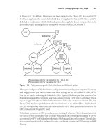
aggregator identifies the site topology; and the ID identifies the interface. Figure 1-20 illus-
trates the structure of an aggregatable global unicast address.
Figure 1-20 Global unicast address structure
MORE INFO Global unicast address format
For more information about aggregatable global unicast addresses, see RFC 2374 at http://
www.ietf.org/rfc/rfc2374.txt.
001 TLA ID Res NLA ID SLA ID Interface ID
(FP)
3 bits 13 bits 8 bits 24 bits 16 bits 64 bits
Lesson 2: Planning Internet Protocol Addressing 41
Exam Tip You need to know that an aggregatable global unicast address is the IPv6 equivalent
of an IPv4 public unicast address. You should be able to identify a global unicast address from the
value of its three most significant bits. Knowing the various components of the address helps you
understand how IPv6 addressing works, but the 70-647 examination is unlikely to test this knowl-
edge in the depth of detail provided by the RFCs.
Link-Local Addresses Link-local IPv6 addresses are equivalent to IPv4 addresses that are
autoconfigured through APIPA and use the 169.254.0.0/16 prefix. You can identify a link-local
address by an FP of 1111 1110 10, which is followed by 54 zeros. (Link-local addresses always
begin with fe8.) Nodes use link-local addresses when communicating with neighboring nodes
on the same link. The scope of a link-local address is the local link. A link-local address is
required for Neighbor Discovery (ND) and is always automatically configured, even if no other
unicast address is allocated.
Site-Local Addresses Site-local IPv6 addresses are equivalent to the IPv4 private address
space (10.0.0.0/8, 172.16.0.0/12, and 192.168.0.0/16). Private intranets that do not have a
direct, routed connection to the Internet can use site-local addresses without conflicting with
aggregatable global unicast addresses. The scope of a site-local address is the site (or organi-
zation internetwork).
Site-local addresses can be allocated by using stateful address configuration such as from a
DHCPv6 scope. A host uses stateful address configuration when it receives router advertise-
ment messages that do not include address prefixes. A host will also use a stateful address con-
figuration protocol when no routers are present on the local link.
Site-local addresses can also be configured through stateless address configuration. This is
based on router advertisement messages that include stateless address prefixes and require
that hosts do not use a stateful address configuration protocol.
Alternatively, address configuration can use a combination of stateless and stateful configura-
tion. This occurs when router advertisement messages include stateless address prefixes but
require that hosts use a stateful address configuration protocol.
MORE INFO IPv6 address autoconfiguration
For more information about how IPv6 addresses are configured, see
/technet/technetmag/issues/2007/08/CableGuy/. Although the article is titled “IPv6 Autoconfiguration
in Windows Vista,” it also covers Windows Server 2008 autoconfiguration and describes the differ-
ences between autoconfiguration on a client and on a server operating system.
Site-local addresses begin with fec0 followed by 32 zeros and then by a 16-bit subnet identifier
that you can use to create subnets within your organization. The 64-bit Interface ID field iden-
tifies a specific interface on a subnet.
42 Chapter 1 Planning Name Resolution and Internet Protocol Addressing
Figure 1-21 shows link-local and site-local addresses (for DNS servers) configured on inter-
faces on the Windows Server 2008 DC Glasgow. No global addresses exist in the configura-
tion because DCs are never exposed directly to the Internet. The IPv6 addresses on your test
computer will probably be different. Note that in this figure, the Glasgow DC has a virtual
interface to the virtual machine that hosts the Melbourne client.
Figure 1-21 IPv6 addresses on computer interfaces
Link-Local and Site-Local Addresses
You can implement IPv6 connectivity between hosts on an isolated subnet by using link-
local addresses. However, you cannot assign link-local addresses to router interfaces
(default gateways), and you cannot route from one subnet to another if only link-local
addresses are used. DNS servers cannot use only link-local addresses. If you use link-
local addresses, you need to specify their interface IDs—that is the number after the %
symbol at the end of the address, as shown previously in Figure 1-21. Link-local
addresses are not dynamically registered in Windows Server 2008 DNS.
For these reasons, site-local addresses are typically used on the subnets of a private net-
work to implement IPv6 connectivity over the network. If every device on the network
has its own global address (a stated aim of IPv6 implementation), global addresses can
route between internal subnets, to peripheral zones, and to the Internet.
Lesson 2: Planning Internet Protocol Addressing 43
Special Addresses Two special IPv6 addresses exist—the unspecified address and the loop-
back address. The unspecified address 0:0:0:0:0:0:0:0 (or ::) indicates the absence of an
address and is equivalent to the IPv4 unspecified address 0.0.0.0. It is typically used as a
source address for packets attempting to verify whether a tentative address is unique. It is
never assigned to an interface or used as a destination address. The loopback address
0:0:0:0:0:0:0:1 (or ::1) identifies a loopback interface and is equivalent to the IPv4 loopback
address 127.0.0.1.
NSAP and IPX Addresses NSAP addresses are identifying labels for network endpoints
used in Open Systems Interconnection (OSI) networking. They are used to specify a piece of
equipment connected to an Asynchronous Transfer Mode (ATM) network. IPX is no longer
widely used because modern Novell Netware networks support TCP/IP. IPv6 addresses with
an FP of 0000001 map to NSAP addresses. IPv6 addresses with an FP of 0000010 map to IPX
addresses.
Exam Tip The 70-647 examination is unlikely to include questions about NSAP or IPX mapping.
IPv6 Multicast Addresses
IPv6 multicast addresses enable an IPv6 packet to be sent to a number of hosts, all of which
have the same multicast address. They have an FP of 11111111. (They always start with ff.)
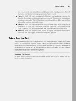
Subsequent fields specify flags, scope, and group ID, as shown in Figure 1-22.
Figure 1-22 Multicast address structure
The flags field holds the flag settings. Currently, the only flag defined is the Transient (T) flag
that uses the low-order field bit. If this flag is set to 0, the multicast address is well known—in
other words, it is permanently assigned and has been allocated by IANA. If the flag is set to 1,
the multicast address is transient.
Quick Check
■ Which type of address is fec0:0:0:eadf::1ff?
Quick Check Answer
■ Unicast site-local
1111 1111 Flags Scope Group ID
8 bits 4 bits 4 bits 112 bits
(FP)
44 Chapter 1 Planning Name Resolution and Internet Protocol Addressing
The scope field indicates the scope of the IPv6 internetwork for which the multicast traffic is
intended. Routers use the multicast scope together with information provided by multicast
routing protocols to determine whether multicast traffic can be forwarded. For example, traffic
with the multicast address ff02::2 has a link-local scope and is never forwarded beyond the
local link. Table 1-3 lists the assigned scope field values.
The group ID represents the multicast group and is unique within the scope. Permanently
assigned group IDs are independent of the scope. Transient group IDs are relevant only to a
specific scope. Multicast addresses from ff01:: through ff0f:: are reserved, well-known
addresses.
In theory, 2
112
group IDs are available. In practice, because of the way that IPv6 multicast
addresses are mapped to Ethernet multicast MAC addresses, RFC 2373, “IP Version 6
Addressing Architecture,” recommends assigning the group ID from the low-order 32 bits of
the IPv6 multicast address and setting the remaining original group ID bits to zero. In this way,
each group ID maps to a unique Ethernet multicast MAC address.
MORE INFO Assigning group IDs
For more information about assigning group IDs, see />The Solicited-Node Multicast Address The solicited-node multicast address facilitates the
querying of network nodes during address resolution. IPv6 uses the ND message to resolve a
link-local IPv6 address to a node MAC address. Rather than use the local-link scope all-nodes
multicast address (which would be processed by all nodes on the local link) as the neighbor
solicitation message destination, IPv6 uses the solicited-node multicast address. This address
comprises the prefix ff02::1:ff00:0/104 and the last 24 bits of the IPv6 address that is being
resolved.
For example, if a node has the link-local address fe80::6b:28c:16d2:c97, the corresponding
solicited-node address is ff02::1:ffd2:c97.
Table 1-3 Scope Field Values
Value Scope
0 Reserved
1 Node-local scope
2 Link-local scope
5 Site-local scope
8 Organization-local scope
e Global scope
f Reserved
Lesson 2: Planning Internet Protocol Addressing 45
The result of using the solicited-node multicast address is that address resolution uses a mech-
anism that is not processed by all network nodes. Because of the relationship between the
MAC address, the Interface ID, and the solicited-node address, the solicited-node address acts
as a pseudo-unicast address for efficient address resolution.
IPv6 Anycast Addresses
An anycast address is assigned to multiple interfaces. Packets sent to an anycast address are
forwarded by the routing infrastructure to the nearest of these interfaces. The routing infra-
structure must be aware of the interfaces that are assigned anycast addresses and their dis-
tance in terms of routing metrics. Currently, anycast addresses are used only as destination
addresses and are assigned only to routers. Anycast addresses are assigned from the unicast
address space, and the scope of an anycast address is the scope of the unicast address type
from which the anycast address is assigned.
The Subnet-Router Anycast Address The subnet-router anycast address is created from
the subnet prefix for a given interface. In a subnet-router anycast address, the bits in the subnet
prefix retain their current values, and the remaining bits are set to zero.
All router interfaces attached to a subnet are assigned the subnet-router anycast address for
that subnet. The subnet-router anycast address is used for communication with one of multi-
ple routers that are attached to a remote subnet.
Quick Check
■ A node has the link-local address fe80::aa:cdfe:aaa4:cab7. What is its corresponding
solicited-node address?
Quick Check Answer
■ ff02::1:ffa4:cab7 (the prefix ff02::1:ff00:0/104 and the last 24 bits of the link-local
address, which are a4:cab7)
Investigating the Advantages of IPv6
IPv6 was designed to overcome the limitations of IPv4. This section lists the advantages that
IPv6 has over its predecessor.
Increased Address Space
In retrospect, the 32-bit structure that IPv4 uses was not sufficient for an addressing structure.
IPv6 offers 128 bits. This gives enough addresses for every device that requires one to have a
unique public IPv6 address. In addition, the 64-bit host portion (interface ID) of an IPv6
address can be automatically generated from the network adapter hardware.
46 Chapter 1 Planning Name Resolution and Internet Protocol Addressing
Automatic Address Configuration
Typically, IPv4 is configured either manually or by using DHCP. Automatic configuration
(autoconfiguration) through APIPA is available for isolated subnets that are not routed to
other networks. IPv6 deals with the need for simpler and more automatic address configura-
tion by supporting both stateful and stateless address configuration. Stateful configuration
uses DHCPv6. If stateless address configuration is used, hosts on a link automatically config-
ure themselves with IPv6 addresses for the link and (optionally) with addresses that are
derived from prefixes advertised by local routers. You can also configure a stateless DHCPv6
configuration that does not assign addresses to hosts but can assign settings to (for example)
DNS servers whose domain names are not included in the router advertisements.
Network-Level Security
Private communication over the Internet requires encryption to protect data from being
viewed or modified in transit. Internet Protocol Security (IPsec) provides this facility, but its use
is optional in IPv4. IPv6 makes IPsec mandatory. This provides a standards-based solution for
network security needs and improves interoperability among different IPv6 implementations.
Real-Time Data Delivery
Quality of service (QoS) exists in IPv4, and bandwidth can be guaranteed for real-time traffic
(such as video and audio transmissions) over a network. However, IPv4 real-time traffic sup-
port relies on the Type of Service (ToS) field and the identification of the payload, typically using
a User Datagram Protocol (UDP) or Transmission Control Protocol (TCP) port.
The IPv4 ToS field has limited functionality, and payload identification using a TCP port and a
UDP port is not possible when an IPv4 packet payload is encrypted. Payload identification is
included in the Flow Label field of the IPv6 header, so payload encryption does not affect QoS
operation.
Quick Check
1. How many bits are in an IPv4 address?
2. How many bits are in an IPv6 address?
Quick Check Answers
1. 32
2. 128
Lesson 2: Planning Internet Protocol Addressing 47
Routing Table Size
The IPv6 global addresses used on the Internet are designed to create an efficient, hierarchical,
and summarizable routing infrastructure based on the common occurrence of multiple levels
of ISPs. On the Internet, backbone routers have greatly reduced routing tables that use route
aggregation and correspond to the routing infrastructure of top-level aggregators.
Route Aggregation
Route aggregation provides for routing of traffic for networks with smaller prefixes to
networks with larger prefixes. In other words, it permits a number of contiguous address
blocks to be combined and summarized as a larger address block. Route aggregation
reduces the number of advertised routes on large networks. When an ISP breaks its net-
work into smaller subnets to provide service to smaller providers, it needs to advertise
the route only to its main supernet for traffic to be sent to smaller providers.
Route aggregation is used when a large ISP has a contiguous range of IP addresses to
manage. IP addresses (IPv4 or IPv6) that are capable of summarization are termed
aggregatable addresses.
Header Size and Extension Headers
IPv4 and IPv6 headers are not compatible, and a host or router must use both IPv4 and IPv6
implementations to recognize and process both header formats. Therefore, the IPv6 header
was designed to be as small as was practical. Nonessential and optional fields are moved to
extension headers placed after the IPv6 header. As a result, the IPv6 header is only twice as
large as the IPv4 header, and the size of IPv6 extension headers is constrained only by the size
of the IPv6 packet.
Removal of Broadcast Traffic
IPv4 relies on Address Resolution Protocol (ARP) broadcasts to resolve IP addresses to the
MAC addresses of network interface cards (NICs). Broadcasts increase network traffic and are
inefficient because every host processes them.
The ND protocol for IPv6 uses a series of Internet Control Message Protocol for IPv6
(ICMPv6) messages that manage the interaction of nodes on the same link (neighboring
nodes). ND replaces ARP broadcasts, ICMPv4 router discovery, and ICMPv4 Redirect mes-
sages with efficient multicast and unicast ND messages.
48 Chapter 1 Planning Name Resolution and Internet Protocol Addressing
Implementing IPv4-to-IPv6 Compatibility
In addition to the various types of addresses described earlier in this lesson, IPv6 provides the
following types of compatibility addresses to aid migration from IPv4 to IPv6 and to imple-
ment transition technologies.
IPv4-Compatible Address
The IPv4-compatible address 0:0:0:0:0:0:w.x.y.z (or ::w.x.y.z) is used by dual stack nodes that
are communicating with IPv6 over an IPv4 infrastructure. The last four octets (w.x.y.z) repre-
sent the dotted decimal representation of an IPv4 address. Dual stack nodes are nodes with
both IPv4 and IPv6 protocols. When the IPv4-compatible address is used as an IPv6 destina-
tion, the IPv6 traffic is automatically encapsulated with an IPv4 header and sent to the desti-
nation using the IPv4 infrastructure.
IPv4-Mapped Address
The IPv4-mapped address 0:0:0:0:0:ffff:w.x.y.z (or ::fffff:w.x.y.z) is used to represent an IPv4-
only node to an IPv6 node and, hence, to map IPv4 devices that are not compatible with IPv6
into the IPv6 address space. The IPv4-mapped address is never used as the source or destina-
tion address of an IPv6 packet.
Teredo Address
A Teredo address consists of a 32-bit Teredo prefix. In Windows Server 2008 (and Windows
Vista), this is 2001::/32. The prefix is followed by the IPv4 (32-bit) public address of the
Teredo server that assisted in the configuration of the address. The next 16 bits are reserved for
Teredo flags. Currently, only the highest ordered flag bit is defined. This is the cone flag and is
set when the NAT device connected to the Internet is a cone NAT. A cone NAT stores the map-
ping between an internal address and port number and the public address and port number.
NOTE Windows XP and Windows Server 2003
In Windows XP and Windows Server 2003, the Teredo prefix was originally 3ffe:831f::/32. Comput-
ers running Windows XP and Windows Server 2003 use the 2001::/32 Teredo prefix when updated
with Microsoft Security Bulletin MS06-064.
The next 16 bits store an obscured version of the external UDP port that corresponds to all
Teredo traffic for the Teredo client interface. When a Teredo client sends its initial packet to a
Teredo server, NAT maps the source UDP port of the packet to a different, external UDP port.
All Teredo traffic for the host interface uses the same external, mapped UDP port. The value
representing this external port is masked or obscured by XORing it with 0xffff. Obscuring the
external port prevents NATs from translating it within the payload of packets that are being
forwarded.
Lesson 2: Planning Internet Protocol Addressing 49
The final 32 bits store an obscured version of the external IPv4 address that corresponds to all
Teredo traffic for the Teredo client interface. The external address is obscured by XORing the
external address with 0xffffffff. As with the UDP port, this prevents NAT devices from trans-
lating the external IPv4 address within the payload of packets that are being forwarded. For
example, the obscured version of the public IPv4 address 131.107.0.1 in colon-hexadecimal
format is 7c94:fffe. (131.107.0.1 equals 0x836b0001 in hexadecimal, and 0x836b0001 XOR
0xffffffff equals 0x7c94fffe.) Obscuring the external address prevents NAT devices from trans-
lating it within the payload of the packets that are being forwarded. You can perform this oper-
ation using the Windows Calculator program in Scientific View.
As a further example, Northwind Traders currently implements the following IPv4 private net-
works at its headquarters and branch offices:
■ Headquarters: 10.0.100.0 /24
■ Branch1: 10.0.0.0 /24
■ Branch2: 10.0.10.0 /24
■ Branch3: 10.0.20.0 /24
The company wants to establish IPv6 communication between Teredo clients and other
Teredo clients and between Teredo clients and IPv6-only hosts. The presence of Teredo servers
on the IPv4 Internet enables this communication to take place. A Teredo server is an IPv6/IPv4
node connected to both the IPv4 Internet and the IPv6 Internet that supports a Teredo tun-
neling interface. The Teredo addresses of the Northwind Traders networks depend on a num-
ber of factors such as the port and type of NAT server used, but they could, for example, be the
following:
■ Headquarters: 2001::ce49:7601:e866:efff:f5ff:9bfe through 2001::0a0a:64fe:e866:efff:
f5ff:9b01
■ Branch 1: 2001:: ce49:7601:e866:efff:f5ff:fffe through 2001::0a0a:0afe:e866:efff: f5ff:ff01
■ Branch 2: 2001:: ce49:7601:e866:efff:f5ff:f5fe through 2001::0a0a:14fe:e866:efff:f5ff:f501
■ Branch 3: 2001:: ce49:7601:e866:efff:f5ff:ebfe through 2001::0a0a:1efe:e866:efff:f5ff:ebfe
Note that, for example, 10.0.100.1 is the equivalent of 0a00:6401, and 0a00:6401 XORed with
ffff:ffff is f5ff:9bfe.
Exam Tip The 70-647 examination objectives specifically mention Teredo addresses, which are
supported by Microsoft. However, the examination is unlikely to ask you to generate a Teredo
address. You might, however, be asked to identify such an address and work out its included IPv4
address. Fortunately, you have access to a scientific calculator during the examination.
50 Chapter 1 Planning Name Resolution and Internet Protocol Addressing
Cone NATs
Cone NATs can be full cone, restricted cone, or port restricted cone. In a full cone NAT,
all requests from the same internal IP address and port are mapped to the same external
IP address and port, and any external host can send a packet to the internal host by
sending a packet to the mapped external address.
In a restricted cone NAT, all requests from the same internal IP address and port are
mapped to the same external IP address and port, but an external host can send a packet
to the internal host if the internal host had previously sent a packet to the external host.
In a port restricted cone NAT, the restriction includes port numbers. An external host
with a specified IP address and source port can send a packet to an internal host only if
the internal host had previously sent a packet to that IP address and port.
ISATAP Addresses
IPv6 can use an Intra-site Automatic Tunnel Addressing Protocol (ISATAP) address to commu-
nicate between two nodes over an IPv4 intranet. An ISATAP address starts with a 64-bit unicast
link-local, site-local, global, or 6to4 global prefix. The next 32 bits are the ISATAP identifier
0:5efe. The final 32 bits hold the IPv4 address in either dotted decimal or hexadecimal nota-
tion. An ISATAP address can incorporate either a public or a private IPv4 address.
For example, the ISATAP address fe80::5efe:w.x.y.z address has a link-local prefix; the
fec0::1111:0:5efe:w.x.y.z address has a site-local prefix; the 3ffe:1a05:510:1111:0:5efe:w.x.y.z
address has a global prefix; and the 2002:9d36:1:2:0:5efe:w.x.y.z address has a 6to4 global pre-
fix. In all cases, w.x.y.z represents an IPv4 address.
By default, Windows Server 2008 automatically configures the ISATAP address
fe80::5efe:w.x.y.z for each IPv4 address that is assigned to a node. This link-local ISATAP
address enables two hosts to communicate over an IPv4 network by using each other’s ISATAP
address.
You can implement IPv6-to-IPv4 configuration by using the netsh interface ipv6 6to4, netsh inter-
face ipv6 isatap, and netsh interface ipv6 add v6v4tunnel IPv6 commands. For example, to create
an IPv6-in-IPv4 tunnel between the local address 10.0.0.11 and the remote address
192.168.123.116 on an interface named Remote, you would type netsh interface ipv6 add
v6v4tunnel "Remote" 10.0.0.11 192.168.123.116.
You can also configure the appropriate compatibility addresses manually by using the netsh
interface ipv6 set address command or the Internet Protocol Version 6 (TCP/IPv6) GUI as
described in the next section of this lesson.
Lesson 2: Planning Internet Protocol Addressing 51
NOTE 6to4cfg
Windows Server 2008 does not support the 6to4cfg tool.
Planning an IPv4-to-IPv6 Transition Strategy
No specific time frame is mandated for IPv4-to-IPv6 transition. As an enterprise administrator,
one of your decisions is whether to be an early adopter and take advantage of IPv6 enhance-
ments such as addressing and stronger security or wait and take advantage of the experience
of others. Both are valid strategies.
However, you do need to find out whether your upstream ISPs support IPv6 and whether the
networking hardware in your organization (or the several organizations in your enterprise)
also supports the protocol. The most straightforward transition method, dual stack, requires
that both IPv4 and IPv6 be supported. By the same token, do not delay the decision to transi-
tion to IPv6 for too long. If you wait until the IPv4 address space is fully depleted, dual stack
will no longer be available, and you (and the users you support) will find the transition pro-
cess much more challenging.
Currently, the underlying assumption in transition planning is that an existing IPv4 infrastruc-
ture is available and that your most immediate requirement is to transport IPv6 packets over
existing IPv4 networks so that isolated IPv6 network islands do not occur. As more networks
make the transition, the requirement will change to transporting IPv4 packets over IPv6 infra-
structures to support earlier IPv4 applications and avoid isolated IPv4 islands.
Several transition strategies and technologies exist because no single strategy fits all. RFC
4213, “Basic Transition Mechanisms for Hosts and Routers,” describes the key elements of
these transition technologies, such as dual stack and configured tunneling. The RFC also
defines a number of node types based upon their protocol support, including previous sys-
tems that support only IPv4, future systems that will support only IPv6, and the dual node
that implements both IPv6 and IPv4.
MORE INFO IPv4-to-IPv6 transition
For more information about basic transition mechanisms, see and
download the white paper, “IPv6 Transition Technologies,” from />/library/bb726951.aspx.
Dual Stack Transition
Dual stack (also known as a dual IP layer) is arguably the most straightforward approach to
transition. It assumes that hosts and routers provide support for both protocols and can send
and receive both IPv4 and IPv6 packets. Thus, a dual stack node can interoperate with an IPv4
52 Chapter 1 Planning Name Resolution and Internet Protocol Addressing
device by using IPv4 packets and interoperate with an IPv6 device by using IPv6 packets. It
can also operate in one of the following three modes:
■ Only the IPv4 stack enabled
■ Only the IPv6 stack enabled
■ Both IPv4 and IPv6 stacks enabled
Because a dual stack node supports both protocols, you can configure it with both IPv4 32-bit
addresses and IPv6 128-bit addresses. It can use, for example, DHCP to acquire its IPv4
addresses and stateless autoconfiguration or DHCPv6 to acquire its IPv6 addresses. Current
IPv6 implementations are typically dual stack. An IPv6-only product would have very few com-
munication partners.
Configured Tunneling Transition
If a configured tunneling transition strategy is employed, the existing IPv4 routing infrastruc-
ture remains functional but also carries IPv6 traffic while the IPv6 routing infrastructure is
under development. A tunnel is a bidirectional, point-to-point link between two network end-
points. Data passes through a tunnel using encapsulation, in which the IPv6 packet is carried
inside an IPv4 packet. The encapsulating IPv4 header is created at the tunnel entry point and
removed at the tunnel exit point. The tunnel endpoint addresses are determined from config-
uration information that is stored at the encapsulating endpoint.
Configured tunnels are also called explicit tunnels. You can configure them as router-to-
router, host-to-router, host-to-host, or router-to-host, but they are most likely to be used in a
router-to-router configuration. The configured tunnel can be managed by a tunnel broker. A
tunnel broker is a dedicated server that manages tunnel requests coming from end users, as
described in RFC 3053, “IPv6 Tunnel Broker.”
MORE INFO Tunnel broker
For more information about tunnel brokers, see />Automatic Tunneling
RFC 2893, “Transition Mechanisms for IPv6 Hosts and Routers” (replaced by RFC 4213),
describes automatic tunneling. This enables IPv4/IPv6 nodes to communicate over an IPv4
routing infrastructure without using preconfigured tunnels. The nodes that perform auto-
matic tunneling are assigned a special type of address called an IPv4-compatible address,
which carries the 32-bit IPv4 address within a 128-bit IPv6 address format. The IPv4address
can be automatically extracted from the IPv6 address.
Lesson 2: Planning Internet Protocol Addressing 53
MORE INFO Automatic tunneling
For more information about automatic tunneling, see Be aware,
however, that the status of this document is obsolete, and RFC 4213 is the current standard.
6to4
RFC 3056, “Connection of IPv6 Domains via IPv4 Clouds,” describes the 6to4 tunneling
scheme. 6to4 tunneling enables IPv6 sites to communicate with each other via an IPv4 net-
work without using explicit tunnels and to communicate with native IPv6 domains by relay
routers. This strategy treats the IPv4 Internet as a single data link.
MORE INFO 6to4 tunneling
For more information about 6to4 tunneling, see />Teredo
RFC 4380, “Teredo: Tunneling IPv6 over UDP through Network Address Translations
(NATs),” describes Teredo, which is an enhancement to the 6to4 method and is supported by
Windows Server 2008. Teredo enables nodes that are located behind an IPv4 NAT device to
obtain IPv6 connectivity by using UDP to tunnel packets. Teredo requires the use of server and
relay elements to assist with path connectivity. Teredo address structure was discussed earlier
in this lesson.
MORE INFO Teredo
For more information about Teredo, see and http://
www.microsoft.com/technet/network/ipv6/teredo.mspx.
Intra-Site Automatic Tunneling Addressing Protocol
RFC 4214, “Intra-Site Automatic Tunnel Addressing Protocol (ISATAP),” defines ISATAP,
which connects IPv6 hosts and routers over an IPv4 network, using a process that views the
IPv4 network as a link layer for IPv6, and other nodes on the network as potential IPv6 hosts
or routers. This creates a host-to-host, host-to-router, or router-to-host automatic tunnel.
MORE INFO ISATAP
For more information about ISATAP, see and download the
“Manageable Transition to IPv6 Using ISATAP” white paper from />/details.aspx?FamilyId=B8F50E07-17BF-4B5C-A1F9-5A09E2AF698B&displaylang=en.
54 Chapter 1 Planning Name Resolution and Internet Protocol Addressing
Using IPv6 Tools
Windows Server 2008 provides tools with which you can configure IPv6 interfaces and
check IPv6 connectivity and routing. Tools also exist that implement and check IPv4 to IPv6
compatibility.
In Windows Server 2008, the standard command-line tools such as ping, ipconfig, pathping,
tracert, netstat, and route have full IPv6 functionality. For example, Figure 1-23 shows the ping
command used to check connectivity with a link-local IPv6 address on a test network. The
IPv6 addresses on your test network will be different. Note that if you were pinging from one
host to another, you would also need to include the interface ID, for example, ping
fe80::fd64:b38b:cac6:cdd4%15. Interface IDs are discussed later in this lesson.
Figure 1-23 Pinging an IPv6 address
NOTE Ping6
The ping6 command-line tool is not supported in Windows Server 2008.
Tools specific to IPv6 are provided in the netsh (network shell) command structure. For exam-
ple, the netsh interface ipv6 show neighbors command shows the IPv6 interfaces of all hosts on
the local subnet. You use this command in the practice session later in this lesson, after you
have configured IPv6 connectivity on a subnet.
Verifying IPv6 Configuration and Connectivity
If you are troubleshooting connectivity problems or merely want to check your configuration,
arguably the most useful tool—and certainly one of the most used—is ipconfig. The ipconfig /all
tool displays both IPv4 and IPv6 configuration. The output from this tool was shown in Figure
1-21 earlier in this lesson.
If you want to display the configuration of only the IPv6 interfaces on the local computer, you
can use the netsh interface ipv6 show address command. Figure 1-24 shows the output of this
Lesson 2: Planning Internet Protocol Addressing 55
command run on the Glasgow computer. Note the % character followed by a number after
each IPv6 address. This is the interface ID, which identifies the interface that is configured
with the IPv6 address.
Figure 1-24 Displaying IPv6 addresses and interface IDs
If you are administering an enterprise network with a number of sites, you also need to know
site IDs. You can obtain a site ID by using the netsh interface ipv6 show address level=verbose
command. Part of the output from this command is shown in Figure 1-25.
Figure 1-25 Displaying IPv6 addresses and site IDs
Configuring IPv6 Interfaces
Typically, most IPv6 addresses are configured through autoconfiguration or DHCPv6. How-
ever, if you need to configure an IPv6 address manually, you can use the netsh interface ipv6 set
address command, as in this example: netsh interface ipv6 set address “local area connection 2”
fec0:0:0:fffe::2 where “local area connection 2” is the name of the network connection that you
wish to configure. You need to run the command console (also known as the command
prompt) as an administrator to use this command. In Windows Server 2008 (and in Windows
Vista), you can also manually configure IPv6 addresses from the properties of the TCP/IPv6
GUI. Figure 1-26 shows this configuration.
56 Chapter 1 Planning Name Resolution and Internet Protocol Addressing
Figure 1-26 Configuring an IPv6 address through a GUI
The advantage of using the TCP/IPv6 GUI is that you can specify the IPv6 addresses of one or
more DNS servers in addition to specifying the interface address. If, however, you choose to
use command-line interface commands, the command to add the IPv6 addresses of DNS serv-
ers is netsh interface ipv6 add dnsserver, as in this example: netsh interface ipv6 add dnsserver
"local area connection 2” fec0:0:0:fffe::1. To change the properties of IPv6 interfaces (but not
their configuration), use the netsh interface ipv6 set interface command, as in this example: netsh
interface ipv6 set interface “local area connection 2” forwarding=enabled. You need to run the com-
mand console (command prompt) as an administrator to use the netsh interface ipv6 add and
netsh interface ipv6 set commands.
Quick Check
■ Which netsh command lists site IDs?
Quick Check Answer
■ netsh interface ipv6 show address level=verbose
Verifying IPv6 Connectivity
To verify connectivity on a local network, your first step should be to flush the neighbor cache,
which stores recently resolved link-layer addresses and might give a false result if you are
checking changes that involve address resolution. You can check the contents of the neighbor
cache by using the netsh interface ipv6 show neighbors command. The netsh interface ipv6 delete