Multiple User InterfacesCross-Platform Applications and Context-Aware Interfaces phần 4 doc
Bạn đang xem bản rút gọn của tài liệu. Xem và tải ngay bản đầy đủ của tài liệu tại đây (768.28 KB, 42 trang )
100 MIR FAROOQ ALI, MANUEL A. P
´
EREZ-QUI
˜
NONES, AND MARC ABRAMS
they have a high threshold, a low ceiling, and unpredictability. A high threshold means
that the toolkit often requires the developer to learn specialized languages in order to use
it. A low ceiling indicates that the toolkit only works for a small class of UI applications
(e.g. a Web-based UI tool that will not work with other interface styles). Developers
quickly run into the toolkit’s limitations. Finally, a toolkit’s unpredictability is due in large
part to its approach. Most unpredictable tools apply sophisticated artificial intelligence
algorithms to generate their interface. As a result, it is difficult for the developer to know
what to modify in the high-level model in order to produce a desired change in the
UI. UIML, while similar in nature to some of the other model-based tools, has a few
new design twists that make it interesting from a UI research and development point
of view.
First, the language is designed for multiple platforms and families of devices. This is
done without attempting to define a lowest common denominator of device functionality.
Instead, UIML uses a generic vocabulary and other techniques to produce interfaces for
the different platforms. The advantage of this approach is that while developers will still
need to learn a new language (namely, UIML), this language is all they will need to know
to develop UIs for multiple platforms. This helps lower the threshold of using UIML.
Secondly, UIML provides mapping to a platform’s toolkit. Thus, UIML in and of itself
does not restrict the types of applications that can be developed for different platforms.
Therefore, UIML has a high ceiling.
Finally, predictability is not an issue because UIML does not use sophisticated arti-
ficial intelligence algorithms to generate UIs. Instead, it relies on a set of simple trans-
formations (taking advantage of XML’s capabilities) that produce the resulting inter-
face. From the developer’s point of view, it is clear which part of the UIML spec-
ification generates a specific part of the UI. Furthermore, the tools we are building
attempt to make this relationship between different levels of specification more clear
to the developer.
6.4. UIML
UIML [Abrams and Phanouriou 1999; Phanouriou 2000] is a declarative XML-based lan-
guage that can be used to define user interfaces. One of the original design goals of UIML
was to ‘reduce the time to develop user interfaces for multiple device families’ [Abrams
et al. 1999]. A related design rationale behind UIML was to ‘allow a family of interfaces
to be created in which the common features are factored out’ [Abrams and Phanouriou
1999]. This indicates that the capability to create multi-platform UIs was inherent in the
design of UIML.
Although UIML allows a multi-platform description of UIs, there is limited common-
ality between the platform-specific descriptions when platform-specific vocabularies are
used. This means that the UI designer will have to create separate UIs for each platform
using its own vocabulary. Recall that a vocabulary is defined to be a set of UI elements
with associated properties and behaviour. Limited commonality is not a shortcoming of
UIML itself, but a result of the inherent differences between platforms with varying
form factors.
BUILDING MULTI-PLATFORM USER INTERFACES WITH UIML 101
One of the primary design goals of UIML is to provide a single, canonical format for
describing UIs that map to multiple devices. Phanouriou [2000] lists some of the criteria
used in designing UIML:
1. UIML should map the canonical UI description to a particular device/platform.
2. UIML should separately describe the content, structure, behaviour and style of a UI.
3. UIML should describe the UI’s behaviour in a device-independent fashion.
4. UIML should give as much power to a UI implementer as a native toolkit.
6.4.1. LANGUAGE OVERVIEW
Since UIML is XML-based, the different components of a UI are represented through
a set of tags. The language itself does not contain any platform-specific or metaphor-
dependent tags. For example, there is no tag like
<window> that is directly linked to the
desktop metaphor of interaction. Platform-specific renderers have to be built in order to
render the interface defined in UIML for that particular platform. Associated with each
platform-specific renderer is a vocabulary of the language widget-set or tags that are used
to define the interface on the target platform.
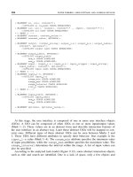
Below, we see a UIML document skeleton:
<?xml version="1.0"?>
<!DOCTYPE uiml PUBLIC "-//UIT//DTD
UIML 2.0 Draft//EN" UIML2_Of.dtd">
<uiml>
<head> </head>
<interface> </interface>
<peers> </peers>
<template> </template>
</uiml>
Figure 6.2. Skeleton of a UIML document.
At its highest level, a UIML document is comprised of four components: <head>,
<interface>, <peers> and <template>.The<interface> and the <peers>
are the only components that are relevant to this discussion; information on the others
can be found elsewhere [Phanouriou 2000].
6.4.2. THE
<INTERFACE> COMPONENT
This is the heart of the UIML document in that it represents the actual UI. All of the UIML
elements that describe the UI are present within this tag. Its four main components are:
<structure>: The physical organization of the interface, including the relation-
ships between the various UI elements within the interface, is represented with this tag.
Each
<structure> is comprised of <part> tags. Each <part> represents an actual
platform-specific UI element and is associated with a single class (i.e. category) of UI
elements. One may nest
<part> tags to represent a hierarchical relationship. There might
102 MIR FAROOQ ALI, MANUEL A. P
´
EREZ-QUI
˜
NONES, AND MARC ABRAMS
be more than one <structure> root in a UIML document, each representing different
organizations of the same UI. This allows one to support multiple families or platforms.
<style>:The<style> tag contains a list of properties and values used to render the
UI. The properties are usually associated with individual parts within the UIML document
through the part-names. Properties can also be associated with particular classes of parts.
Typical properties associated with parts for Graphical User Interfaces (GUIs) could be
the background colour, foreground colour, font, etc. It is also possible to have multiple
styles within a single UIML document associated with multiple structures or even the
same structure. This facilitates the use of different styles for different contexts.
<content>: This tag holds the subject matter associated with the various parts of the
UI. A clean separation of the content from the structure is useful when different content
is needed under different contexts. This feature of UIML is very helpful when creating
UIs that might be displayed in multiple languages. An example of this is a UI in French
and English, for which different content is needed in each language.
<behavior>: Enumerating a set of conditions and associated actions within rules
specifies the behaviour of a UI. UIML permits two types of conditions: the first condition is
true when an event occurs, while the second condition is true when an event occurs and an
associated datum is equal to a particular value. There are four kinds of actions that occur:
the first action assigns a value to a property, the second action calls an external function
or method, the third action launches an event and the fourth action restructures the UI.
6.4.3. THE
<PEERS> COMPONENT
UIML provides a <peers> element to allow the mapping of class names and events
(within a UIML document) to external entities. There are two child elements within a
<peers> element:
The
<presentation> element contains mappings of part and event classes, property
names, and event names to a UI toolkit. This mapping defines a vocabulary to be used with
a UIML document, such as a vocabulary of classes and names for VoiceXML or WML.
The
<logic> element provides the glue between UIML and other code. It describes
the calling conventions for methods that are invoked by the UIML code. An extremely
detailed discussion of the language design issues can be found in Phanouriou’s disserta-
tion [Phanouriou 2000].
6.4.4. A SAMPLE UI
To better understand the features of the language, consider the sample UI displayed in
Figure 6.3. A UIML renderer for Java produced this UI. The UIML code corresponding
to this interface is presented in Figure 6.4. The UI itself is pretty simple. As indicated in
Figure 6.3, the UI displays the string ‘Hello World!’ Clicking on the button changes the
string’s content and colour.
An important point to be observed here is that the UIML code in Figure 6.4 is platform-
specific for the Java AWT/Swing platform. Hence, we observe the use of Java Swing-
specific UIML part-names like JFrame, JButton and JLabel in the UIML code. The UI
BUILDING MULTI-PLATFORM USER INTERFACES WITH UIML 103
Figure 6.3. Sample interface.
is comprised of the label for the string and the button, both of which are enclosed in a
container. This relationship is indicated in the structure part of the UIML code. The other
presentation and layout characteristics of the parts are indicated in UIML through various
properties. All these properties can be grouped together in the style section. Note that
each property for a part is indicated through a name. What actually happens when a user
interacts with the UI is indicated in the
<behavior> section of the UIML document.
In this example, two actions are triggered when the user clicks the button: ‘Hello World’
changes to ‘I’m red now’, and the text’s colour changes to red. As indicated in Figure 6.4,
this is presented in UIML in the form of a rule that in turn is composed of two parts: a
condition and an action.
Currently, there are platform-specific renderers available for UIML for a number of
different platforms. These include Java, HTML, WML, and VoiceXML. Each of these
renderers has a platform-specific vocabulary associated with it to describe its UI elements,
behaviour and layout. The UI developer uses the platform-specific vocabulary to create
a UIML document that is rendered for the target platform. The example presented in
Figure 6.4 is an example of UIML used with a Java Swing vocabulary. The renderers are
available from />There is a great deal of difference between the vocabularies associated with each
platform. Consequently, a UI developer will have to learn each vocabulary in order to build
UIs that will work across multiple platforms. Using UIML as the underlying language for
cross-platform UIs reduces the amount of effort required in comparison with the effort
that would be required if the UIs had to be built independently using each platform’s
native language and toolkit.
Unfortunately, UIML alone cannot solve the problem of creating multi-platform UIs.
The differences between platforms are too significant to create one UIML file for one
particular platform and expect it to be rendered on a different platform with a simple
change in the vocabulary. In the past, when building UIs for platforms belonging to
different families, we have had to redesign the entire UI due to the differences between
the platform vocabularies and layouts. In order to solve this problem, we have found
that more abstract representations of the UI are necessary, based on our experience with
creating a variety of UIs for different platforms. The abstractions in our approach include
using a task model for all families and a generic vocabulary for one particular family.
These approaches are discussed in detail in the following sections.
104 MIR FAROOQ ALI, MANUEL A. P
´
EREZ-QUI
˜
NONES, AND MARC ABRAMS
<?xml version="1.0" encoding="ISO-8859-1" ?>
<!DOCTYPE uiml PUBLIC "-//Harmonia//DTD UIML 2.0 Draft//EN"
"UIML2_0g.dtd">
<uiml>
<head>
<meta name="Purpose" content="Hello World UIML example"/>
</head>
<interface>
<structure>
<part id="HWF" class="JFrame">
<part id="HWL" class="JLabel"/>
<part id="HWB" class="JButton"/>
</part>
</structure>
<style>
<property part-name="HWF" name="title">Hello World Window
</property>
<property part-name="HWF" name="layout">java.awt.FlowLayout
</property>
<property part-name="HWF" name="resizable">true</property>
<property part-name="HWF" name="background">CCFFFF</property>
<property part-name="HWF" name="foreground">black</property>
<property part-name="HWF" name="size">200,100</property>
<property part-name="HWF" name="location">100,100</property>
<property part-name="HWL" name="font">ProportionalSpaced-Bold-16
</property>
<property part-name="HWL" name="text">Hello World!</property>
<property part-name="HWB" name="text">Click me!</property>
</style>
<behavior>
<rule>
<condition>
<event class="actionPerformed" part-name="HWB"/>
</condition>
<action>
<property part-name="HWL" name="foreground">FF0000</property>
<property part-name="HWL" name="text">I'm red now!</property>
</action>
</rule>
</behavior>
</interface>
<peers>
<presentation base="Java_1.3_Harmonia_1.0"
source="Java_1.3_Harmonia_1.0.uiml#vocab"/>
</peers>
</uiml>
Figure 6.4. UIML code for sample UI in Figure 6.3.
6.5. A FRAMEWORK FOR MULTI-PLATFORM
UI DEVELOPMENT
The concept of building multi-platform UIs is relatively new. To envision the development
process, we consider an existing, traditional approach from the Usability Engineering (UE)
literature. One such approach, [Hix and Hartson 1993], identifies three different phases in
BUILDING MULTI-PLATFORM USER INTERFACES WITH UIML 105
the UI development process: interaction design, interaction software design and interaction
software implementation.
Interaction design is the phase of the usability engineering cycle in which the ‘look and
feel’ and behaviour of a UI is designed in response to what a user hears, sees or does. In
current UE practices, this phase is highly platform-specific. Once the interaction design is
complete, the interaction software design is created. This involves making decisions about
UI toolkit(s), widgets, positioning of widgets, colours, etc. Once the interaction software
design is finished, the software is implemented.
The above paragraph describes the traditional view of interaction design. This view is
highly platform-specific and works well when designing for a single platform. However,
when working with multiple platforms, interaction design has to be split into two dis-
tinct phases: platform-independent interaction design and platform-dependent interaction
design. These phases lead to different, platform-specific interaction software designs that
in turn lead to platform-specific UIs. Figure 6.5 illustrates this process.
We have developed a framework that is very closely related to the traditional UE
process (our framework is illustrated in Figure 6.5). The main building blocks of this
framework are the task model,thefamily model and the platform-specific UI.Each
building block has a link to the traditional UE process. The three building blocks are inter-
connected via a process of transformation. More specifically, the task model is transformed
into the family model, and the family model is transformed into the platform-specific UI
(which is represented by UIML). Next, each of these building blocks will be described,
and the transformation process will be explained.
6.5.1. TASK MODEL
Task analysis is an important step in the process of interaction design. It is one of the
steps of system analysis, and it is performed to capture the requirements of typical tasks
Platform-
independent
interaction
design
PS1-
interaction
design
PS2-
interaction
design
PS3-
interaction
design
PS1-
interaction
SW design
PS2-
interaction
SW design
PS3-
interaction
SW design
PS1-
interaction
SW Impl
PS2-
interaction
SW Impl
PS3-
interaction
SW Impl
Interaction design
Figure 6.5. Usability Engineering process for multiple platforms.
106 MIR FAROOQ ALI, MANUEL A. P
´
EREZ-QUI
˜
NONES, AND MARC ABRAMS
performed by users. Task analysis is a user-centred process that helps define UI features
in terms of the tasks performed by users. It helps to provide a correspondence between
user tasks and system features. The task model is an interesting product of task analysis.
In its simplest form, the task model is a directed graph that indicates the dependencies
between different tasks. It describes the tasks that users perform with the system. Task
models have been a central component of many model-based systems including MAS-
TERMIND [Szekely et al. 1995], ADEPT [Johnson et al. 1995], TRIDENT [Bodart et al.
1995] and MECANO [Puerta et al. 1994].
Recently, Patern
`
o [2001], Eisenstein et al. [2000; 2001] and Puerta and Eisenstein
[2001] each discussed the use of a task model in conjunction with other UI models in
order to create UIs for mobile devices. Depending on the complexity of the application,
there are different ways that a task model can be used to generate multi-platform UIs.
When an application must be deployed in the same fashion across several platforms, the
task model will be the same for all target platforms. This indicates that the user wants to
perform the same set of tasks regardless of the platform or device. On the other hand, there
might be applications where certain tasks are not suited for certain platforms. Eisenstein
et al. [2000; 2001] provide a good example of an application where individual tasks are
better suited for certain platforms. From the point of view of the task model, this means
that some portions of the graph are not applicable for some platforms.
We use a task model in conjunction with UIML to facilitate the development of multi-
platform UIs. The task model is developed at a higher level of abstraction than what
is currently possible with UIML. The main objective of the task model is to capture
enough information about the UI to be able to map it to multiple platforms. An added
rationale behind using a task model is that it is already a well-accepted notation in the
process of interaction design. Hence, we are not using a notation that is alien to the UI
design community.
Our notation is partly based on the Concurrent Task Tree (CTT) notation developed by
Fabio Patern
`
o [1999]. The original CTT notation used four types of tasks: abstraction,
user, application and interaction. We do not use the user task type in our notation.
In our notation, the task model is transformed into a family model, which corresponds
to generic UIML guided by the developer. We envision our system providing a set of
preferences to facilitate the transformation of each task in the model into one or more
elements in the generic UIML. The task model is also used to generate the navigation
structure on the target platforms. This is particularly important for platforms like WML
and VoiceXML, where information is provided to the user in small blocks. This helps the
end-user to navigate easily between blocks of information.
6.5.2. GENERIC DESCRIPTION OF DEVICE FAMILIES
Within our framework, the family model is a generic description of a UI (in UIML) that
will function on multiple platforms. As indicated in Figure 6.6, there can be more than
one family model. Each family model represents a group of platforms that have similar
characteristics.
In distinguishing family models, we use the physical layout of the UI elements as
the defining characteristic. For example, different HTML browsers and the Java Swing
BUILDING MULTI-PLATFORM USER INTERFACES WITH UIML 107
Task model
Step 1: This model is
independent of the
widgets or layout
associated with any
physical model. This
provides a description
of the interface in a
high-level fashion that
could be used to
generate the physical
model for any
platform-group.
Step 2: This model is specific
to one particular family. This
model describes the
hierachial arrangement of the
interface being generated using
generic UI elements.
Step 3: This is the description of
the platform-specfic UI using
the widgets and layout associated
with the platform intended to be
rendered using language-specific
renderers.
Family model 1
Platform 1-specific UI
Platform 2-specific UI
Platform(m-1)-specific UI
Platform m-specific UI
Family model n
Figure 6.6. The framework for building multi-platform UIs using UIML.
platform can all be considered part of one family model based on their similar layout
facilities. Some platforms might require a family model of their own. The VoiceXML
platform is one such example, since it is used for voice-based UIs and there is no other
analogous platform for either auditory or graphical UIs.
An additional factor that comes up while defining a family is the navigation capabilities
provided by the platforms within the family. For example, WML 1.2 [WAPForum] uses
the metaphor of a deck of cards. Information is presented on each card and the end-user
navigates between the different cards.
Building a family model requires one to build a generic vocabulary of UI elements.
These elements are used in conjunction with UIML in order to describe the UI for any
platform in the family. The advantage of using UIML is apparent since it allows any
vocabulary to be attached to it. In our framework, we use a generic vocabulary that
can be used in the family model. Recall that a generic vocabulary is defined to be one
vocabulary for all platforms within a family. Creating a generic vocabulary can solve
some of the problems outlined above. The family models that can currently be built are
for the desktop platform (Java Swing and HTML) and the phone (WML). These family
models are based on the available renderers. The specification for the family model is
already built.
From Section 6.2, we recall that the definition of family refers to multiple platforms that
share common layout capabilities. Different platforms within a family often differ on the
toolkit used to build the interface. Consider, for example, a Windows OS machine capable
of displaying HTML using some browser and capable of running Java applications. HTML
and Java use different toolkits. This makes it impossible to write an application for one
and have it execute on the other, even though they both run on the same hardware device
108 MIR FAROOQ ALI, MANUEL A. P
´
EREZ-QUI
˜
NONES, AND MARC ABRAMS
using the same operating system. For these particular cases, we have built support for
generic vocabularies into UIML.
UIML Vocabularies available August 2001 (from />• W3C’s Cascading Style Sheets (CSS)
• W3C’s Hypertext Markup Language (HTML) v4.01 with the frameset DTD
−
and CSS
Level 1
• Java
2 SDK (J2SE) v1.3, specifying AWT and Swing toolkits
• A single, generic (or multi-platform) vocabulary for creating Java and HTML user
interfaces
• VoiceXML Forum’s VoiceXML v1.0
• WAP Forum’s Wireless Markup Language (WML) v1.3
A generic vocabulary of UI elements, used in conjunction with UIML, can describe
any UI for any platform within its family. The vocabulary has two objectives: first, to be
powerful enough to accommodate a family of devices, and second, to be generic enough
to be used without requiring expertise in all the various platforms and toolkits within
the family.
As a first step in creating a generic vocabulary, a set of elements has to be selected
from the platform-specific element sets. Secondly, several generic names, representing UI
elements on different platforms, must be selected. Thirdly, properties and events have to
be assigned to the generic elements. We have identified and defined a set of generic UI
elements (including their properties and events). Ali and Abrams [2001] provide a more
detailed description of the generic vocabulary.
Table 6.1 shows some of this vocabulary’s part classes for the desktop family (which
includes HTML 4 and Java Swing).
The mechanism that is currently employed for creating UIs with UIML is one where
the UI developer uses the platform-specific vocabulary to create a UIML document
that is rendered for the target platform. These renderers can be downloaded from
.
The platform-specific vocabulary for Java uses AWT and Swing class names as UIML
part names. The platform-specific vocabularies for HTML, WML, and VoiceXML use
Table 6.1. A generic vocabulary.
Generic Part UIML Class Name Generic Part UIML Class Name
Generic top container G:TopContainer Generic Label G:Label
Generic area G:Area Generic Button G:Button
Generic Internal
Frame
G:InternalFrame Generic Icon G:Icon
Generic Menu Item G:Menu Generic Radio
Button
G:RadioButton
Generic Menubar G:MenuBar Generic File
Chooser
G:FileChooser
BUILDING MULTI-PLATFORM USER INTERFACES WITH UIML 109
HTML, WML, and VoiceXML tags as UIML part names. This enables the UIML author
to create a UI that is equivalent to what is possible in Java, HTML, WML, or VoiceXML.
However, the platform-specific vocabularies are not suitable for a UI author who wants
to create UIML documents that map to multiple target platforms. For this, a generic
vocabulary is needed. To date, one generic vocabulary has been defined, GenericJH,
which maps to both Java Swing and HTML 4.0. The next section describes how a generic
vocabulary is used with UIML.
6.5.3. ABSTRACT TO CONCRETE TRANSFORMATIONS
We can see from Figure 6.6 that there needs to be a transition between the different
representations in order to arrive at the final platform-specific UI. There are two different
types of transformations needed here. The first type of transformation is the mapping
from the task model to the family model. This type of transformation has to be developer-
guided and cannot be fully automated. By allowing the UI developer to intervene in the
transformation and mapping process, it is possible to ensure usability.
One of the main problems of some of the earlier model-based systems was that a large
part of the UI generation process from the abstract models was fully automated, removing
user control of the process. This dilemma is also known as the ‘mapping problem’, as
described by Puerta and Eisenstein [1999]. We want to eliminate this problem by having
the user guide the mapping process. Once the user has identified the mappings, the system
generates the family models based on the target platforms and the user mappings. The
task model in the CTT notation is used to generate generic UIML. The task categories
and the temporal properties between the tasks are used to generate the
<structure>,
partial
<style> and the <behavior> in the generic UIML for each family.
The second type of transformation occurs between the family model and the platform-
specific UI. This is a conversion from generic UIML to platform-specific UIML, both of
which can be represented as trees since they are XML-based. This process can be largely
automated. However, there are certain aspects of the transformation that need to be guided
by the user. For example, there are certain UI elements in our generic vocabulary that
could be mapped to more than one element on the target platform. The developer has
to select what the mapping will be for the target platform. Currently, the developer’s
selection of the mapping is a special property of the UI element. The platform-specific
UIML is then rendered using an existing UIML renderer. There are several types of
transformations that are performed:
• Map a generic class name to one or more parts on the target platform. For example, in
HTML a G:TopContainer is mapped to the following sequence of parts:
<html>
<head>
<title>
<base>
<style>
<link>
<meta>
<body>
110 MIR FAROOQ ALI, MANUEL A. P
´
EREZ-QUI
˜
NONES, AND MARC ABRAMS
• Map the properties of the generic part to the correct platform-specific part. In Java a
G:TopContainer is mapped to only one part: JFrame.
• Map generic events to the proper platform-specific events.
In order to allow a UI designer to fine-tune the UI to a particular platform, the generic
vocabulary contains platform-specific properties. These are used when one platform has
a property that has no equivalent on another platform. In the generic vocabulary, these
property names are prefixed by J: or H: for mapping to Java or HTML only. The transform
engine automatically identifies which target part to associate the property with, in the
event that a generic part (e.g. G:TopContainer) maps to several parts (e.g. seven parts
for HTML). This is also done for events that are specific to one platform. The resulting
interface could be as powerful as the native platform. The multiple style section allows
each interface to be as complete as the native platform allows. The generic UIML file will
then contain three
<style> elements. One is for cross-platform style, one for HTML,
and one for Java UIs:
<uiml>
<style id ="allPlatforms">
<property id ="g:title">My User Interface</property>
</style>
<style id ="onlyHTML" source ="allPlatforms">
<property id ="h:link-color">red</property>
</style>
<style id ="onlyJava" source ="allPlatforms">
<property id ="j:resizable">red</property>
</style>
</uiml>
In the example above, both a web browser and a Java frame display the title, ‘My
User Interface’. However, only web browsers can have the colour of their links set, so
the property h:link-color is used only for HTML UIs. Similarly, only Java UIs can make
themselves non-resizable, so the j:resizable property applies only to Java UIs. When the
UI is rendered, the renderer chooses exactly one
<style> element. For example, an
HTML UI would use onlyHTML.This
<style> element specifies in its source attribute
the name of the shared allPlatforms style, so that the allPlatforms style is shared by both
the HTML and Java style elements. Figure 6.7 illustrates two interfaces, for Java Swing
and HTML, generated from generic UIML thanks to a transformation process.
<?xml version ="1.0"?>
<!DOCTYPE uiml PUBLIC "-//Harmonia//DTD UIML 2.0 Draft//EN"
"UIML2
0g.dtd">
<uiml>
<head>
<meta name ="Purpose" content ="Data Collection Form"/>
<meta name ="Author" content ="Farooq Ali"/>
</head>
<interface name ="DataCollectionForm">
BUILDING MULTI-PLATFORM USER INTERFACES WITH UIML 111
Figure 6.7. Screenshots of a sample form in Java (left) and HTML (right).
<structure>
<part name ="RequestWindow" class ="G:TopContainer">
<part name ="EBlock1" class ="G:Area">
<part name ="TitleLabel" class ="G:Label"/>
<part name ="FirstName" class ="G:Label"/>
<part name ="FirstNameField" class ="G:Text"/>
<part name ="LastName" class ="G:Label"/>
<part name ="LastNameField" class ="G:Text"/>
<part name ="StreetAddress" class ="G:Label"/>
<part name ="StreetAddressField" class ="G:Text"/>
<part name ="City" class ="G:Label"/>
<part name ="CityField" class ="G:Text"/>
<part name ="State" class ="G:Label"/>
<part name ="StateChoice" class ="G:List"/>
<part name ="Zip" class ="G:Label"/>
<part name ="ZipField" class ="G:Text"/>
<part name ="OKBtn" class ="G:Button"/>
<part name ="CancelBtn" class ="G:Button"/>
<part name ="ResetBtn" class ="G:Button"/>
</part>
</part>
</structure>
6.6. TRANSFORMATION-BASED UI DEVELOPMENT
ENVIRONMENT
A transformation-based UI development process places the developer in unfamiliar ter-
ritory. Developers are accustomed to having total control over the language and the
specification of the UI elements. A transformation-based process asks the developer to
provide a high-level description of the interface and then to trust the end result. This
112 MIR FAROOQ ALI, MANUEL A. P
´
EREZ-QUI
˜
NONES, AND MARC ABRAMS
is one of the cited limitations of code-generators and model-based UI systems [Myers
et al. 2000].
To address this limitation, we have developed a Transformation-based Integrated Devel-
opment Environment (TIDE) for UIML. In the first version of TIDE, the developer writes
generic UIML code and the interface is rendered using the appropriate UIML renderers.
However, the relationship between the UIML code and its resulting interface components
are explicitly shown. This section briefly shows how the first version of TIDE oper-
ates, TIDE’s future design goals, and some screenshots of the redesigned tool (which is
currently in the prototype stage).
6.6.1. TIDE VERSION 1
The TIDE application was built on the idea that when developers create an interface in
an abstract language (such as UIML) that will be translated into one or more specific
languages, they follow a process of trial and error. The developer builds what he thinks
will be suitable in UIML, renders his work onto the desired platform, and then makes
changes as appropriate. TIDE, an environment designed to help support this process,
shows the developer three things: the original UIML source code, the resulting interface
after rendering, and the relationship between elements in the two stages. Figure 6.8 shows
two screenshots of the TIDE environment.
TIDE uses Harmonia’s LiquidUI product suite (version 1.0c) to render from the original
generic UIML to Java. The developer may open and close files, view the original UIML
source code as plain text or as a tree (using Java’s JTree to display it, as shown in
Figure 6.8), and make changes from the tree view. The developer may also re-render at
any time by pressing the red arrow in the centre of the window.
The relationship between UIML code and the rendered interface is made explicit as
shown in Figure 6.8 above. The developer may click on a node in the UIML tree view (the
textual view on the left) and the corresponding element on the graphical user interface
is highlighted on the right side. The reverse is also true; if the developer clicks on a
component of the graphical UI, the corresponding UIML node is highlighted on the
left panel. On the right hand side of the bottom frame of Figure 6.8, the developer has
clicked on the OK button (the leftmost of the three buttons) and the corresponding code
is highlighted on the UIML tree view.
TIDE makes it very easy to explore the different UIML elements and to see the effects
they have on the rendering of the UI. For example, a UIML element’s property (e.g. the
colour of a button) can be directly edited within the tree view. TIDE even supports a
history window that keeps track of different changes made to the interface. Each line
in the history window (see Figure 6.9) shows a small screen image of the interface at
that point in the development cycle. This allows the developer to quickly switch between
alternative versions of the interface, thus encouraging more exploration of UIML.
6.6.2. GOALS FOR TIDE 2
The original version of TIDE only had support for UIML with a Java vocabulary. We
are currently extending TIDE to provide support for the task model described above
and some of the generic vocabularies. The idea is to have four panels that support the
BUILDING MULTI-PLATFORM USER INTERFACES WITH UIML 113
Figure 6.8. UIML code in TIDE.
transformation process, helping the designer understand the nature of each transformation.
This way control of the design will not be relinquished to the tool.
We envision that a developer will use TIDE 2 as follows: First, he/she will create
a task model. Secondly, this model will be transformed into a series of generic UIML
representations (for each of the different families of devices). This generic UIML will
require modification, because not all of the UI details are derived from the task model.
Thus, at this stage the developer will be able to edit the generic UIML code. We want to
support iterative refinement of the UI. To accomplish this we will save the changes the
developer makes to the generic UIML code. This will give him/her the ability to edit the
UI at any of the different levels of representation without losing the ability to re-generate
the UI. The developer’s main task is a combination of editing task model details (which
apply to all interfaces), editing family-specific UIML, and editing the generated UIML
(which is platform-specific).
The initial prototype of TIDE 2 is shown in Figure 6.10. This prototype only supports
the desktop family (HTML and Java), but the general idea is clear from the screenshot.
114 MIR FAROOQ ALI, MANUEL A. P
´
EREZ-QUI
˜
NONES, AND MARC ABRAMS
Figure 6.9. History Window in TIDE.
Figure 6.10. TIDE 2, showing different models.
BUILDING MULTI-PLATFORM USER INTERFACES WITH UIML 115
The left-most panel shows the task representation. The second panel from the left shows
the result of transforming the representation into a generic UIML for the desktop family.
The third panel shows the UIML code for the Java platform. The last panel on the right
shows the rendered interface.
One research feature that we are currently implementing is support for the iterative
refinement process described earlier. The implementation is straightforward. The trans-
formation algorithm produces a table of mappings between a task representation node
and the generated node in the generic UIML. Also, all user actions are already cap-
tured in command objects to support Undo/Redo. These command objects are stored in
a data structure together with the modified node and the source node where the modified
node was generated. When a task model is re-transformed into UIML, the IDE uses this
information to do the following:
For all command objects representing user actions performed since the last
transformation
Find the source node in the mapping table generated by the transformation
algorithm
From the mapping table, find the newly generated node and apply the command
object
This simple algorithm supports the maintenance of all changes made to existing UIML
parts and properties across multiple transformations. It does not, however, support
reinserting new parts into the interface once the transformation algorithm has been
executed. We are exploring how to capture that information to better support the iterative
development process.
We expect a fully operational version of TIDE to be available upon publication of
this book, in 2003. The current version is a high-fidelity prototype that is allowing us to
explore how developers accept this highly interactive, exploratory environment.
6.7. CONCLUSIONS
In this paper we have shown some of our research on extending and utilizing UIML
to generate multi-platform UIs. We are using a single language, UIML, to provide the
multi-platform development support needed. This language is extended via the use of a
task model, alternate vocabularies and transformation algorithms.
We have developed a multi-step transformation-based framework, using the UIML
language, that can be used to generate multi-platform UIs. The current framework utilizes
concepts from the model-based UI development literature and Usability Engineering realm
and applies them to this new area of multi-platform UI development. This framework tries
to eliminate some of the pitfalls of other model-based approaches by having multiple
steps and allowing for developer intervention throughout the UI generation process. Our
approach allows the developer to build a single specification for a family of devices. UIML
and its associated tools transform this single representation to multiple platform-specific
representations that can then be rendered to each device.
We have presented our current research on extending UIML to allow the building of
UIs for very different platforms, such as wireless devices and desktop computers. We
116 MIR FAROOQ ALI, MANUEL A. P
´
EREZ-QUI
˜
NONES, AND MARC ABRAMS
are currently working on incorporating the task model within TIDE to allow a complete
lifecycle-based approach toward developing multi-platform UIs.
ACKNOWLEDGEMENTS
We would like to acknowledge Eric Shell’s incredible work in building the TIDE tool. We
would like to thank Scott Preddy for his work on the prototype of TIDE 2. This material
is based upon work partially supported by the National Science Foundation under Grant
No. IIS-0049075.
REFERENCES
Abrams, M. and Phanouriou, C. (1999) UIML: An XML Language for Building Device-Independent
User Interfaces. Proceedings of the XML’99, Philadelphia.
Abrams, M., Phanouriou, C., Batongbacal, A., and Shuster, J. (1999) UIML: An Appliance-
Independent XML User Interface Language. Proceedings of the 8th World Wide Web, Toronto.
Ali, M.F. and Abrams, M. (2001) Simplifying Construction of Multi-Platform User Interfaces Using
UIML. Proceedings of the UIML’2001, Paris, France.
Asakawa, C. and Takagi, H. (2000) Annotation-Based Transcoding for Nonvisual Web Access.Pro-
ceedings of the Assets’2000, Arlington, Virginia, USA.
Bodart, F., Hennebert, A M., Leheureux, J M., Provot, I., Sacre, B., and Vanderdonckt, J. (1995)
Towards a Systematic Building of Software Architecture: the TRIDENT Methodological Guide.
Proceedings of the Eurographics Workshop on Design, Specification, Verification of Interactive
Systems DSV-IS’95.
Bonifati, A., Ceri, S., Fraternali, P., and Maurino, A. (2000) Building Multi-device, Content-Centric
Applications Using WebML and the W3I3 Tool Suite. Proceedings of the ER 2000 Workshops
on Conceptual Modeling Approaches for E-Business and the World Wide Web and Conceptual
Modeling, Salt Lake City, Utah, USA.
Brewster, S., Lepl
ˆ
atre, G., and Crease, M. (1998) Using Non-Speech Sounds in Mobile Computing
Devices. Proceedings of the First Workshop on Human Computer Interaction of Mobile Devices,
Glasgow.
Calvary, G., Coutaz, J., and Thevenin, D. (2000) Embedding Plasticity in the Development Process
of Interactive Systems. Proceedings of the Sixth ERCIM Workshop ‘User Interfaces for All’,
Florence, Italy.
Ceri, S., Fraternali, P., and Bongio, A. (2000) Web Modeling Language (WebML): A modelling
language for designing Web sites. Computer Networks, 33.
Clark, J. (1999) XSL Transformations (Version 1.0). />Dubinko, M., Leigh, L., Klotz, J., Merrick, R., and Raman, T.V. (2002) XForms 1.0: W3C Candi-
date Recommendation. />Eisenstein, J., Vanderdonckt, J., and Puerta, A. (2000) Adapting to Mobile Contexts with User-
Interface Modeling. Proceedings of the Third IEEE Workshop on Mobile Computing Systems
and Applications.
Eisenstein, J., Vanderdonckt, J., and Puerta, A., (2001) Applying Model-Based Techniques to the
Development of UIs for Mobile Computers. Proceedings of the Intelligent User Interfaces
(IUI’2001), Santa Fe, New Mexico, USA.
Frank, M. and Foley, J. (1993) Model-Based User Interface Design by Example and by Interview.
Proceedings of the User Interface Software and Tools (UIST).
Fraternali, P. (1999) Tools and Approaches for Developing Data-Intensive Web Applications: A
Survey. ACM Computing Surveys, vol. 31, pp. 227–263.
BUILDING MULTI-PLATFORM USER INTERFACES WITH UIML 117
Fraternali, P. and Paolini, P. (2000) Model-Driven Development of Web Applications: The Autoweb
System. ACM Transactions on Information Systems, vol. 28, pp. 323–382.
Han, R., Perret, V., and Nagshineh, M. (2000) WebSplitter: A Unified XML Framework for Multi-
Device Collaborative Web Browsing. Proceedings of the CSCW 2000, Philadelphia, USA.
Hix, D. and Hartson, R. (1993) Developing User Interfaces: Ensuring usability through product and
process: John Wiley and Sons.
Hori, M., Kondoh, G., Ono, K., Hirose, S., and Singhal, S. (2000) Annotation-Based Web Content
Transcoding. Proceedings of the Ninth World Wide Web Conference, Amsterdam, Netherlands.
Huang, A. and Sundaresan, N. (2000) Aurora: A Conceptual Model for Web-Content Adaptation
to Support the Universal Usability of Web-based Services . Proceedings of the Conference on
Universal Usability, CUU 2000, Arlington, VA, USA.
Johnson, P. (1998) Usability and Mobility: Interactions on the move. Proceedings of the First Work-
shop on Human Computer Interaction with Mobile Devices, Glasgow.
Luo, P., Szekely, P., and Neches, R. (1993) Management of Interface Design in Humanoid .Pro-
ceedings of the Interchi’93.
Marsic, I. (2001) An Architecture for Heterogenous Groupware Applications. Proceedings of the
23rd IEEE/ACM International Conference on Software Engineering (ICSE 2001), Toronto,
Canada.
McGlashan, S., Burnett, D., Danielsen, P., Ferrans, J., Hunt, A., Karam, G., Ladd, D., Lucas, B.,
Porter, B., Rehor, K., and Tryphonas, S. (2001) Voice Extensible Markup Language (VoiceXML)
Version 2.0., />Myers, B. (1995) User Interface Software Tools. ACM Transactions on Computer-Human Interac-
tion, 2, 64–103.
Myers, B., Hudson, S., and Pausch, R. (2000) Past, Present, and Future of User Interface Software
Tools. ACM Transactions on Computer-Human Interaction, 7, 3–28.
Olsen, D. (1999) Interacting in Chaos. Interactions, 6, 42–54.
Olsen, D., Jefferies, S., Nielsen, T., Moyes, W., and Fredrickson, P. (2000) Cross-Modal Interac-
tion using XWeb. Proceedings of the UIST’2000, CA, USA.
Patern
`
o, F. (1999) Model-Based Design and Evaluation of Interactive Applications. Springer.
Patern
`
o, F. (2001) Deriving Multiple Interfaces from Task Models of Nomadic Applications.Pro-
ceedings of the CHI’2001 Workshop: Transforming the UI for Anyone, Anywhere, Seattle,
Washington, USA.
Patern
`
o, F., Mori, G., and Galiberti, R. (2001) CTTE: An Environment for Analysis and Devel-
opment of Task Models of Cooperative Applications. Proceedings of the Human Factors in
Computing Systems: CHI’2001, Extended Abstracts, Seattle, WA, USA.
Phanouriou, C. (2000) UIML: An Appliance-Independent XML User Interface Language. Disserta-
tion in Computer Science, Blacksburg, Virginia Tech.
Puerta, A. and Eisenstein, J. (2001) A Representational Basis for User Interface Transformations.
Proceedings of the CHI’2001 Workshop: Transforming the UI for Anyone, Anywhere, Seattle,
Washington, USA.
Puerta, A., Eriksson, H., Gennari, J.H., and Munsen, M.A. (1994) Model-Based Automated Gener-
ation of User Interfaces. Proceedings of the National Conference on Artificial Intelligence.
Sukaviriya, P.N. and Foley, J. (1993) Supporting Adaptive Interfaces in a Knowledge-Based User
Interface Environment. Proceedings of the Intelligent User Interfaces’93.
Sukaviriya, P.N., Kovacevic, S., Foley, J., Myers, B., Olsen, D., and Schneider-Hufschmidt, M.
(1993) Model-Based User Interfaces: What are they and Why Should We care? Proceedings of
UIST’93.
Szekely, P., Sukaviriya, P.N., Castells, P., Mukthukumarasamy, J., and Salcher, E. (1995) Declar-
ative Interface Models for User Interface Construction Tools: The MASTERMIND Approach.
Proceedings of the 6th IFIP Working Conference on Engineering for HCI, WY, USA.
Thevenin, D., Calvary, G., and Coutaz, J. (2001) A Development Process for Plastic User Inter-
faces. Proceedings of the CHI’2001 Workshop: Transforming the UI for Anyone, Anywhere,
Seattle, Washington, USA.
118 MIR FAROOQ ALI, MANUEL A. P
´
EREZ-QUI
˜
NONES, AND MARC ABRAMS
Thevenin, D. and Coutaz, J. (1999) Plasticity of User Interfaces: Framework and Research Agenda.
Proceedings of the INTERACT’99.
Vanderdonckt, J., Limbourg, Q., Oger, F., and Macq, B. (2001) Synchronized Model-Based Design
of Multiple User Interfaces. Proceedings of the Workshop on Multiple User Interfaces over the
Internet, Lille, France.
WAPForum, Wireless Application Protocol: Wireless Markup Language Specification, Version 1.2,
.
Wiecha, C., Bennett, W., Boies, S., Gould, J., and Greene, S. (1990) ITS: A Tool for Rapidly
Developing Interactive Applications. ACM Transactions on Information Systems, 8, 204–36.
Wiecha, C. and Szekely, P. (2001) Transforming the UI for anyone, anywhere. Proceedings of the
CHI’2001, Washington, USA.
7
XIML: A Multiple User Interface
Representation Framework
for Industry
Angel Puerta and Jacob Eisenstein
RedWhale Software, USA
7.1. INTRODUCTION
As many chapters of this book testify, developing an efficient and intelligent method
for designing and running multiple user interfaces is an important research problem.
The challenges are many: automatic adaptation of display to multiple display devices,
consistency among interfaces, awareness of context for user tasks, and adaptation to
individual users are just some of the research problems to be solved. In the past few
years, significant progress has been made in all of these areas and this book reports on
many of those achievements.
There is, however, a challenge of a different kind for multiple user interfaces (MUIs).
This challenge is that of developing a technology for multiple user interfaces that is
acceptable and useful in the software industry. A technology that not only brings effi-
ciency, consistency, and intelligence to the process of building MUIs, but that does so
also within an acceptable software engineering framework. This challenge is no doubt
Multiple User Interfaces. Edited by A. Seffah and H. Javahery
2004 John Wiley & Sons, Ltd ISBN: 0-470-85444-8
120 ANGEL PUERTA AND JACOB EISENSTEIN
compounded by the fact that throughout the relatively short history of the software
industry, the user interface and its engineering have been its poor cousins. Whereas
significant engineering advances have been made in databases, applications, algorithms,
operating systems, and networking, comparable progress in user interfaces is notable for
its absence.
The road to building a solution for MUIs in industry is long. There can be many
possible initial paths and in technology development sometimes choosing the wrong one
dooms an entire effort. We claim that the essential aspect that such a solution must have is
a common representation framework for user interfaces; common from a platform point of
view and also from a domain point of view. In this chapter, we report on our process and
initial results of our effort to develop an advanced representation framework for MUIs
that can be used in the software industry. The eXtensible Interface Markup Language
(XIML) is a universal representation for user interfaces that can support multiple user
interfaces at design time and at runtime [XIML 2003]. This chapter describes how XIML
was conceptualized and developed, and how it was tested for feasibility.
7.1.1. SPECIAL CHALLENGES FOR MUI SOLUTIONS FOR INDUSTRY
Developing a technological framework for MUIs useful to industry imposes a number
of special considerations. These requisites, named below, create tradeoffs between purely
research goals and practical issues.
• Common representation. It is crucial for industry that any key technological solution
for MUIs be based on a robust representation mechanism. The representation must
be widespread enough to ensure portability. A common representation ensures a com-
putational framework for the technology, which is essential for the development of
supporting tools and environments, as well as for interoperability of user interfaces
among applications.
• Requirements engineering. Definition of the representation must not be attempted with-
out a clear understanding of industry requirements for the technology. In short, the types
of applications and features that the representation enables must be in sync with the
needs of industry. This may mean that the intended support of the representation may
go beyond MUIs if the requirements dictate it.
• Software engineering support. Any proposed MUI technological solution for industry
must define a methodology that is compatible with acceptable software engineering
processes. If that is not the case, even a successful technology will find no acceptance
among industry groups.
• Appropriate foundation technologies. The software industry is highly reluctant to incor-
porate any technology that is not based on at least one widely implemented foundation
technology. This is the reason why a language like XML is considered an excellent
target candidate for MUI representation mechanisms.
• Feasibility and pilot studies. MUI technologies for industry must undergo substan-
tial feasibility studies and pilot programs. These naturally go beyond strictly research
studies and into realistic application domains.
XIML: A MULTIPLE USER INTERFACE REPRESENTATION FRAMEWORK FOR INDUSTRY 121
All of these requirements create a long development cycle. It can be expected that any
successful effort towards MUI technology in industry will demand a process stretching
over several years.
7.1.2. FOUNDATION TECHNOLOGIES
As we mentioned previously, we state that developing a representation framework for
MUIs is the first step in developing a successful MUI technology for industry. To that
effect, we have chosen two foundation technologies to build such a framework: model-
based interface development and XML. These two technologies combine effectively to
allow us to satisfy the industry requirements enumerated in the previous section.
Model-based interface development [Puerta 1997] provides an excellent foundation for
the creation of declarative models that capture all relevant elements of a user interface.
As such, it provides: (1) organization and structure to the definition of a user interface,
(2) an engineering methodology for user interface design, and (3) a software engineering
approach to user interface development. These three items take on special importance
within our effort since current user interface technologies in industry have considerable
shortcomings in all of these areas.
XML has gained wide acceptance within industry in the last few years. It offers a very
portable representation mechanism that effectively separates data from content. It is also
the preferred technology for implementing interoperability among disparate applications.
Many advanced industry efforts, such as Web Services, are using XML as a foundation.
In addition, XML representations enjoy the support of various independent organizations
that guide the process of their definition and standardization.
7.1.3. SUMMARY OF CHAPTER
The rest of this chapter is divided into two main sections. In Section 7.2, we describe the
process that we applied to create the XIML representation framework. We examine the
structure of the language and discuss its potential uses for both basic and advanced user
interface functionality. We also detail a number of feasibility exercises that we conducted
in order to evaluate XIML. In Section 7.3, we present a pilot study in which we build
a MUI platform for a realistic domain using XIML. We conclude the chapter with an
examination of related work, a proposed plan for future work, and a set of conclusions
about the XIML framework.
7.2. THE XIML REPRESENTATION FRAMEWORK
An industry project, especially one dedicated to the development of new infrastructure
technologies, must be subdivided into a series of phases. Each phase must have an exit
criterion, meaning a set of findings and results that justify moving the project into the
next phase. Such criteria may include many aspects such as strategic, technological, and
financial ones. For the purpose of this chapter, we will focus only on the technological
aspects of the project.
122 ANGEL PUERTA AND JACOB EISENSTEIN
With a general goal of creating a representation framework for multiple user interfaces,
the logical initial phase of the project is that of a feasibility assessment. In short, we would
need to create an initial representation and evaluate whether it can potentially fulfill the
requirements that we set at the beginning of the project. This section reports on the
feasibility assessment for XIML. The assessment included the following steps:
1. Industry Computing-Model Evaluation. This is a study of what computing models are
prevalent in industry now and in the near future. Our representation must target one
of these models to improve its chances of realizing its potential.
2. Requirements Elicitation. An understanding of the functions and features that the
framework must enable, and what general objectives it must meet in order to be
successful.
3. Representation Development. A language development effort based on the target re-
quirements and computing model.
4. Validation Exercises. A series of manual and/or automated test exercises that allow us
to determine the feasibility of the technology.
7.2.1. TARGET COMPUTING MODEL
The software industry is making a substantial effort to lay the foundation for a new
computing model that will enable a standard way for applications to interoperate and
interchange data. This is a substantial shift from previous computing models where
individual-application capabilities and data manipulation were the main focus of the
development process. The model is for now aimed at web-based applications but it is
nevertheless extensible to future integration with workstation environments.
Over the past few years, both industry and academia have contributed a number of
building blocks to this new computing model. These efforts include, among others, the
dissemination and adoption of a common data representation format (XML), the definition
of standard protocols for application interoperability (SOAP), and a number of proposed
standard definitions for various types of data, such as data for voice-based applications
(VoiceXML), and data for directory services (DSML) [OASIS 2003; VoiceXML 2003].
These and many other efforts are being channeled through standards organizations such as
the World Wide Web Consortium [W3C 2003] and the Organization for the Advancement
of Structured Information Systems [OASIS 2003]. For now, one of the most important
examples of this new computing model is the area of web services, a platform that enables
the building of applications by integrating mostly black-box functional units from multiple
providers. All major software companies support the web services platform.
The benefits of the interoperability of software applications and the ease of data
interchange among those applications are self-evident. Not only is integration of these
applications facilitated in a significant manner, but integrated software support can now
be devised for many complex and multi-step workflows and business processes that pre-
viously could not be supported.
There is, however, a problem that the user interface software community faces as
this new computing model emerges. A standardization effort has not yet emerged for
representing and manipulating interaction data – the data that defines and relates all the
XIML: A MULTIPLE USER INTERFACE REPRESENTATION FRAMEWORK FOR INDUSTRY 123
relevant elements of a user interface. This failure is problematic on at least two fronts.
One is that an opportunity is being lost, or delayed, to provide a mechanism to bridge
the gaps that exist between the user-interface engineering tasks of design, operation, and
evaluation (which are the three critical aspects of the user-interface software cycle). The
second is that without a viable solution for interaction-data representation, user-interface
engineering will be relegated to the same secondary plane that it has suffered in basically
every previous computing model prevalent in industry.
We feel therefore that our effort in building a representation framework is best targeted
at this new computing model. By targeting this model, we take advantage of an existing,
viable industry model plus we are spared the difficulty of retrofitting a new technology
for user interfaces into the limited older computing models.
Admittedly, one key reason why interaction data has not been effectively captured yet
is because doing so entails a high level of complexity. Interaction data deals not only
with concrete elements, such as the widgets on a screen, but also with abstract elements,
such as the context in which the interaction occurs. Therefore, capturing and relating
these distinct elements into a cohesive unit presents difficult technical challenges. In turn,
solving the abstract-concrete dichotomy becomes one of the key requirements that our
representation framework must satisfy.
7.2.2. XIML REQUIREMENTS
In order to effectively define a representation mechanism for interaction data, it is neces-
sary to clearly establish the requirements of such a representation in terms of expressive-
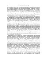
ness, scope, and underlying support technologies. Figure 7.1 graphically summarizes the
major types of requirements that we have found essential for XIML. In this section, we
discuss each of those types in detail.
Organization
Abstract
Concrete
XIML
Relational Relational
Design
Evaluation
Operation
Figure 7.1. XIML represents abstract, concrete and relational data items. It also enables user-inter-
face engineering functions.
124 ANGEL PUERTA AND JACOB EISENSTEIN
• Central repository of data. The language must enable a comprehensive, structured stor-
age mechanism for interaction data. These repositories of data may cover in scope
one user interface, or a collection of user interfaces. In this manner, purely organiza-
tional or knowledge-management functions can be supported by XIML. For example,
a cell-phone manufacturer could use XIML to store and manage all the characteristics
and design data relevant to the user interfaces for its entire line of products.
• Comprehensive lifecycle support. The language must enable support functionality
throughout the complete lifecycle of a user interface. This includes design, operation,
and evaluation phases. This requirement is critical because it will afford an engineering
framework to connect the now disjoint stages in the life of a user interface. For example,
an interface-design tool could output an XIML interface specification that can be used
at runtime for the management of interaction and that can also be the basis for usability
engineering activities.
• Abstract and concrete elements. XIML must be able to represent the abstract aspects of
a user interface, such as the context in which interaction takes place, and the concrete
aspects, such as the specific widgets that are to be displayed on a screen. This require-
ment is almost a corollary of the previous one as comprehensive lifecycle support
would not be possible without it. It is also recognition that interaction decisions – be it
in design or operation of a user interface – are dictated in great part by items such as
the task flow of a target business process or the characteristics of a specific user type.
• Relational support. The language must be able to relate the various elements captured
within the scope of its representation. This is particularly important in the case of
relating abstract and concrete elements of interaction data. The relational capabilities
of the language are what enable the development of knowledge-based support through-
out the lifecycle of a user interface [Puerta and Eisenstein 1999; Szekely et al. 1995].
For example, model-based interface development tools, interface agents, and intelli-
gent ergonomic critics are some of the technologies that can take advantage of these
relational capabilities within their reasoning processes.
• Underlying technology. In order to be useful within an industry-based new computing
model, XIML must adhere to at least two implementation requirements. First is the
use of an underlying technology that is compatible with that computing model. In
this case, this points to the use of XML – the representational centerpiece of the new
computing model – as the base language for XIML. Second, the language must not
impose any particular methodologies or tools on the design, operation, and evaluation
of user interfaces. It must be able to co-exist with existing methodologies and tools
(limited, of course, by any compatibility issues external to XIML between those tools
and methodologies, and the chosen underlying technologies). It should nevertheless be
noted that implementation issues are strictly a practical consideration for the language.
They impose certain limitations as to what can be achieved in practice, but they do not
detract from the theoretical principles of the language and its applicability to different
underlying technologies.
7.2.3. STRUCTURE AND ORGANIZATION OF XIML
The XIML language draws mainly from two foundations. One is the study of ontologies
and their representations [Neches et al. 1991] and the other is the work on interface