SolidWorks 2010 bible phần 5 doc
Bạn đang xem bản rút gọn của tài liệu. Xem và tải ngay bản đầy đủ của tài liệu tại đây (3.47 MB, 118 trang )
Part II: Building Intelligence into Your Parts
428
FIGURE 11.24
Deviation analysis of an existing part
Select
RMB then select tangency
FIGURE 11.25
Rolling back to just after the spiral
Chapter 11: Editing and Evaluation
429
5. Try to draw a horizontal line from the outer end of the spiral. You will notice that
you cannot reference the end of the spiral.
Tip
Curves that are absorbed into other features are notoriously difficult to work with. Generally, you need to
select them from the FeatureManager to do anything at all with them. Also, if you need to reference an end of
an absorbed curve, you are better off using Convert Entities to make it into a sketch entity.
n
6. Notice that you cannot select the spiral from the graphics window. Even when
selected from the FeatureManager, it appears not to be selected in the graphics window.
Ensure that it is selected in the FeatureManager, and then click the Convert Entities but-
ton on the sketch toolbar.
7. Draw a horizontal line from the outer end of the spiral and dimension it to be three
inches long, as shown in Figure 11.26.
FIGURE 11.26
Preparing for the Fit Spline
8. Select both the converted spiral and the line, and click Tools ➪ Spline Tools ➪ Fit
Spline. Set the Tolerance to .1 and make sure that only the Constrained option is selected.
Click OK to accept the Fit Spline. Test to make sure that a single spline is created by mov-
ing your cursor over the sketch to see whether the whole length is highlighted.
Note
The Fit Spline feature fits a spline to a set of sketch entities within the specified tolerance. It can be a useful
tool for smoothing out sketch geometry.
n
Part II: Building Intelligence into Your Parts
430
Caution
Do not exit the Fit Spline by pressing the Enter key as you do with other commands, because it simply exits you
out of the command without creating a spline.
n
9. Right-click on spline and select the Curvature Comb. Notice how the comb is affected
by the transition from the spiral to the straight line.
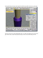
10. Exit the sketch, and create a new plane. Choose Insert ➪ Reference Geometry ➪ Plane
from the menus. Select the Right plane from the Flyout FeatureManager as the first refer-
ence and the outer end of the Fit Spline that you have just created as the second refer-
ence. Click OK to accept the new plane. This is illustrated in Figure 11.27.
FIGURE 11.27
Creating a new plane
11. Drag the Rollback bar down between Sketch3 and Loft1. If it goes beyond Loft1, then
you need to navigate back to this position again.
12. Right-click Sketch3 and select Edit Sketch Plane. Select the newly created Plane1 from
the Flyout FeatureManager, and click OK to accept the change.
13. Notice that the loft profile has moved to a place where it does not belong. This is
because the sketch has a Pierce constraint to the spiral, and there are multiple places
where the spiral pierces the sketch plane.
Edit Sketch3 and delete the Pierce constraint on the sketch point in the middle of the
construction line. Create a Coincident relation between the sketch point and the outer
end of the Fit Spline, as shown in Figure 11.28. Do not exit the sketch.
Chapter 11: Editing and Evaluation
431
FIGURE 11.28
Sketch3 in its new location
14. One of the goals of these edits is to smooth out the part. Remember that the Deviation
Analysis told you that the edges created between the lines and arcs in Sketch3 were not
very tangent. For this reason, it would be a good idea to replace the lines and arcs in
Sketch3 with another Fit Spline.
Right-click one of the solid sketch entities in Sketch3, and click Select Chain.
15. Create another Fit Spline using the same technique as in Step 8. Exit the sketch.
16. Drag the Rollback bar down one feature so that it is below the Loft. Notice that the
Loft feature has failed. If you hold the cursor over the feature icon, the tooltip confirms
this by displaying the message, “The Loft Feature Failed to Complete.”
17. Edit the Loft feature. Expand the Centerline Parameters panel if it is not already expanded,
and delete the Spiral from the selection box. In its place, select the Spiral Fit Spline.
18. If the loft does not preview, check to ensure that the Show Preview option is
selected in the Options panel, at the bottom.
19. If it still does not preview, right-click in the graphics window and select Show All
Connectors. Position the blue dots on the connector so that it looks like Figure 11.29.
20. Click OK to accept the loft. The loft should be much smoother now than it was before.
In addition, the spiral feature should no longer be under the loft; it should now be the
first item in the design tree.
21. Drag the Rollback bar down to just before the Shell feature. Notice that Fillet5 has
failed. Move the mouse over Fillet5. The tooltip tells you that it is missing some refer-
ences. Edit Fillet5 and select edges in order to create fillets, as shown in Figure 11.30.
Part II: Building Intelligence into Your Parts
432
FIGURE 11.29
Positioning the connectors
Position connector dots
in approximately corresponding
locations on the two loft profiles
22. Right-click in the design tree and select Roll To End. This causes the FeatureManager
to become unrolled all the way to the end.
23. The outlet of the involute is now longer than it should be. This is because the original
extrude was never deleted from the end. Right-click the Extrude1 feature and select
Parent/Child. The feature needs to be deleted, but you need to know what is going to be
deleted with it.
24. The Shell is listed as a child of the extrude because the end face of the extrude was
chosen to be removed by the Shell. Edit the Shell feature and remove the reference to
the face. (A Shell feature with no faces to remove is still hollowed out.)
25. If you right-click Extrude1 and select Parent/Child again, the Shell feature is no lon-
ger listed as a child.
26. Delete Extrude1, and when the dialog box appears, press Alt+F to select Also
Delete Absorbed Features.
Chapter 11: Editing and Evaluation
433
FIGURE 11.30
Repairing Fillet5
Make selections to fillet edges
27. Edit the Shell feature and select the large end of the loft. Exit the Shell feature. The
results up to this step are shown in Figure 11.31.
FIGURE 11.31
The results up to Step 27
28. Drag a window in the design tree to select the four fillet features. Then right-click
and select Add to New Folder. Rename the new folder Fillet Folder.
29. Click the Section View tool, and create a section view using the Front plane.
30. Reorder the Fillet folder to after the Shell feature.
Part II: Building Intelligence into Your Parts
434
31. At this point, you should notice that something does not look right. This is because
creating the fillets after the Shell causes the outside fillets to break through some of the
inside corners. The fillets should have failed, but have not, as shown in Figure 11.32.
FIGURE 11.32
Fillets that should have failed
32. Choose Tools ➪ Options ➪ Performance, and select Verification on rebuild. Then
click OK to exit the Performance menu and press Ctrl+Q. The fillets should now fail.
33. Click Undo to return the feature order to the way it was.
34. Save the part.
Summary
Working effectively with feature history, even in complex models, is a requirement for working
with parts that others have created. When I get a part from someone else, the first thing that I usu-
ally do is look at the FeatureManager and roll it back if possible to get an idea of how the part was
modeled. Looking at sketches, relations, feature order, symmetry, redundancy, sketch reuse, and
so on are important steps in being able to repair or edit any part. Using modeling best practice
techniques helps ensure that when edits have to be done, they are easy to accomplish, even if they
are done by someone who did not build the part.
Evaluation techniques are really the heart of editing, as you should not make too many changes
without a basic evaluation of the strengths and weaknesses of the current model. SolidWorks pro-
vides a wide array of evaluation tools. Time spent learning how to use the tools and interpret the
results is time well spent.
T
he chapters of Part III detail the tools you need to
be familiar with in order to get the most from your
assemblies. Of these, Chapters 12 and 16 are my
favorites. These are loaded with best-practice suggestions
and tips for efficient workflow. Chapter 16, the in-context
chapter, is particularly important for SolidWorks users
from many different fields who need or want to make
parametric relations between parts. A lot of erroneous
information floats around the SolidWorks community on
this topic, and this chapter will help you cull the reliable
information.
IN THIS PART
Chapter 12
Building Efficient Assemblies
Chapter 13
Getting More from Mates
Chapter 14
Controlling Assembly
Configurations and
Display States
Chapter 15
Using Component Patterns
and Mirrors
Chapter 16
Modeling in Context
Working with
Assemblies
Part III
437
CHAPTER
Building Efficient
Assemblies
IN THIS CHAPTER
Setting apart the elements of
an assembly
Increasing performance by
using SpeedPaks
Organizing assemblies by
using subassemblies
Grouping parts and mates by
using folders
Showing names and
descriptions with tree display
options
Employing helpful assembly
tools
Arranging assemblies tutorial
Managing the FeatureManager
tutorial
C
hapter 4 provides a brief introduction to the basics of assemblies,
how to put parts together, the basics of mating, and so on. The basic
process for putting assemblies together remains the same for assemblies
of any size, but once the assembly passes a certain point — and this point is
likely different for each user or application — the assembly will benefit from
some sort of organization or management techniques. This chapter introduces
you to the tools and techniques that are available to help you manage
performance issues as well as general-use issues, efficiency, browse-worthiness,
or searchability.
Identifying the Elements of an
Assembly
From Chapter 4, you know that an assembly can contain parts and mates.
Real-world assemblies can become much more complex. As the number of
parts and design requirements for an assembly grows, you may need to add
some of the following types of assembly elements. (You may already be
familiar with some of these from having worked with part documents.) The
assembly elements are listed here, and described in detail either later in this
chapter or in other chapters.
l
Assembly equations
l
Assembly Layout feature
l
Assembly layout technique
l
Assembly reference geometry (plane, axis, point, coordinate system)
Part III: Working with Assemblies
438
l
Parts
l
Subassemblies
l
Folders for parts
l
Folders for mates
l
Mates
l
Assembly features (cuts that are made once the parts are assembled)
l
Component patterns
l
Mirror components
l
In-context reference placeholders
l
Smart Fasteners
l
Smart Components
l
Virtual components
l
Envelopes
l
Assembly configurations
l
Assembly Design Table
l
Assembly Bill of Materials (BOMs)
l
Hidden/Suppressed/Lightweight/SpeedPak
l
Sensors
l
Hole Series
These elements are shown in Figure 12.1.
Standard reference geometry items
The three standard planes and the Origin in the assembly FeatureManager design tree are all
familiar to you, as are the other standard items, such as the Annotations, Design Binder, Sensors,
and Lights and Cameras folders. These items offer the same standard functionality of their part
document counterparts.
Note
Remember that you can use choose Tools ➪ Options ➪ FeatureManager page and permanently select or
deselect various folders under the FeatureManager header. Also be aware that when some folders are set to
Automatic, they do not automatically turn on when they should. In cases like this, choose Tools ➪ Options ➪
FeatureManager and manually set them to Show.
n
Chapter 12: Building Efficient Assemblies
439
Assembly equations
Assembly equations work mainly like part equations, but with some additional complications
and considerations. For example, one of the additional features of assembly equations is the ability
to drive the dimensions of one part from another part. The syntax is slightly different for this
application, as shown in Figure 12.2. Overall, issues with equation order and using driven
dimensions on the right side of the equation are the same between parts and assemblies.
FIGURE 12.1
Elements of an assembly
Cross-Reference
Equations are discussed in detail in Chapter 9.
n
FIGURE 12.2
An assembly equation driving one part from another
Part III: Working with Assemblies
440
External references
Notice the “->” symbol after the Equations folder in the Assembly FeatureManager. This means that
there is an external or in-context reference. An external reference means that an aspect of the part
is dependent upon something outside of the part. This has file management implications because
you must maintain the names of the files so that they always recognize the other file involved in
the external relation. In-context means that one part has a relation to another part in positions
determined by an assembly. So in this case, the in-context external reference can only be solved if
the original part, the referenced part, and the assembly where the relationship was created are all
open at the same time.
Cross-Reference
In-context references are discussed in depth in Chapter 16.
n
When one part drives another part in this way, the assembly must also be open to drive the
relationship. If just the two parts are open individually, then changing the driving part does not
update the driven part; because the relationship was created in the context of the assembly, the
assembly must also be open to facilitate the change.
Link values and global variables
Link values and global variables also work in assemblies, but they do not work between parts.
Local assembly sketches can use these functions, and the parts can use them when edited in the
context of the assembly, but they cannot cross any document barriers (links must remain within a
single document).
Renaming
Equations update with new part names regardless of how the part is renamed. Names of
subassemblies also update when assembly files are renamed. This includes renaming a document
using the Save As command, using SolidWorks Explorer, or using Windows Explorer. It also
includes redirecting the assembly to the new part name, as well as renaming the assembly using
each of these techniques. If the assembly can find the part and recognizes the part as the one
that it is looking for, then the equation will work.
Some of the methods named previously for renaming parts are not recommended; for testing
purposes I specifically tried to break the relationships in the equations by using them. SolidWorks
Explorer and the Save As methods can be effective when used properly. References between files
are a different issue altogether from an equation’s references to local file names.
Recommendations
While assembly equations are certainly a valid way to control part sizes, I would recommend using
assembly or part configurations, possibly with design tables, to accomplish something similar.
Equations and configurations do not mix well because the two methods compete to control the
dimensions. I recommend configurations with design tables over equations.
Chapter 12: Building Efficient Assemblies
441
Cross-Reference
Assembly configurations are discussed in Chapter 14. Design tables are discussed in Chapter 10.
n
Caution
You may have unexpected results if a single dimension is controlled from more than one location. For example,
if you have a part-level equation and an assembly-level equation, then one of the equations will be automatically
set to Read Only and will not be used.
n
Assembly layout sketch
SolidWorks has an assembly feature called Layout that uses a 3D sketch to lay out the major
functions of an assembly, and even details of parts. The word layout also refers to a technique using
2D sketches in an assembly to do exactly the same thing. The distinction between the technique and
the formal assembly feature is bound to be confusing. SolidWorks’ Layout feature only works in
assemblies, but layout techniques have been used in parts as well as assemblies for many years. In
this chapter I describe the technique, and leave the Layout feature for Chapter 16. When you look at
the two functionalities, the feature is definitely intended to be used as an in-context tool, while the
technique can be used most easily as a reference for controlling part position (through mating) rather
than a way to directly control the sizes and shapes of the parts. So when I refer to a Layout (capital),
I’m referring to the formal feature. When I refer to a layout or layout sketch (lower case), I’m referring
to a technique where a sketch is used at the assembly level to control the assembly in some way.
Cross-Reference
The Layout feature is described in more detail in Chapter 16, while the technique using assembly sketches to
lay out an assembly is described here. The material in this chapter is written as if the Layout feature does not
exist, mainly to give you a straightforward view of how the technique works without worrying about two
different functions at the same time.
n
The layout sketch is a very useful tool for laying out a mechanism in an assembly or even details
on parts within the assembly. Sketches in the assembly have the same characteristics as they do in
the part environment. In Figure 12.3, the assembly layout sketch is indicated with a heavy dashed
line for emphasis.
When combined with in-context techniques, assembly layout sketches can help to determine the
shape of parts, or the location, size, or shape of features within the parts. You can also use layout
sketches to mate assembly components to far more robust and dependable mates, rather than
mating part to part. The sketch shown in Figure 12.3 is used for both of these techniques. The
shape of the frame and the major pivot points are established in the 2D sketch. The wheels are also
mated to the sketch.
When you use an assembly layout sketch for either the in-context part building or simply part
positioning, the main advantage that it offers is giving you a single driving sketch that enables you to
change the size, shape, and position of the parts. You can use as many layout sketches as you want,
and you can make them on different sketch planes. This enables you to control parts in all directions.
Part III: Working with Assemblies
442
FIGURE 12.3
An assembly layout sketch
Caution
When using layout sketches, it is assumed that the relationships are created such that the sketch drives
everything else. However, there is nothing preventing you from using other things in the assembly to drive the
sketch. You should avoid this type of conflict, called a circular reference. It can create sketches that change
with every rebuild and can seriously impact rebuild times. When using any type of in-context relations, you
need to be careful to establish one or more driving entities, which are not in turn driven by other entities.
To take this a step further, it is best to avoid daisy chaining, where A drives B, B drives C, and so on. It is
better practice to make A drive both B and C directly. This saves on rebuild times and troubleshooting. See the
sidebar on using the skeleton or wide tree approach in Chapter 11 for more details on the benefits of this type
of modeling and an example part.
n
One of the drawbacks of this technique is that you give up dynamic assembly motion. To move the
parts, you have to move the sketch and rebuild. The part does not move until the sketch is
updated. If you need to combine layout functionality with dynamic assembly motion, see the
Layout feature in Chapter 16.
Virtual components
Virtual components are covered in more depth in Chapter 16. Virtual components are parts that
are saved so they are internal to the assembly. You can save them out so that they are external to
the assembly and can be reused in other assemblies. You can also convert external components to
virtual components. Virtual components, as the name suggests, can be either parts or subassemblies.
Chapter 12: Building Efficient Assemblies
443
Best Practice
Using virtual components is a technique that is useful for concept work in assemblies, but you will not see
them show up on any best practice list. The main limitation of this technique shows up in the form of data
management and reuse. I recommend limiting your use of virtual components because the technique promotes
what many users and administrators consider to be sloppy practice.
n
Assembly reference geometry
Planes and axes are frequently created within assemblies to drive symmetry or placement of parts.
You can use assembly layout sketches to create the reference geometry entities. When you create
reference geometry within the assembly in this way, be aware that the normal history-based parent/
child relationships are still followed. The familiar icons for reference geometry entities are also
used in the assembly tree.
History-based and non-history-based portions
of the assembly tree
Because features such as sketches and reference geometry are history based and found in the
assembly tree, at least a portion of the assembly FeatureManager is history based. However, not all
of it is. For example, the list of parts and subassemblies is not history based.
Sketches and reference geometry may appear before or after the list of parts, subassemblies, and
mates. All the remaining entity types that can be found in the assembly FeatureManager are also
history-based features, and you can reorder them in the tree. However, several situations can
disrupt the process. Under normal circumstances, sketches and reference geometry at the top of
the assembly FeatureManager are solved, then the parts are rebuilt if required, and then the mates.
This ensures that the sketches and reference geometry are in the correct locations so that if parts
are mated to them, all the components end up being the correct size and in the right position.
Assembly-level reference geometry can be created that references component geometry instead of
layout sketches. This creates a dependency that changes the usual order. For example, the planes
are usually solved before the part locations, but when the plane is dependent on the part location,
the plane has to be solved after the part. If a part is then mated to the plane, you are beginning to
create a dependency loop, such that the plane is solved, followed by the part, then the plane again
because the part has moved; and then the mate that goes to the plane has to resolve the part.
Best Practice
If you are a bit confused by all of this, don’t worry. You can simply follow this rule: Do not mate to anything
that comes after the mates in the assembly FeatureManager tree. This includes assembly planes or sketches that
are dependent on part geometry, assembly features such as cuts, in-context features, component pattern
instances, Series Holes, or Smart Fasteners.
This is probably a lot of information if you are a new user, but if you remember this rule, you can avoid
creating models with circular references, where A is dependent on B, which is dependent on A — a never-
ending loop that causes major problems for large assembly rebuild times.
n
Part III: Working with Assemblies
444
Parts and subassemblies
Parts and subassemblies are shown with their familiar icons in the design tree. You can reorder and
group them in folders, which is covered in the next section.
Parts are sometimes shown with a feather, which indicates a lightweight part, and assemblies can
have an icon that indicates a flexible subassembly.
Special icons also exist for hidden and suppressed components.
Folders
You can create folders to organize and group both parts and mates. I discuss this technique in
detail later in this chapter.
Mates
The Mates area remains a constant, single folder, but you can organize it by reordering the mates
and grouping them into folders. Each mate is shown with a symbol corresponding to the type of
mate it is, but the mate folder is shown as a pair of paperclips.
Assembly features
In manufacturing, once parts are assembled, secondary machining operations are sometimes
applied to them to ensure that holes line up properly, or for other purposes. For example, assembly
features can be cut extrudes, cut revolves, or hole features. These features appear only in the
assembly, not in the individual parts.
You should not confuse assembly features with in-context features. In-context features are created
when you are editing a part in the assembly with a reference between parts, but the sketch and
feature definition are in the part itself.
Component patterns and mirror components
Component patterns can pattern either parts or assemblies by creating either a pattern defined in
the assembly, or a pattern that follows a pattern feature created in a part. The pattern is listed as
a feature in the assembly FeatureManager, and all the instance parts appear indented from the
pattern feature in the design tree. You can hide or suppress each instance, change its configuration,
and in most ways control it as if it were a regular part in the design tree.
Because the options for locally defined patterns are comparatively limited, users generally like to
use part feature patterns to drive the component patterns when possible.
Chapter 12: Building Efficient Assemblies
445
Component patterns are listed at the bottom of the assembly FeatureManager with a set of
components under a LocalPattern icon. The component instances under the LocalPattern can be
controlled in several ways, including assigned configurations, colors, and display states. The
pattern can even be dissolved, leaving the components, but dissolving the intelligent pattern that
places them.
Mirror components are revamped in 2010 and are also listed under a special MirrorComponent
icon after the mates.
Performance
To improve performance, it is best to pattern subassemblies if possible. If it is not possible, then patterning a
group of parts is the next best option. Making multiple patterns, one for each part, is an inefficient way to
accomplish the same thing.
n
In-context reference update holders
It is difficult to get a good picture of assemblies in general without including a discussion about
in-context references, but to treat the subject properly, it also requires its own section, and in fact,
this book gives in-context modeling its own chapter (Chapter 16). When you create a reference
between parts in an assembly, the assembly needs to remember which parts are involved in the
reference, and what assembly creates the spatial relationship between them.
When you create the relation, a placeholder has to remain in the assembly to hold this information.
This placeholder is called an Update Holder. The Update Holders do not display by default. To see
them, you must right-click the top level in the FeatureManager and select Show Update Holders.
They only exist when in-context references exist in the assembly, and there is one Update Holder
for each in-context sketch or feature. You cannot do very much with the Update Holders, other
than query them for parent/child relations and to list the external relations, but they serve as a
reminder that you have in-context references to maintain. For more information on this feature,
see Chapter 16.
Popular perceptions of in-context techniques aside, in-context modeling is a powerful extension of
parametric design techniques. If you follow the best practice suggestions outlined in Chapter 16,
you will soon gain confidence and master this technique rather than being frightened by it. The
functionality works, and if you do not abuse it, it will serve you well.
Smart Fasteners
Smart Fasteners are assembly features that automatically select Toolbox parts for use in standard-
sized holes, and you can use them in many different ways. The Smart Fastener feature in the
assembly FeatureManager is used to edit the definition of the Smart Fastener, which can include
adding items such as nuts and washers. You can also use Smart Fasteners in conjunction with the
Hole Wizard to place appropriate holes and matched fasteners, all in a single step.
Part III: Working with Assemblies
446
Cross-Reference
Smart Fasteners, Toolbox, and the Hole Wizard are discussed in detail in Chapter 17. This is the only
functionality beyond what is found in SolidWorks Standard edition that I deal with in this book.
n
Hole Series
The Hole Series is a Hole Wizard–type feature that you apply in an assembly. This wizard leaves
the feature icon in the assembly, but also adds features directly to the individual parts. It also adds
in-context Update Holders to the assembly FeatureManager, as shown in Figure 12.4. The Series
Hole is designed to go through a series of parts, placing the appropriate hole type in each part,
counterbore, through, threaded, and so on.
FIGURE 12.4
Adding in-context Update Holders
Chapter 12: Building Efficient Assemblies
447
Using SpeedPaks
A SpeedPak is a derived configuration of an assembly that keeps only selected solid bodies and
faces, but can represent the rest of the assembly with non-selectable display data. A SpeedPak can
be used to replace an entire subassembly within an upper-level assembly. SpeedPaks are intended
to increase performance with very large assemblies and drawings.
Figure 12.5 shows first the SpeedPak PropertyManager, which you access by right-clicking an
active configuration, and selecting Add SpeedPak. Each configuration can have only one SpeedPak.
Figure 12.5 also shows the configuration list with the SpeedPak listed indented under the Default
config, and the entire assembly. The final image shows the SpeedPak inserted into an assembly
document, consisting of a single face and two solid bodies. Notice the special icon associated with
SpeedPaks. You can change a part in an assembly from or to a SpeedPak in the same way that you
would change a configuration using Component Properties.
Remember this is a tool for increasing assembly speed, and to increase speed, there is always
something that you have to give up. SpeedPak can be thought of in some ways like Lightweight
assemblies and components in that it is display-only data. If your expectations of the tool are in
line with the actual functionality, you will be very satisfied with the functionality SpeedPaks offer.
For this reason it is important to understand the abilities and limitations of SpeedPak.
Using ghosts
You can use any faces or bodies that you select in the Include lists either manually or through the
Quick Include sliders (which automatically select bodies and faces based on size) in assemblies to
mate to or in drawings to dimension to. Any geometry that is not selected is included as a ghost —
it displays, but cannot be selected. When the cursor gets near ghost geometry, the ghost fades
away, revealing only selectable geometry. Notice at the bottom of the SpeedPak PropertyManager
that you can also choose to remove the ghost data and further increase the memory savings.
Sharing self-contained data
The SpeedPak is self-contained. All the selected face and body geometry is saved inside the
assembly. If you want to send someone a visual representation of an assembly, make a SpeedPak
configuration and send only the assembly file — no parts are required. This is the equivalent of
being able to put an eDrawing file into an assembly.
Using SpeedPak with drawings
You can even use SpeedPaks with drawings. Just remember that only edges created by the faces or
bodies in the Include lists can be dimensioned to. Some functionality exists for the ghost data,
such as BOM inclusion and numbered balloons. Ghost data displays as gray on the drawing, while
geometry in the Include list is black.
Part III: Working with Assemblies
448
FIGURE 12.5
Managing SpeedPaks
Model of Garmin assembly from the SolidWorks demo sets
Chapter 12: Building Efficient Assemblies
449
Using Subassemblies
The primary tool for organizing assemblies is the subassembly. A subassembly is just a regular
assembly that is used as a component in another assembly.
Best Practice
The number of levels of subassemblies is not limited to a specific number, although for different sizes and types
of assemblies, I encourage you to establish a best practice for your company. For example, establish a guideline
that suggests that subassemblies of 100 parts or less go no deeper than three levels.
n
You can use several criteria to determine how subassemblies are assigned:
l
Performance
l
BOM
l
Relative motion
l
Pre-fabricated, off-the-shelf considerations
l
According to assembly steps for a process drawing
l
To simplify patterning
The underlying question here is based on the multiple functions of your SolidWorks assembly
model. Is the assembly intended primarily for design? For visualization? For documentation? For
process documentation? When used primarily for design, the assembly is used to determine fits,
tolerances, mechanisms, and many other things. As a visualization tool, it simply has to look good
and possibly move properly if that is part of the design. As a documentation tool, it is important
how the model relates to the BOM, and the order in which subassemblies are added. As a process
tool, you need to be able to show the assembly in various intermediate states of being assembled,
likely with configurations.
I have seen companies create multiple assembly models for different purposes. Sometimes the
requirements between the different methods are contradictory and cannot all be met at the same
time with a single set of data. Again, depending on what information you need to be able to extract
from your SolidWorks models, you may want to approach assembly modeling and organization
differently, and you may need to create multiple assembly models to accomplish everything.
Creating subassemblies from existing parts
You can create subassemblies from parts that already exist in an assembly. To do this, select the
parts that you want to add to the subassembly using Shift+, Ctrl+, or box select techniques, and
then select Form New Subassembly Here from the right mouse button (RMB) menu. You are then
prompted to assign a name or possibly select a template for the new subassembly.
Part III: Working with Assemblies
450
Caution
When creating a new subassembly from existing parts or when moving parts into or out of a subassembly from
the upper-level assembly, some things may be lost. For example, mates are moved from the upper level to the
subassembly. If you have in-context relationships, they may be removed. Operations that create subassemblies
cannot be undone easily.
n
Once you have created the subassembly, you can add or remove components using the drag-and-
drop method. For example, Figure 12.6 shows the cursor that indicates that the part named Left
Crank is being moved into the subassembly named bike crank. To move a part out of a subassembly,
simply drag the part into the upper-level assembly.
FIGURE 12.6
Moving parts into a subassembly
Note
When you are dragging a part out of an assembly and into another one, you may again see the cursor symbol
that appears in Figure 12.6. If you do not want this to happen, hold down the Alt key while dragging. The
cursor symbol changes to the Reorder cursor (a reversed, L-shaped arrow), and the part is placed after the
subassembly rather than within it.
n
Insert a new subassembly
Along with the RMB menu option Form New Subassembly Here, which takes existing parts and
puts them into a newly created subassembly, you can use another option called Insert New
Subassembly. The names of these functions do not adequately describe the difference in what they
do. Insert New Subassembly inserts a blank subassembly at the point in the design tree that you
indicate by right-clicking it. You can place components into the subassembly by dragging and
dropping them from the main assembly, or you can open the assembly in its own window and
insert parts by using the usual methods.
Dissolving subassemblies
If you would like to get rid of a subassembly but want to keep its parts, then you can use the
Dissolve Subassembly option through the RMB menu. This option has some of the same consequences
of the Form New Subassembly Here option in that mates are moved from the subassembly to the
upper-level assembly, and you may lose in-context relations and assembly features.
Chapter 12: Building Efficient Assemblies
451
Organizing for performance
Performance in SolidWorks is a word used to mean speed. Subassemblies can contribute to speed-
saving modeling techniques by segmenting the work that the software needs to do at any one time.
Solving mates
The mates that contribute to putting the pieces of an assembly together are solved at the level of
the top assembly. Under normal circumstances, subassemblies are treated as static selections of
parts that are welded together, and their mates are not solved at the same time that the top-level
assemblies’ mates are solved. This segmenting of the mates leads to improved performance by only
solving one set of mates at a time.
Mates are usually solved as a single group unless there is a special situation, such as mates to
in-context features, component pattern instances, or an assembly feature, all of which have already
been described in this chapter. When one of these situations occurs, the mates have to be divided
into separate groups or solved multiple times. This is done transparently behind the scenes so that
the user does not have to worry about it. Multiple rebuilds affect the user only in terms of rebuild
times.
Flexible subassemblies
When you create subassemblies, the mates for the parts of the subassembly are not solved in the
upper-level assembly. This means that if a subassembly is a mechanism, the mechanism does not
allow Dynamic Assembly Motion in the upper-level assembly. For example, in Figure 12.7, the
front fork is a linkage mechanism, but it is also a subassembly. Without reassembling the parts of
the fork in the upper-level assembly, you can allow the mates from the fork subassembly to be
solved in the upper-level assembly by using the Flexible Subassembly option in the Component
Properties dialog box, which is also shown in Figure 12.7. When you select the Flexible option in
the Solve As section, you enable the mates of this subassembly to be solved in the upper-level
assembly, which allows the parts of the subassembly to move in the upper-level assembly.
To access the Component Properties dialog box, right-click the subassembly and select Component
Properties from the menu.
Flexible subassemblies have become more reliable and easier to use over the last several releases. I
encourage you to work with them or do some experimentation to see if they assist your modeling
process. If you find they cause trouble in some situations, they are easy enough to simply deactivate.
Legacy data
If you have assemblies that were built in older versions of SolidWorks (such as SolidWorks
2001+), mates used to be split up into multiple mate groups, which represented the groupings that
mates were solved in. This was forced by mating to the history-based features in the assembly
FeatureManager. SolidWorks no longer displays mate groups, but the groups are still used in the
background to solve mates. This is another change that SolidWorks has made to the software that
simplifies the user’s interaction with the software, but also makes it obvious that things are now
happening behind the scenes that you can’t control.