Colonoscopy Principles and Practice - part 5 pot
Bạn đang xem bản rút gọn của tài liệu. Xem và tải ngay bản đầy đủ của tài liệu tại đây (1.7 MB, 67 trang )
258 Section 6: Hardware
the control of remote devices easily accessible? Does
the size and weight of the equipment allow for easy
transportation?
7 System expansion and integration. Is the system cap-
able of easily interfacing with hard-copy devices, video-
tape recorders, and computerized image management
systems?
Summary
During the 1990s, the video-image colonoscope sup-
planted the fiberoptic colonoscope as the preferred
instrument for colonoscopy. The availability of two
distinct technologies for generating color images (color-
chip vs. RGB sequential) provides the endoscopist with
a choice of basic systems, each with its own advant-
ages and disadvantages. Although the basic shape and
function of the instrument have remained unchanged,
recent advancements (including the development of
smaller-diameter insertion tubes, instruments with ad-
justable stiffness, improvements in image resolution,
and advanced video processor features) have continued
the evolution of the colonoscope.
References
1 Moriyama H. Engineering characteristics and improvement
of colonoscope for insertion. Early Colorectal Cancer 2000; 4:
57–62.
2 Moriyama H. Variable stiffness colonoscope: structure and
handling. Clin Gastroenterol 2001; 16: 167–72.
3 Kawahara I, Ichikawa H. Flexible endoscope technology: the
fiberoptic endoscope. In: Sivak MV Jr, ed. Gastroenterologic
Endoscopy, 2nd edn, Vol. 1. Philadelphia: WB Saunders, 2000;
16–28.
4 Barlow DE. Flexible endoscope technology: the video image
endoscope. In: Sivak MV Jr, ed. Gastroenterologic Endoscopy,
2nd edn, Vol. 1. Philadelphia: WB Saunders, 2000; 29–49.
5 Sivak MV Jr, Fleischer DE. Colonoscopy with a video endo-
scope. Preliminary experience. Gastrointest Endosc 1984; 30:
1–5.
6 Knyrim K, Seidlitz H, Vakil N et al. Optical performance of
electronic imaging systems for the colon. Gastroenterology
1989; 96: 776–82.
7 Schapiro M. Electronic video endoscopy. A comprehensive
review of the newest technology and techniques. Pract
Gastroenterol 1986; 10: 8–18.
8 Anonymous. Video colonoscope systems. Health Devices
1994; 23: 151–205.
259
Introduction
The colonoscope insertion tube is the largest contributor
to overall endoscope performance. Individual practi-
tioners develop a preference for individual instruments
and develop skill and techniques for their use. Many
choose soft flexible insertion tubes for their ability to
maneuver through the sigmoid colon easily. However,
advancement beyond the splenic flexure can prove
challenging, requiring a variety of maneuvers, including
patient positioning and counterpressure. Alternatively,
stiffer instruments may be preferred for the opposite
reason. Some endoscopists accept a more difficult sig-
moid negotiation with stiffer instruments in order to
permit easier cecal access once the splenic flexure has
been negotiated. Examinations with stiffer instruments
understandably may require more patient sedation, but
there has not been a higher perforation rate reported
with their use.
Various instruments
Pediatric-diameter long-length colonoscopies were intro-
duced in the late 1980s and reports of successful use in
adults soon followed. In 70 of 72 cases where the sigmoid
could not be negotiated using standard colonoscopes,
Bat and Williams [1] reported success with pediatric
instruments. Reasons for initial failures included stric-
tures, severe diverticular disease, and postoperative
adhesions.
Several authors have now concluded that women
are more difficult to examine at colonoscopy, especially
if they have undergone hysterectomy, and are most
likely to benefit from the use of pediatric endoscopes
[2,3]. In a randomized trial of 100 women with hysterec-
tomies, Marshall and colleagues [4] reported success-
ful entry into the cecum in 96% when using pediatric
colonoscopes compared with only 71% where stand-
ard colonoscopes were employed. When these failures
with standard colonoscopes were then attempted with
pediatric instruments, more than half could be success-
fully completed. Nevertheless, most endoscopists who
use pediatric colonoscopes have observed that keep-
ing the instrument straight and advancing beyond the
splenic flexure may be difficult. This should not be
unexpected in view of the thin flexible insertion shaft of
pediatric instruments.
When the more flexible endoscopes loop and bend
during intubation, counterpressure and/or patient re-
positioning are the most frequently employed maneuvers
to help advance the instrument. While these techniques
do not add stiffness to the colonoscope shaft, counter-
pressure does result in compression of loops to transfer
forward motion of the instrument to the tip [5]. Plac-
ing the patient on the back or right side can similarly
affect insertion, and positional changes are frequently
employed when using pediatric equipment. However,
these techniques may be ineffective due to patient body
habitus, incorrect placement of pressure, adhesions, and
looping under the ribcage in either the splenic or hepatic
flexures.
On occasion, the push enteroscope has been employed
in an attempt to complete a failed colonoscopy. The
largest experience was reported after failure with a
standard-diameter colonoscope. In 32 such cases, the
enteroscope was advanced to the cecum in 22 (68.7%),
raising the authors’ overall success rate to 96.4%. Of
note, the authors did not attempt these patients with
pediatric equipment and their report predates the avail-
ability of variable-stiffness technology [6].
The enteroscope probably does have a role in colono-
scopy on occasion. In a 2002 report, Rex and Goodwine
[7] used the enteroscope with a straightener or the colo-
noscope with a straightener to successfully study 2 of 42
consecutive patients with failed prior colonoscopies. In
my personal experience, patients with extremely long
colons with redundant sigmoids are the group in whom
previously failed colonoscopy will be successfully com-
pleted with an enteroscope. One report of the routine
use of an enteroscope rather than a colonoscope to spe-
cifically examine the terminal ileum had disappointing
results, in that the technical failure rate for ileal intuba-
tion was 33%, attributed to the length of the scope, its
smaller diameter, and its tendency to continuously form
loops [8].
Some authors have described the use of gastroscopes
in colonoscopy but, in general, only for special circum-
stances and almost always for left colon examinations
Chapter 23
The Colonoscope Insertion Tube
Douglas A. Howell
Colonoscopy Principles and Practice
Edited by Jerome D. Waye, Douglas K. Rex, Christopher B. Williams
Copyright © 2003 Blackwell Publishing Ltd
260 Section 6: Hardware
[7]. Gastroscopes have short bending segments, short
transition zones, and stiff short insertion tubes, mak-
ing them poor instruments for colonoscopy. Very slim
pediatric gastroscopes are useful for performing retro-
flexion endoscopy in the rectum and distal sigmoid to
assist in difficult polypectomy but advancement be-
yond the splenic flexure has rarely been reported. Perhaps
the most frequent use of small-caliber gastroscopes is
negotiation through severe diverticular disease, with
tortuosity of the colonic lumen, narrowing, and rigidity.
A short bending segment colonoscope in prototype
form (Olympus, Japan) has been developed to attempt to
take advantage of the tight U-turn capability of gastro-
scopes. With a pediatric insertion tube and a bending
section similar to a pediatric gastroscope, the prototype
can be easily retroflexed virtually anywhere in the colon
including in the cecum. Whether this instrument can be
as successfully passed to the cecum and whether this
ability will add to diagnostic yields or polypectomy suc-
cess will require further study.
Stiffeners
Devices to add stiffness to assist in negotiating beyond
the splenic flexure have a long history. These include
external overtubes and internal biopsy channel devices.
Overtubes were introduced in 1983 to splint the sig-
moid colon. Made of rigid tubular plastic, these devices
proved painful, cumbersome, and dangerous. A major
disadvantage was the need to withdraw the colonoscope
to load the earliest overtubes and then repeat the inser-
tion to the splenic flexure. A split overtube was mar-
keted to avoid this specific disadvantage but the original
drawbacks remained, resulting in abandonment of the
technique. Overtubes for colonoscopy are no longer
marketed.
Internal stiffening devices were initially tightly closed
biopsy forceps, which did not add sufficient additional
stiffness to reliably improve success during colon in-
tubation. First appearing in 1972, several stainless steel
cable devices where tension could be varied with a
twist-wheel were produced and marketed (Fig. 23.1).
Although often of benefit in performing a successful pro-
cedure, the devices were cumbersome, blocked suction
capabilities, and were hard to clean. Despite their limited
success in stiffening the colonoscope shaft, they were
abandoned because of their potential to cause endoscope
damage [9]. The last such device (Sullivan Stiffener,
Wilson-Cook Medical, Winston-Salem, NC) is no longer
manufactured but still exists in many units [10].
Some endoscopists prefer a double-channel colono-
scope for a stiffer insertion tube, offered by all three
major endoscopy manufacturers. The second channel
adds approximately 1 mm to the overall diameter but
increases the stiffness considerably. The additional
channel can be used to ensure suction capabilities when
the first channel is occluded by a device. Several second-
channel techniques have been used to assist in poly-
pectomy, especially collecting resected polyp specimens
while additional polyps are being removed. Never pop-
ular, these endoscopes have largely been abandoned
with the advent of graduated stiffness insertion tubes
and newer innovations that permit increasing stiffness
during colonoscopy. Nevertheless, double-channel colo-
noscopes are still produced and are currently available.
Variable-stiffness colonoscopes
Since no one stiffness is appropriate in all settings, the
development of variable-stiffness adjustment in colono-
scopes was greeted as a welcome new innovation in
endoscope engineering. Marketed by Olympus America
(Melville, NY) as Innoflex® (i.e. “innovation in flexibil-
ity”), this new colonoscope series permits adjustment of
the instrument during the procedure from flexible to stiff
using a hand dial (Fig. 23.2). The details of the engineer-
ing and manufacture are outlined in Chapter 22 but, in
summary, these instruments permit adjustment in the
range from the most flexible to the stiffest colonoscopes
currently in use (Fig. 23.3). It is important to note that the
variable-stiffness cable within the insertion tube con-
nects at 16 cm behind the tip. Tightening the internal
cable does not change the characteristics of the bending
section or the adjacent transition section (present in all
modern endoscopes). Insertion shafts have always been
produced to be stiffer than the initial forward section of
the colonoscope, producing so-called graduated stiff-
ness. This is in contrast to the ability to vary the stiffness
of the insertion shaft during the procedure by chang-
ing the tension on a variable-stiffness cable. Innoflex®
colonoscopes are produced in both standard diameter
Fig. 23.1 Early cable internal stiffening device.
Chapter 23: The Colonoscope Insertion Tube 261
(12.8 mm) and pediatric diameter (11.3 mm). The per-
formance of these insertion tubes depends upon both
the external diameter as well as length of bending sec-
tion and the degree of stiffness dialed into the variable-
stiffness portion of the insertion tube. The radius of the
bending section is shorter in pediatric instruments,
which assists in negotiating sharp turns and contributes
to its greater flexibility.
Technique for use of variable-stiffness
instruments
The recommended technique for using the variable-
stiffness colonoscope is as follows.
1 The instrument is inserted in its maximally flexible
mode (dial set at zero). The sigmoid is negotiated until
the splenic flexure is achieved and “hooked” by entering
the transverse colon. Counterpressure and/or patient
positioning may be needed during this phase.
2 The instrument is then straightened by withdrawal,
generally with some clockwise torque until about 55–
65 cm of colonoscope remains within the patient as
measured at the anal verge.
3 The dial is then twisted, fully tensioning the dial to a
setting of 3. Shaft stiffness is not a linear function so that
a setting of 1 or 2 does little to affect the character of the
insertion tube.
4 Once fully straightened and stiffened, advancement
should be facilitated. Even with the instrument in the
maximal-stiffness mode, loops can develop in the shaft
during insertion. The standard “straightening by with-
drawal” techniques should be performed frequently,
after removing the tension on the stiffening apparatus.
5 Following straightening, the above procedures can be
repeated.
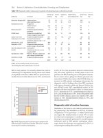
Variable-stiffness colonoscopes have rapidly gained
favor, although the literature addressing effectiveness
has reported mixed results (Table 23.1). Earlier reports
suggested that the variable-stiffness instrument signific-
antly reduced insertion time and was more comfortable
Fig. 23.2 Adjustable hand dial for adding stiffness.
CF-Q160/Q140/1T140/100T
Stiffness
level
Stiff
Flexible
Insertion tube outer diameter (mm)
Existing Olympus colonoscopes
11 11.5 12 12.5 13 13.5
PCF-140
CF-Q160L+ST-C3
CF-Q160A
PCF-160A
*
*
Fig. 23.3 Variable-stiffness graph of
pediatric (PCF160A) and standard
(CF-O160A) colonoscopes.
262 Section 6: Hardware
compared with conventional colonoscopes [11,12]. Some
later reports have agreed that counterpressure and posi-
tioning is less often needed, supporting the concept that
variable-stiffness instruments do control loop forma-
tion; however, their use did not shorten insertion time
or improve success [13,14]. Rex [15] reported a series
of patients where success and speed to the cecum was
not improved with variable-stiffness colonoscopes, but
judged the effectiveness of the stiffening device to be
very useful in 40% of cases when he used the standard-
diameter variable-stiffness colonoscope and 54% of
pediatric variable stiffness cases.
Howell and colleagues [16] compared standard and
pediatric colonoscopes with variable-stiffness standard-
diameter and pediatric-diameter colonoscopes in 600
patients. Consecutive patients were examined with either
instrument as equipment became available. The results
again demonstrated that women were more difficult to
examine and had more discomfort than men during
colonoscopy but fared better with pediatric equipment.
The use of variable-stiffness colonoscopes resulted in less
loop formation as assessed by decreased need for counter-
pressure. Patients who had undergone prior colonoscopy
with a standard adult colonoscope rated the pediatric and
variable-stiffness equipment most favorably (Fig. 23.4).
In addition, the pediatric variable-stiffness colonoscope
was given the best rating by the author, as measured by
the subjective score used.
Shumaker and colleagues [17], using a similar study
protocol, did not find any significant advantages to using
variable-stiffness colonoscopy compared with stand-
ard instruments. Nevertheless, they reported that the
variable-stiffness colonoscopes performed well and con-
cluded that further study might identify subgroups in
whom the variable-stiffness instruments would be of
benefit. Most recently, Yoshikawa and colleagues [18]
studied patients undergoing sedationless colonoscopy
and reported a significant reduction in pain scores when
using variable-stiffness pediatric colonoscopes. In this
setting cecal intubation times by the less experienced
colonoscopists were shorter than with conventional
instruments.
Recently, the newly released magnetic endoscope
imaging (MEI) device (see Chapter 24) has been used
with variable-stiffness colonoscopes. The examinations
performed with MEI demonstrated surprisingly effect-
ive control of sigmoid loop reformation after straighten-
ing and applying stiffness when the tip was at the splenic
flexure. Despite the control of looping in the sigmoid
colon, some examinations may remain challenging due
to splenic flexure looping or transverse colon redund-
ancy. Combining variable-stiffness technology with MEI
is likely to be a major step toward more effective, more
comfortable colonoscopy.
Choice of instruments
Now that many variations of insertion tubes are avail-
able, how does an endoscopist select an instrument
which is most likely to be successful for cecal intubation
Table 23.1 Variable-stiffness compared with regular colonoscopes.
Reference Patients Trial Loop control* Pain scores Time to cecum
Brooker et al. [11] 100 VSS vs. SC NA Less Less
Sorbi et al. [13] 50 VSS vs. SC Improved Less Same
Rex [15] 358 VSS vs. VSP vs. SC vs. PC Same Same Same
Howell et al. [16] 600 VSS vs. VSP vs. SC vs. PC Improved Least with PC Same
Shumaker et al. [17] 363 VSP vs. SC vs. PC Same Same Same
Yoshikawa et al. [18] 467 VSS vs. SC Same Less Less
NA, not available; PC, pediatric colonoscope; SC, standard colonoscope; VSP, variable stiffness pediatric; VSS, variable stiffness
standard diameter.
* Need for counterpressure or patient repositioning.
C PC VSC PVSC
Scope
80%
60%
40%
20%
0%
C vs PC (p<0.001),C vs VSC (p=0.001),
C vs PVSC (p<0.001)
Better
Worse
Same
Fig. 23.4 Patient comparison to their
prior colonoscopy.
Chapter 23: The Colonoscope Insertion Tube 263
and provide the greatest patient comfort? Anderson
and colleagues [19] recently studied 802 consecutive
patients in an attempt to define factors that might predict
a difficult colonoscopy. The parameters of female sex,
low body mass, diverticular disease (at least in women),
and older age all resulted in somewhat more difficult
examinations. Large body size was associated with a
somewhat easier examination.
In our endoscopy unit, pelvic surgery in thin women
causes us to select pediatric equipment, but we still
anticipate a somewhat more difficult examination and
a higher risk of failure. Conversely, obese patients are
somewhat easier to examine, probably because intra-
abdominal fat separates bowel loops, widening the radius
of sharp bends. However, the presence of a very large
panniculus often prevents effective counterpressure
when a loop is encountered. In addition, very large indi-
viduals not unexpectedly have very large colons, which
may make intubation proximal to the splenic flexure
particularly challenging. We would choose the stiffest
instrument available for use in these patients. Our choice
is a standard-diameter variable-stiffness colonoscope
when the patient’s body mass index is greater than 30.
Most patients tolerate colonoscopy very well provid-
ing that the technique employed is gentle, with frequent
straightening of early loop formation. Therefore in the
average sedated adult patient, the selection of the inser-
tion tube does not appear to make a critical difference.
What would be the ideal insertion tube of the future?
A colonoscope ultimately adjustable throughout its
length to permit painless and therefore sedationless
colonoscopy should be the future goal. Avoiding medi-
cation shortens procedure and recovery time, avoids
adverse effects of medication, and should reduce costs.
As in sigmoidoscopy, patients can drive and resume
their daily routine following sedationless colonoscopy,
greatly easing the burden to the patient and placing
colonoscopy more in line with the requirements of
screening. However, unsedated colonoscopy that results
in pain risks patient dissatisfaction. Clearly progress
toward this possibility has been made [14,18]. The cap-
ability of stiffening a specific region of the instrument
(to control looping) while simultaneously adding more
flexibility in another region (to negotiate sharp flexures)
may become possible. MEI may be required to guide this
type of alternating variable stiffness. Automatic stiffness
adjustments using internal pressure sensors might some
day be developed [20]. However, more engineering will
be required if painless colonoscopy is to be performed
uniformly and predictably in the future.
Summary
Many changes in colonoscope insertion tube design
have been developed since colonoscopy was first intro-
duced. The shaft of the instruments have become thinner
and torque stability has increased. A wide variety of per-
formance characteristics have been built into the inser-
tion tube, most of which are invisible to the user. The
variety of degrees of stiffness, the ability to vary the flex-
ibility of the shaft, and the choice of various diameters is
associated with new dilemmas for the colonoscopist.
Which instrument is best for any particular patient, and
if only one is to be purchased which one should it be?
Engineering has not yet provided the ideal instrument
but advances are made frequently. Variable-stiffness
instruments are the harbingers of a future generation of
colonoscopes that will make the procedure easier, safer,
and better tolerated.
References
1 Bat L, Williams CB. Usefulness of pediatric colonoscopes
in adult colonoscopy. Gastrointest Endosc 1989; 35: 329–32.
2 Saunders BP, Fukumoto M, Halligan S et al. Why is colo-
noscopy more difficult in women? Gastrointest Endosc 1996;
43: 124–6.
3 Saifuddin T, Trivedi M, King PD et al. Usefulness of a pedi-
atric colonoscope for colonoscopy in adults. Gastrointest
Endosc 2000; 51: 314–17.
4 Marshall JB, Perez RA, Madsen RW. Usefulness of a pedi-
atric colonoscope for routine colonoscopy in women who
have undergone hysterectomy. Gastrointest Endosc 2002; 55:
838–41.
5 Waye JD, Yessayan SA, Lewis BS et al. The technique of
abdominal pressure in total colonoscopy. Gastrointest
Endosc 1991; 37: 655.
6 Lichtenstein GR, Park PD, Long WB et al. Use of a push
enteroscope improves ability to perform total colonoscopy
in previously unsuccessful attempts at colonoscopy in adult
patients. Am J Gastroenterol 1999; 94: 187–90.
7 Rex DK, Goodwine BW. Method of colonoscopy in 42 con-
secutive patients presenting after prior incomplete colono-
scopy. Am J Gastroenterol 2002; 97: 1148–51.
8 Belaiche J, Van Kemseke C, Louis E. Use of the enteroscope
for colo-ileoscopy: low yield in unexplained lower gastroin-
testinal bleeding. Endoscopy 1999; 31: 298–301.
9 Ruffolo TA, Lehman GA, Rex D. Colonoscope damage from
internal straightener use. Gastrointest Endosc 1991; 37: 107–
8.
10 Sullivan MJ. Variable stiffening device for colonoscopy.
Gastrointest Endosc 1990; 36: 642–3.
11 Brooker JC, Saunders BP, Shah SG et al. A new variable stiff-
ness colonoscope makes colonoscopy easier: a randomized
controlled trial. Gut 2000; 46: 801–5.
12 Odori T, Goto H, Arisawa T. Clinical results and develop-
ment of variable-stiffness video colonoscopes. Endoscopy
2001; 33: 65–9.
13 Sorbi D, Schleck CD, Zinsmeister AR et al. Clinical ap-
plication of a new colonoscope with variable insertion
tube rigidity: a pilot study. Gastrointest Endosc 2001; 53:
638–42.
14 Shah SG, Brooker JC, Williams CB et al. The variable
stiffness colonoscope: assessment of efficacy by magnetic
endoscope imaging. Gastrointest Endosc 2002; 56: 195–201.
264 Section 6: Hardware
15 Rex DK. Effect of variable stiffness colonoscopes on cecal
intubation times for routine colonoscopy by an experienced
examiner in sedated patients. Endoscopy 2001; 33: 60–4.
16 Howell DA, Ku PM, Desilets DJ et al. A comparative trial of
variable stiffness colonoscopes. Gastrointest Endosc 2001;
222; 55 (4, Part 2): AB58.
17 Shumaker DA, Zaman A, Katon RM. A randomized con-
trolled trial in a training institution comparing a pediatric
variable stiffness colonoscope, a pediatric colonoscope, and
an adult colonoscope. Gastrointest Endosc 2002; 55: 172–9.
18 Yoshikawa I, Honda H, Nagata K et al. Variable stiffness
colonoscopes are associated with less pain during colono-
scopy in unsedated patients. Am J Gastroenterol 2002; 97:
3052–5.
19 Anderson J, Messina C, Cohn W et al. Factors predictive of
difficult colonoscopy. Gastrointest Endosc 2001; 54: 558–62.
20 Appleyard MN, Mosse CA, Mills TN et al. The measure-
ment of forces exerted during colonoscopy. Gastrointest
Endosc 2000; 52: 237–40.
265
Introduction
“Seeing is believing” is a saying pertinent to the colono-
scopist. The amazingly detailed views obtained during
video colonoscopy have dramatically improved our
understanding and management of many colonic dis-
eases. Understandably, much emphasis has been placed
on the development of the fiberoptic and then video
color image to identify and accurately document colonic
pathology. However, it is perhaps surprising that it
has taken until the 21st century to develop an effective
method to image and gui
de endoscope insertion through
the often tortuous intestine. Magnetic endoscope
imaging, now commercially available as Scope-guide
(Olympus Optical Company), for the first time provides
real-time three-dimensional views of the colonoscope
shaft during insertion and imparts a new understanding
for the endoscopist of the procedure and all its attendant
difficulties. It does not make a difficult colonoscopy
immediately easy and is no substitute for good tech-
nique, but does show the exact problem encountered
and gives the endoscopist a new insight into the likely
maneuvers required to straighten the endoscope and
ensure total colonoscopy.
Need for imaging
Colonoscopy is established as the procedure of choice
for investigating patients with colonic symptoms and
for screening patients considered at risk for colorectal
cancer. In recent years it has also emerged as a viable
method for population screening, with recommenda-
tions for a colonoscopy every 10 years from age 50 years
[1]. This imparts a burgeoning colonoscopic workload
and imposes a heavy duty of care on the endoscopist,
who must provide a complete, safe, and accurate exam-
ination. Expert centers for colonoscopy report comple-
tion rates, corrected to exclude obstructing lesions and
failed bowel preparation, of 97–99%, with very few if
any co
mplications from routine insertion. However less
skilled endoscopists fare considerably worse and a
recent audit from the British Society of Gastroenterology
of 9000 procedures has shown cecal intubation rates
of just 55–77% with perforation rates of 1 in 1000 pro-
cedures (O. Epstein, personal communication). These
results are unlikely to be only a British phenomenon
and are probably representative of “average” practice
throughout the world. Even experienced colonoscopists
find colonoscopy technically difficult in 10–20% of
patients [2]. The most common cause of difficulty is
recurrent shaft looping with
in a long and mobile colon
[3]. Without imaging, the correct maneuvers to straighten
the colonoscope must be arrived at by instinctive feel
and essentially trial and error. This can make colono-
scopy time-consuming, uncomfortable for the patient,
and result in a need for heavy sedation. Imaging of
the colonoscope tip is also important to confirm the
anatomic location of lesions encountered and document
successful cecal intubation [4].
Colonic anatomy
To understand why colonoscopy can be so difficult
and why it is helpful to be able to see the shaft con-
figuration during insertion, it is important to have
an understanding of colonic anatomy and mesenteric
attachments. The human colon varies considerably in
length between approximately 68 and 159 cm, as meas-
ured at laparotomy [5]. Usually the sigmoid and trans-
verse colon are free on mesocolons and therefore can
greatly increase or decrease in length and mobility
according to the action of the colonoscope. Most looping
during colonoscope insertion is seen within these seg-
ments. Looping of the transverse colon deep into the
pelvis may be more common in female patients, who
appear to have a longer transverse segment than men
[6]. The descending and ascending colon are usually
located in a relatively fixed position along left and
right paravertebral gutters; however, in 8% of western
patients the descending colon remains mobile on a per-
sisting descending mesocolon and in 20% the splenic
flexure is also particularly mobile, thus predisposing to
atypical (counterclockwise) colonoscope looping in the
left colon [5]. Approximately 17% of patients attend-
ing for colonoscopy will have adhesions i
n the sigmoid
colon producing a fixed pelvic loop [5]. Adhesions may
be congenital or acquired secondary to diverticular dis-
ease or pelvic surgery.
Chapter 24
Magnetic Imaging of Colonoscopy
Brian P. Saunders and Syed G. Shah
Colonoscopy Principles and Practice
Edited by Jerome D. Waye, Douglas K. Rex, Christopher B. Williams
Copyright © 2003 Blackwell Publishing Ltd
266 Section 6: Hardware
Difficult colonoscopy
Several studies have looked specifically at what causes
difficulty at colonoscopy. One study included 500
patients in whom fluoroscopic imaging was used dur-
ing colonoscopy performed by expert endoscopists [3].
A difficult examination (defined as no advancement
of the colonoscope tip for at least 5 min) was observed
in 16% of cases. Difficulty was due to recurrent loop-
ing in the majority of patients (80%) and to sigmoid
adhesions in the remainder. Endoscopists were fre-
quently incorrect in identifying the site of looping and
were mistaken in their assessment as to whether the ti
p
of the colonoscope was in the proximal sigmoid colon
or splenic flexure in 30% of patients. Another study
assessed barium enema films of patients in whom
colonoscopy was considered to have been technically
difficult and found that difficulty correlated with the
presence of a long transverse colon or sigmoid colon
adhesions [7]. Either of these factors may explain why
colonoscopy was considered to be difficult in a signi-
ficantly greater percentage of women (31 vs. 16%) [6].
Another study identified gender as a major factor in
difficulty at colonoscopy [8]. Colonoscopy was par-
ticularly difficult in slim female pati
ents. In the same
study, older female patients with diverticular dis-
ease (adhesions producing a fixed sigmoid colon) and
constipated male patients (long redundant colon) were
also groups identified with technical difficulties at
colonoscopy.
Colonoscope imaging using fluoroscopy
The early pioneers of colonoscopy had no knowledge
of intraluminal landmarks to assess their position in
the colon and routinely performed colonoscopy in the
X-ray suite with fluoroscopy [9]. With the expansion of
endoscopy services in the 1970s and 1980s, dedicated
endoscopy units were developed, often without access
to fluoroscopy. By this time colonoscopists had gained
experience with the technique and some considered
imaging as only of benefit in the learning phase [10].
Today’s generation of colonoscopists have developed
skills without fluoroscopy and therefore are largely
unaware of its potential advantages, particularly in the
10–20% of patients where recurrent looping occurs
and the procedure becomes d
ifficult. However, fluoro-
scopy as an imaging technique for colonoscopy is funda-
mentally flawed. Fluoroscopy equipment is expensive,
as is the initial financial outlay to lead-line the endo-
scopy room. The views are two-dimensional, fleeting,
and localized, only showing a portion of the abdomen
at any one time. In addition, there is a radiation
risk, necessitating staff to wear cumbersome protective
clothing.
Magnetic imaging system
In view of the problems associated with the use of
fluoroscopy and the realization that positional imaging
may sometimes be of benefit, a nonradiographic real-
time method of colonoscope imaging was sought by
two independent groups of researchers based in the
UK [11,12]. Both groups considered several approaches,
eventually developing similar systems in 1993 based on
the principles of magnetic field position sensing.
Prototype imaging system
Method of position sensing
The basic principle operates by determining the position
and orientation of di
screte points along the colonoscope
and uses this information to produce an image of the
colonoscope configuration on a display unit (Fig. 24.1)
[13]. In the first working prototype, three generator coil
assemblies, each comprising three orthogonal coils, situ-
ated below the patient sequentially produced pulsed
(low frequency), low-strength magnetic fields external
to the patient. The low-frequency (10 kHz) fields render
the patient and endoscope transparent, while the use of
low-strength fields (about 1 × 10
–6
that of the energy of a
magnetic resonance scan) ensures safety [12,14]. The
magnetic fields were detected by miniature sensor coils
mounted within a catheter inserted down the instrument
channel of the endoscope. In response to each magnetic
pulse an electrical current or signal is induced within the
sensor coils, the magnitude of which is proportional to
the distance from the generator coil. The point-location
algorithm (a specifically designed software application)
determines the three-dimensional position (x, y, z) and
ori
entation of each sensor with reference to the plane
in which the three generator assemblies lie (Fig. 24.2).
For each point along the length of the colonoscope, the
lengths of the position vectors R
0
, R
1
, and R
2
(the dis-
tances measured in a three-dimensional plane from each
of the three generator assemblies to the sensor coil) are
instantaneously calculated by computer. Each of the
three generator assemblies contains three orthogonal
coils aligned with the x, y, z axes of the reference plane.
The x and y axes represent the horizontal and vertical
boundaries of the plane, the z axis being perpendicular
to this plane. The nine coils are sequentially energized
and the induced voltages in the sensors are measured for
each. Thus, from each generator assembly three meas-
ured voltages (V
x
, V
y
, and V
z
) are obtained for a given
sensor, from which the lengths of the position vectors
can be determined. These distances can be considered as
the radii of three spheres, the point of intersection of
which gives the three-dimensional (x, y, z) position of the
sensor coil (Fig. 24.3).
Chapter 24: Magnetic Imaging of Colonoscopy 267
urements to be taken between any sensor point, and
also snapshot images to be taken for documentation
purposes.
Unlike fluoroscopy, where the effects of abdominal
hand compression are difficult to assess because of the
necessity to wear heavy lead-protective gloves, the posi-
tion of the endoscopy assistant’s hand and its effect on
any loop in the colonoscope shaft can be demonstrated
easily using an additional external sensor coil attached
to the assistant’s hand. The position of the assistant’s
hand in relation to any loop that may have formed is dis-
played on-screen. The hand marker moves in real time as
the hand is positioned and pressure applied and simul-
taneously with the representati
on of the colonoscope
shaft.
Magnetic imager (Scope-guide) 2002
Since 1995, the magnetic imaging system has undergone
further revision and continuing development. A number
of key refinements have resulted in improved image rep-
resentation and overall functionality, culminating in the
launch of Scope-guide (Olympus Optical Company).
Scope-guide is a portable stand-alone unit, positioned
alongside the endoscopy couch, that has a single connec-
tion to either a dedicated colonoscope with in-built coils
or to specifically desi
gned imager catheters (Fig. 24.5)
Computerized
3D graphical
image display
Sensor coils
within catheter
Magnetic field
generator coils
Endoscopic
view
ID:
26.08.01
10.30AM
Fig. 24.1 Prototype magnetic imaging
system incorporating magnetic field
generator coils below a wooden bed
with sensor coils situated within a
catheter and passed through the
biopsy channel of the endoscope.
Once the position of the sensor coils has been
calculated, a smooth curve is fitted through each of the
individual points by a computer graphics program incor-
porating the mechanical characteristics of the colono-
scope tip and shaft. The curve-fitting algorithm uses the
sensor orientation and position information and the
fact that the exact distance between each equally spaced
sensor coil along the length of the scope is known (usu-
ally 12 cm). A computer-generated image of the entire
colonoscope shaft is thus displayed on a monitor. The
positional data from each of the sensor coils is updated
every 0.2 s, generat
ing a real-time display.
Imager display
The representation of the colonoscope shaft on the com-
puter monitor is rendered three-dimensional by using
differential gray-scale shading, with those parts of the
shaft furthest from the viewer being darker than those
nearer the viewer (Fig. 24.4). The image display may
be presented in anteroposterior (AP) view, lateral view,
or a combination of both to aid in loop recognition.
The imaging data of each procedure can be stored on
the computer hard disk, but can also be transferred to
CD-ROM or floppy disk and replayed for research
or teaching purposes using purpose-designed viewing
software. The v
iewing program allows precise meas-
268 Section 6: Hardware
that can be inserted through the entire length of the
instrument via the instrumentation channel.
Generation of magnetic fields has been reversed in the
current imager (Scope-guide) so that the endoscope coils
act as generators and the receiver coils are situated
within the receiver dish, which is positioned opposite
the patient’s abdomen (Fig. 24.6). The generator coils
comprise a series of 12 insulated single copper wire coils
wound around a core and mounted at fixed intervals,
enclosed within a catheter or built into the insertion tube.
The catheters are quite flexible and designed to resist
damage from the bending forces applied to the colono-
scope insertion tube. The use of dedicated instruments
with in-built coils frees the instrumentation channel and
improves the ability to aspirate air or fluid, a problem
with catheter use unless a twin-channel or large-channel
instrument (3.7 mm diameter or more) is used. At pres-
ent, there is no dedicated small-diameter (pediatric)
colonoscope available.
The magnetic fields are sequentially generated and
detected by an array of four orthogonal sensor coils fixed
in position and placed adjacent to the patient within the
receiver dish. The sensor coils thus form a reference
coordinate (x, y, z) plane relative to which the position of
each generator coil is calculated. As with earlier proto-
type imaging systems, the resultant electrical signal
induced within each of the sensor coils is digitized,
filtered to remove signal noise, amplified, and then fed
to a computer processor, which calculates the three-
dimensional posi
tion of each generator coil, as described
earlier. The advantage of reversing the position of the
field generators and sensor (receiver) coils is that it
allows catheters of varying design (number and spacing
of coils) to be used interchangeably with existing imag-
ing software.
During colonoscope insertion (and withdrawal),
patient position change is a crucial ancillary maneuver.
With early prototypes of the imaging system, three
anatomic markers were required to be set each time the
patient moves position i
n order to maintain a true AP
x
z
Gy
Gz
P (x, y, z)
y
y
z
R
Φ
θ
x
Generator Y
Generator X
Generator Z
(a)
(b)
*Gx not shown
Ο
Fig. 24.2 Position (P) of a single sensor coil and a single
orthogonal generator coil assembly (G
x
, G
y
, G
z
), and the length
of the position vector R (distance of point P from the origin O
of the generator coil assembly). The angle of orientation θ is
measured from the z axis and Φ is measured in the x, y plane.
Coil 2
Coil 0
Coil 1
R
2
R
2
R
0
R
0
R
1
R
1
(a)
(b)
Sensor
P
Generator coil 1
Generator coil 0
Generator coil 2
Fig. 24.3 Location (P) of the sensor lies at the intersection of
the radial position vectors (distances R
0
, R
1
, R
2
) from the
generator coil assemblies (0, 1, 2).
Chapter 24: Magnetic Imaging of Colonoscopy 269
Fig. 24.4 Anteroposterior prototype imager view of
colonoscope inserted to distal ascending colon. Anatomic
markers represented on screen by the lettered red circles,
corresponding to the rib margins and anal region. Note the
three-dimensional effect created by gray-scale shading, with
the regions of the colonoscope shaft closest to the viewer
lightly shaded and those furthest away darker shaded.
The red crosses represent the position of the sensor coils.
Fig. 24.5 Scope-guide system (semi-diagramatic view)
showing stand-alone unit and dedicated endoscope with
in-built magnetic field generator coils.
Fig. 24.6 Set-up for using
Scope-guide within the endoscopy
unit. The Scope-guide unit is
positioned opposite the patient couch
with imager and endoscopic views
easily seen by the colonoscopist.
270 Section 6: Hardware
view at all times of the procedure. This proved time-
consuming and impractical and therefore a patient plate
containing the three additional marker coils has been
developed (Fig. 24.7). This can be attached to the patient
by means of a Velcro belt and moves with the patient,
recalibrating the system to maintain a true AP view as
standard regardless of patient position. In reality only
four patient positions are used during colonoscopy (left
lateral, supine, right lateral, and prone) so an easier
option that avoids the use of the patient marker plate is
to have four preset patient pos
itions identified by the
system, which can be selected by a button on the Scope-
guide unit (Fig. 24.8). An icon on the imager display indic-
ates the current sensing position (one of four, Fig. 24.9)
and a button on the Scope-guide unit allows appropriate
selection according to patient position (Fig. 24.8). Thus a
simple press of a button is necessary each time the
patient changes position. Although the patient may not
be at a perfect 90° angle, this matters little in overall
interpretation of looping and approximate tip position.
Once the endoscop
ist becomes familiar with this sys-
tem, it becomes an easy automatic response to position
change.
Another improvement in Scope-guide is the develop-
ment of an ergonomically designed hand-pressure sen-
sor (Fig. 24.10). Controls on the Scope-guide unit allow
simultaneous AP and lateral viewing in a split-screen
projection to aid accurate hand-pressure placement
(Fig. 24.11).
Scope-guide uses modern three-dimensional graphics
applications to improve on the realism of the endo-
scope image. The techni
que of polygon rendering is used
to create two-dimensional images, but with a three-
dimensional appearance on a two-dimensional screen
(computer monitor), generated from three-dimensional
data. Polygon rendering is a mathematical technique
in which a three-dimensional “wire frame” is initially
constructed around points of interest onto which “poly-
gons” are shaped to create the surfaces of the object
being modeled (rendered). A polygon is made up of
three or more edges, an edge being a li
ne joining two
points in a three-dimensional plane. Polygons are thus
modeled to fit the wire frame and grouped together to
fill and create a solid objectain the case of an endoscope,
a cylinder. Differential shades of color (the nearer the
viewer, the lighter the shade) and luminescence (light)
add to the three-dimensional effect (see Figs 24.9 & 24.11).
Impact of magnetic imaging on
colonoscopy practice
The results of the first clinical trials of magnetic endo-
scope imaging were reported in 1993 [11,12]. In a small
number of patients an early prototype imaging system
was shown to accurately display the entire configuration
of the colonoscope in three dimensions, with close cor-
relation with fluoroscopic images taken simultaneously.
Since these early reports experience has been gained
using the magnetic imaging system in over 2000 cases.
This has provided a unique insight into the procedure of
colonoscopy and has allowed comprehensive assess-
ment of the likely benefits of
magnetic imaging when it
becomes more widely available.
Fig. 24.7 Plate containing three additional sensor coils that
sets the orientation of the Scope-guide view when the patient
moves position.
Split-screen button
shows AP + Lateral views
(when using hand pressure)
V.ANGLE/SELECT
ZOOM
S.POSITION
–
MENU
RESET
+
Fig. 24.8 Scope-guide control panel: menu, selects imager
system functions; reset, return to default settings; V.ANGLE
RESET, patient orientation button; ZOOM, increase or
decrease size of image; s. position,
Chapter 24: Magnetic Imaging of Colonoscopy 271
Understanding looping
In an audit of 100 consecutive colonoscopy cases per-
formed by expert colonoscopists blinded to the magnetic
imager view, the range of looping configurations that
occur during routine practice were documented [14].
Typical and atypical loops were encountered and were
described using new terminology to accurately indicate
the looping state in order to aid straightening maneuvers
(Figs 24.12 & 24.13). Despite application of the general
principles of good insertion technique, loops occurred in
most patients and in the sigmoid colon
in 79%. The over-
all frequency of looping was similar in male and female
patients, although atypical loops were more common in
women. Loops were incorrectly diagnosed in 69% of
cases; unusual loops, such as anticlockwise spiral loops
(reverse splenic flexure, reverse alpha loop) and trans-
verse gamma loops, were always incorrectly diagnosed.
Complete colonoscopy was always achieved but in
6% the full 160 cm of the colonoscope was inserted to
push through an uncontrollable loop prior to endoscope
straightening. In the majority of cases, however, with
good technique and frequent loop straightening, less
than 100 cm was inserted at any one time. It was found
that abdominal compression was generally
inaccurate
due to either hand misplacement away from the apex
of the loop or inaccessible looping deep within the
abdomen. In a separate study, pain episodes were docu-
mented to correspond directly with looping as demon-
strated with magnetic imaging [15]. Looping in the
sigmoid colon caused the most pain, particularly in
female patients.
Accuracy of tip location
The imaging system accurately locates the colonoscope
tip to aid in lesion recognition and cecal intubat
ion.
Comparison of contrast studies following imager-guided
application of endoclips to predefined anatomic loca-
tions during insertion showed good correlation between
the imager-defined and actual anatomic clip locations
[16]. Imager snapshot views with corresponding endo-
scopic photos (with or without endoscopic tattooing)
Fig. 24.9 Scope-guide screen showing the typical question-
mark appearance of cecal intubation with a straight scope. The
octagonal symbol represents the position of the hand-pressure
sensor and the Scope-guide icon (bottom right of the screen)
shows an arrow pointing upwards from the patient couch
demonstrating that the patient is in the supine position
(arrow set to point in same direction as patient).
Fig. 24.10 Hand-pressure sensor with a finger grip that is easy
to hold by the endoscopy assistant.
Fig. 24.11 Accurate hand-pressure placement. The loop is
viewed in anteroposterior and lateral views to allow accurate
positioning of the hand, which is represented by the hand-
pressure sensor (purple sphere).
272 Section 6: Hardware
to reach the cecal pole [17]. Abdominal hand compres-
sion was significantly improved when the endoscopist
and endoscopy assistant were able to visualize the
imager view, the lateral view giving increased informa-
tion as to the depth of looping and correct site for appli-
cation of assistant hand compression. In a more recent
study, the effect of magnetic imaging on the perform-
ance of colonoscopy was assessed in both trainee endo-
scopists (200 previous cases) and expert endoscopists
(> 5000 previous cases) [18]. Significant improvements
in cecal completion rate,
insertion time, duration of
colonoscope looping, number of straightening attempts,
and accuracy of hand pressure were seen with the imag-
ing system when used by the trainees. Similar, though
less marked, benefits were recorded with the expert
Fig. 24.12 Common loops seen
during 100 consecutive routine
colonoscopies [14].
Fig. 24.13 Uncommon loops seen
during consecutive routine
colonoscopies [14].
represent the most convenient method of documenting
colonic pathology to guide future endoscopic examina-
tions or surgical intervention.
Colonoscopy performance
A series of randomized studies have now been published
assessing the impact of magnetic imaging on colono-
scopy performance. An early study of 55 consecutive
patients undergoing colonoscopy by a single experi-
enced endoscopist (1000 previous cases) with or without
the imager view (early prototype) showed a reduction in
the number of straightening attempts when the colono-
scope shaft was looped, but without a corresponding
decrease
in the duration of loop formation or time taken
Chapter 24: Magnetic Imaging of Colonoscopy 273
endoscopists, who found the imaging system dramatic-
ally shortened insertion times in technically difficult
cases. No differences were seen in patient pain scores or
sedation requirements, a finding that is not surprising
given the universally low pain scores in the entire
patient population. In a separate study assessing the
impact of magnetic imaging on sedation requirements
and using a patient-controlled analgesia system, no
improvement in sedation requ
irements was seen with
imaging to aid insertion, despite an objective improve-
ment in loop handling [19].
There has been no direct testing of the magnetic endo-
scope imager in patients with implanted pacemakers or
defibrillators and current advice is to avoid its use in
these relatively rare circumstances.
Magnetic imaging and variable-stiffness
colonoscopes
Variable-stiffness colonoscopes have recently been intro-
duced that allow the endoscopist to change the shaft
characteristics of the colonoscope at any time dur
ing
insertion. This potentially allows easier passage through
a fixed sigmoid colon, using a pediatric (increased flex-
ibility) mode, and an enhanced ability to prevent recur-
rent looping by increasing shaft rigidity after successful
passage into the proximal colon. Precise utilization of the
variable-stiffness function is difficult to ascertain during
insertion and its use is often by best guess and trial and
error. Two studies have assessed the impact of magnetic
imag
ing on use of the variable-stiffness colonoscope
[20]. In the first, magnetic endoscope imaging was used
to evaluate the success of scope insertion during back-to-
back proximal colon randomized insertions with and
without the colonoscope maximally stiffened. Stiffening
resulted in a more rapid proximal colon insertion, particu-
larly around the splenic flexure and with less recourse to
ancillary maneuvers such as hand pressure or position
change. In the second study, an experienced endoscopist
was randomized to perform consecutive examinations
with a variable-stiffness scope with or wi
thout the
benefit of the imager view. Not unsurprisingly, success-
ful use of the variable-stiffness function was signific-
antly more likely when the imager could be seen. New
colonoscopes (CF-240 DL, Olympus Optical Company)
are now available that combine the variable-stiffness
function with in-built imager electronics (Fig. 24.14).
These instruments appear to have major advantages
over conventional colonoscopes, the new modalities in
combination amounting to a greater overall benefit than
would be expected by the simple addition of both
factors.
Magnet
ic imaging and colonoscopy training
Colonoscopy training has changed little in the last
30 years and still relies heavily on an apprenticeship
scheme, where an experienced colonoscopist hands
down the “tricks of the trade” to the inexperienced
trainee. Training is highly frustrating and unsatisfactory
for all parties concerned. For the trainee it is difficult
to appreciate why certain maneuvers are apparently
beneficial and for the trainer it is difficult to assess why
the trainee is stuck unless the scope is taken over by the
Fig. 24.14 A variable-
stiffness/imager colonoscope
(prototype). Note the variable-
stiffness dial situated below the
instrument head and the additional
umbilical that contains the imager
electronics.
274 Section 6: Hardware
trainer and manipulated appropriately, by which time
the teaching opportunity has often been lost. Magnetic
imaging may address many of these frustrations by
allowing a structured interaction between trainer and
trainee, allowing the trainee to complete cases under
supervision where previously the trainer would have
needed to intervene, thus accelerating the trainee’s
learning curve and acquisition of hand-skills. In an ini-
tial pilot study, a single beginner colonoscopist (only 15
previous colonoscopies) performed procedures under
supervisi
on, with examinations randomized to be either
with or without the imaging system [21]. Benefits in
terms of loop management were seen with the imaging
system in the initial stages of training, with a plateau
seen at approximately 50 cases when a 90% completion
rate to the cecum was seen. Thereafter no demonstrable
difference was seen comparing cases with or without
the imager, suggesting that imaging is particularly valu-
able early during the learning curve. Further work is
required to define the longer-term
impact on skill acqui-
sition; however, it seems logical that future computer
simulators teaching basic colonoscope hand-skills will
incorporate simulated imager views that will lay the
foundations for hands-on training with the imager in
live cases. Performance assessment using a specific score
from a combined video and magnetic imaging recorder
may prove a robust tool for ensuring standards and
charting trainees progress [22].
Tips on using magneti
c imaging
It has taken 10 years since the first prototype imaging
system was developed by Dr John Bladen [11] for a
commercially produced, user-friendly system to become
widely available. It remains to be seen whether endo-
scopists will embrace this new technology and reexamine
their technique in the light of the new anatomic informa-
tion that it provides. When the principal author first
used the imaging system he was amazed (and at times
horrified!) by the number and variety of loops that occur
during routine practice; 30 cases were necessary to be-
come comfortable with interpretation of the imager view
and endoscopists new to the system must be patient and
learn how to use it. A long and mobile colon will still be
difficult to examine but imaging allows precise decisions
to be made on the timing of loop withdrawal, applica-
tion of hand pressure, timing of position changes, and
accurate use of the variable-stiffness function. After
nearly 1000 cases with the imaging system, the principal
author has collected the following, hopefully useful, tips
related to use of the imager for the difficult colonoscopy.
•A sig
moid loop can rarely be straightened fully until
the tip of the colonoscope is in the descending colon and
has been passed above the level of the highest point of
the loop.
• Accurate assessment of hand-pressure location
requires simultaneous visualization in AP and lateral
views.
• When a long and acute N-spiral loop is encountered
with difficult passage into the descending colon, with-
draw to the distal sigmoid, change patient position to the
right lateral, and then push inward with counterclock-
wise torque. This tends to manipulate a long sigmoid
into a favorable alpha loop (alpha maneuver), wh
ich will
pass easily to splenic flexure when scope straightening
becomes easy.
• If a transverse gamma loop appears to be forming,
immediate withdrawal to the splenic flexure with ap-
plication of suction to shorten the transverse and inward
push with clockwise torque countered by imager-
directed transverse abdominal pressure may allow
straighter passage across the transverse.
•Difficulty in passing the splenic flexure is nearly always
made easier by position change to the right lateral.
Future developments
It seems likely that magnetic imaging will become a
standard for colonoscopy practice. Initially teaching
units will incorporate the technology as training becomes
immediately transformed, even enjoyable, interactive,
and more logical. Once the next generation of endo-
scopists becomes familiar with the imager, it will be seen
as essential technology to improve completion rates
in difficult cases and help document total colonoscopy.
In particular, imager records will help endoscopists to
assess thei
r own performance and maintain standards
within each endoscopy unit. The current Scope-guide
system does not allow recording of cases and a software
upgrade is in progress. Eventually, it will be possible to
incorporate imager snapshots into the endoscopy report
in the same way that endoscopic views help to document
pathology and cecal intubation. A simple and poten-
tially important future improvement will be to increase
the degree of stiffness that can be imparted to the shaft
of the new generation of variable-stiffness, im ager scopes.
The ability to see that the colonoscope shaft is straight
will mean that the increased sti
ffening function can be
applied entirely safely. Data from the imager will help
in future colonoscope design and it is not beyond com-
prehension to envisage a semiautomatic endoscope that
adapts to the degree of looping or which suggests
maneuvers to help the endoscopist depending on shaft
configuration.
Summary
Magnetic imaging of colonoscopy in the form of
Scope-guide provides the endoscopist with important
information that, if accurately interpreted, has the poten-
Chapter 24: Magnetic Imaging of Colonoscopy 275
tial to dramatically improve procedure performance. As
we move towards mass population screening by colo-
noscopy to prevent colorectal cancer, magnetic imaging
would seem to be an essential tool in ensuring best prac-
tice and accurate documentation of the procedure. It
represents an important step toward the ultimate goal of
safe, painless, and complete colonoscopy.
References
1 Rex DK. Rationale for colonoscopy screening and estimated
effectiveness in clinical practice. Gastrointest Endosc Clin
North Am 2002; 12: 65–75.
2Williams CB, Macrae FA, Bartram CI. A prospective study
of diagnostic methods in polyp follow-up. Endoscopy 1982;
14: 74–8.
3 Saunders BP, Macrae FA, Williams CB. What makes colo-
noscopy difficult? Gut 1993; T179.
4 Hancock JH, Talbot RW. Accuracy of colonoscopy in localisa-
tion of colorectal cancer. Int J Colorectal Dis 1995; 10: 140–1.
5 Saunders BP, Phillips RK, Williams CB. Intraoperative meas-
urement of colon
ic anatomy and attachments with relevance
to colonoscopy. Br J Surg 1995; 82: 1491–3.
6 Saunders BP, Fukumoto M, Halligan S et al. Why is
colonoscopy more difficult in women? Gastrointest Endosc
1996; 43: 124–6.
7 Saunders BP, Halligan S, Jobling C et al. Can barium enema
indicate when colonoscopy will be difficult? Clin Radiol
1995; 50: 318–21.
8 Anderson JC, Messina CR, Cohn W et al. Factors predictive
of difficult colonoscopy. Gastrointest Endosc 2001; 54: 558–62.
9 Rogers BH. Colonoscopy with fluoroscopy. Gastrointest
Endosc 1990; 36: 71.
10 Waye JD. Colonoscopy without fluoroscopy.
Gastrointest
Endosc 1990; 36: 72.
11 Bladen JS, Anderson AP, Bell GD, Heatley DJ. Non-
radiological technique for three-dimensional imaging of
endoscopes. Lancet 1993; 341: 719.
12 Williams CB, Guy C, Gillies DF, Saunders B. Electronic
three-dimensional imaging of intestinal endoscopy. Lancet
1993; 341: 724.
13 Bladen JS, Anderson AP, Bell GD, Heatley DJ. A non-
radiological technique for the real time imaging of
endoscopes in three dimensions. In: IEEE Nuclear Science
Symposium and Medical Imaging Conference. 1993: 1891–4.
14 Shah SG, Saunders BP, Brooker JC, Williams CB. Magnetic
imag
ing of colonoscopy: an audit of looping, accuracy and
ancillary maneuvers. Gastrointest Endosc 2000; 52: 1–8.
15 Shah SG, Brooker JC, Thapar C, Williams CB, Saunders
BP. Patient pain during colonoscopy: an analysis using
real-time magnetic endoscope imaging. Endoscopy 2002; 34:
435–40.
16 Shah SG, Pearson HJ, Moss S, Kweka E, Jalal PK, Saunders
BP. Magnetic endoscope imaging: a new technique for local-
isation of colonic lesions. Endoscopy 2002; 34: 900–4.
17 Saunders BP, Bell GD, Williams CB et al. First clinical results
with a real tim
e, electronic imager as an aid to colonoscopy.
Gut 1995; 36: 913–7.
18 Shah SG, Brooker JC, Williams CB et al. Effect of magnetic
endoscope imaging on colonoscopy performance: a ran-
domised controlled trial. Lancet 2000; 356: 1718.
19 Shah SG, Brooker JC, Thapar C et al. Effect of magnetic
endoscope imaging on patient tolerance and sedation
requirements during colonoscopy: a randomized controlled
trial. Gastrointest Endosc 2002; 55: 832.
20 Shah SG, Brooker JC, Williams CB et al. The variable
stiffness colonoscope: assessment of efficacy by m
agnetic
endoscope imaging. Gastrointest Endosc 2002; 56: 195.
21 Shah SG, Lockett M, Thomas-Gibson S et al. Effect of
magnetic endoscope imaging (MEI) on acquisition of colo-
noscopy skills. Gut 2002; 50 (Suppl. 2): A41.
22 Shah SG, Thomas-Gibson S, Brooker JC, Suzuki N, Williams
CB, Saunders BP. Use of video and magnetic endoscope
imaging for rating competence at colonoscopy: validation
of a measurement tool. Gastrointest Endosc 2002; 56: 568–
73.
276
Introduction
Accessories for colonoscopy are used for snare poly-
pectomy, tissue sampling, endoscopic mucosal resec-
tion, object retrieval, size measurement, marking, image
enhancement, hemostasis, ablation, and stenting. This
chapter provides an overview of accessories used during
colonoscopy. Specific applications of these accessories
are detailed in their respective sections.
Polypectomy snares
The capacity to identify and remove colorectal polyps
has enabled colonoscopy to prevent colorectal cancer
and to become the preferred means for screening and
surveillance of patients for colorectal neoplasia.
Polypectomy snares are available in a variety of shapes,
sizes, and materials. Specialty snares are designed with
special features for specific performance properties.
Snares may be designed and marketed as disposable
or reusable. Reusable snares must be designed so they
can be disassembled for cleaning and sterilization and
then reassembled, and in addition have properties that
enable them to retain their configuration and perform-
ance through multiple use and cleaning cycles. These
constraints, plus the availability of cheap materials and
production costs, have promoted broad acceptance of
disposable snares for colonoscopic polypectomy.
Colonoscopic polypectomy snares consist of an at-
tached or continuous wire loop housed within a flexible
synthetic polymer sheath. This device is passed through
the accessory channel of the colonoscope. Sheaths are
typically 7.0Fr in diameter, for a minimal channel size of
2.8 mm, and 230 cm in length. The wire and sheath are
affixed to a moving-parts plastic handle at the operator
end of the device (Fig. 25.1). The handle controls opening
(extension) and closing (retraction) of the wire loop from
and within the outer sheath. The snare wire couples to an
electrical connector within the handle, which also has a
socket for connecting an active cord to an electrosurgical
unit.
Although bipolar snares have been developed, most
snares are designed to be used with monopolar current.
Bipolar snares are designed with each half of the snare
loop functioning as an electrode so that current flows
across the polyp [1]. In monopolar snares the current
flows from the snare to a distant return electrode
(grounding pad), generating local thermal energy for
cutting and coagulation [2]. There are no comparative
trials of bipolar vs. monopolar snares.
Braided stainless steel wire is the most commonly used
material for polypectomy snares, owing to its strength,
conduction properties, and configurational memory. The
snare wire typically is 0.30–0.47 mm diameter. Nitinol
wire snares may have superior configurational memory
but lack sufficient stiffness, tending to be floppier than
desired. Monofilament wire snares promote transection
over coagulation and are largely limited for cold-snare
polypectomy of small polyps in patients without coagula-
tion disorders [3].
The standard shape of the snare loop is oval or ellip-
tical (Fig. 25.2). Alternative configurations include round,
crescent, or hexagonal (Fig. 25.3). Selection of snare con-
figuration is based on personal preference. Experienced
colonoscopists may choose specific snare shapes for
the removal of individual lesions based on the lesion’s
location, orientation, size, and configuration. The stand-
ard size and shape snare suffices for the vast majority of
instances. There are no comparisons of snare shapes to
support superiority of any one configuration over others.
Chapter 25
Accessories
Gregory G. Ginsberg
Fig. 25.1 Colonoscopic polypectomy snares consist of a
continuous wire loop housed within a flexible synthetic
polymer sheath and affixed to a plastic operator handle.
(Courtesy of Olympus America, Inc., Melville, NY.)
Colonoscopy Principles and Practice
Edited by Jerome D. Waye, Douglas K. Rex, Christopher B. Williams
Copyright © 2003 Blackwell Publishing Ltd
Chapter 25: Accessories 277
While there is some variability among the manufac-
turers, standard size snare loops are typically 2.0–2.5 cm
in diameter and the length of the loop varies from 5 to
6 cm. Minisnares have loop diameters 1.0–1.5 cm and
length of 2–3 cm and are used for completion resection of
residual adenoma following mucosectomy of a sessile
lesion and for resection of smaller polyps [4].
Other specialty snares have been developed to en-
hance success when circumstances prove challenging
to the characteristics of ordinary snares. While specialty
snares may offer advantages in specific instances, most
experienced colonoscopists do quite well with standard-
loop snares along with the occasional use of mini- and
jumbo-snares. Nonetheless, a familiarity with and lim-
ited stock of specialty snares may ensure success when
faced with the occasional defiant polyp. Duck-bill®
(Wilson-Cook Medical, Winston-Salem, NC) and multi-
angled (Fig. 25.4) snares are intended for lesions difficult
to access based on their wall location with respect to the
tip of the colonoscope. Rotatable snares can be adjusted
so that the snare loop opens in an orientation favorable
to polyp entrapment (Fig. 25.5).
Fig. 25.2 The standard snare loop shape is oval or elliptical
(Courtesy of Olympus America, Inc., Melville, NY.)
Fig. 25.3 Alternative snare loop configurations include round,
crescent, or hexagonal shaped. (Courtesy of Olympus
America, Inc., Melville, NY.)
Fig. 25.4 The multiangled snares are intended for lesions
difficult to access based on their wall location with respect to
the tip of the colonoscope. (Courtesy of Wilson-Cook Medical,
Winston-Salem, NC.)
Fig. 25.5 Rotatable snares can be adjusted so that the snare
loop opens in an orientation favorable to polyp entrapment.
(Courtesy of US Endoscopy Group, Mentor, OH.)
278 Section 6: Hardware
Needle- or anchor-tipped snares have a short, pointed
barb at the tip of the snare (Fig. 25.6). The modified tip is
intended to aid in stabilizing the snare for polyp capture.
By impaling the barbed tip into the bowel wall just
beyond the lesion, the snare tip can be fixed in place while
the loop is being flexed to open over and around the polyp.
A variety of snares have been developed and mar-
keted for the removal of sessile polyps. These iterations
include barbed, spiral, and “hairy” snares (Fig. 25.7).
Each is designed to grip the edges of low-profile sessile
lesions. There are no studies to indicate superiority of
modified over standard snares for the resection of sessile
colon polyps.
Retrieval devices
An assortment of retrieval devices has been developed
for the extraction of polyps and foreign objects from the
colon. These include a variety of graspers, baskets, and
nets [5]. Polyp retrieval is discussed in detail in Chap-
ter 37.
Biopsy forceps (see Chapter 27)
Biopsy forceps are used to sample colonic mucosa and
mucosal-based lesions. Colonoscopic biopsy forceps
consist of a flexible, metal-coil outer sheath that houses
a steel cable connecting a two-piece plastic handle to
opposing metal biopsy cups (Fig. 25.8). Some biopsy for-
ceps are coated with a synthetic polymer to improve
passage through the colonoscope accessory channel.
Single-bite cold-biopsy forceps allow sampling of only
a single specimen at a time. Double-bite cold-biopsy for-
ceps (most commonly employed) are equipped with a
needle-spike between the opposing biopsy cups. The
needle-spike serves several purposes: the spike can be
used to impale the tissue of interest, thus stabilizing
the forceps cups for selected tissue sampling; deeper
biopsies can be obtained than with nonneedle versions
[6]; the spike secures the first specimen on the device
while a second specimen is obtained. Without the spike,
attempts at multiple tissue sampling with single-bite
forceps may result in the loss of specimens and crush
artifact.
Fig. 25.6 Needle- or anchor-tipped snares have a short,
pointed barb at the tip of the snare intended to stabilize the
snare for polyp capture. (Courtesy of Wilson-Cook Medical,
Winston-Salem, NC.)
Fig. 25.7 Barbed snares have tiny barbs on the wire loop
intended to grasp the leading edge of sessile polyps.
Fig. 25.8 This forceps is equipped with a needle-spike
between the opposing biopsy cups to impale tissue.
(Courtesy of Olympus America, Inc., Melville, NY.)
Chapter 25: Accessories 279
Biopsy cup jaws may be standard oval or elongated,
fenestrated or nonfenestrated, and smooth or serrated.
Large-capacity cup or “jumbo” biopsy forceps, popular
in upper endoscopy applications, are not routinely
employed in colonoscopy.
Multibite forceps have been developed that can obtain
up to four or more specimens on a single pass. In a pro-
spective, partially blinded, randomized trial of multibite
forceps vs. conventional forceps, the multibite forceps
compared equivalently for diagnostic quality [7]. The
multibite forceps has the potential to contribute time
saving when a large number of specimens are needed to
be obtained, such as in surveillance of patients with
ulcerative colitis.
Other specialty forceps include a variety of innova-
tions for challenging circumstances. “Swing-jaw” forceps
feature a rocking cup assembly action intended to direct
the jaws of the forceps toward the tissue of interest;
“rotatable” forceps are designed to do that with variable
degrees of control. “Angled” forceps assume a 90-degree
orientation to the long access of the scope once extended
from the accessory channel.
Monopolar hot biopsy forceps were developed for
simultaneous tissue biopsy and coagulation. Thermal
energy is generated when current, passed through an
insulated shaft is introduced to the tissue at the blunted
edges of the forceps jaws [8]. Heat energy is regulated
and determined by generator voltage and waveform,
current density, and application time [2]. Bipolar hot
biopsy forceps have also been developed. Bipolar for-
ceps have insulated biopsy cups except for the cup edges
that are the electrodes [2]. Tissue injury is deeper with
monopolar as compared to bipolar hot biopsy forceps
[8].
Hot biopsy became popular for biopsy resection of
diminutive colonic polyps. The rationale for coagulat-
ive tissue sampling is to destroy neoplastic tissue,
thereby preventing residual or recurrent adenoma and
the potential for subsequent development of carcinoma.
There is insufficient data to indicate that excisional
hot biopsy forceps removal reduces the incidence of
colorectal cancer or even complete eradication of neo-
plastic tissue treated [8–10]. Complications of hot biopsy
forceps include hemorrhage, perforation, and postco-
agulation (transmural burn) syndrome [8].
The relative virtues of reusable vs. disposable biopsy
forceps can be debated. Arguments focus on cost, opera-
tional performance, and infection control. Two prospect-
ive, randomized, pathologist-blinded trials showed
no differences in quality of specimen for histologic dia-
gnosis between a variety of commercially available
reusable and disposable biopsy forceps [11,12].
Yang et al. prospectively measured cost and opera-
tional performance of disposable and reusable forceps
in 200 biopsy sessions [13]. Costs were factored in acqui-
sition and reprocessing. They found that malfunction
of reusable forceps increased with number of uses. At
15–20 uses, reusable and disposable forceps costs are
similar, when the cost of disposable forceps is around
$40.00. When reusable forceps are used more than
20 times, they are less expensive. However, this study
showed that the performance of reusable forceps deteri-
orated significantly in the range from 15 to 20 uses.
Deprez et al. in a much larger study (7740 sessions) using
similar design and the lowest available purchase price
for disposable forceps at the time ($26.90) reported that
total purchase and reprocessing costs for reusable for-
ceps were 25% less than disposable devices [14]. Further,
an average of 315 biopsy sessions were performed with a
reusable forceps extending their mean life to 3 years.
In a third study, disposable forceps outperformed
their reusable counterparts and offered a cost advant-
age [15]. These authors also reported a concern over
residual proteinacious material observed in reusable
forceps, raising an infection control risk. This charge was
countered, however, by a study by Kozarek et al. who
performed an ex vivo evaluation of cleaning, and in vivo
evaluation of function, performance, and durability of
reusable forceps [16]. Their analysis concluded that
reusable biopsy forceps can be confidently sterilized and
reused when accepted cleaning and sterilization pro-
tocols are followed. Sterilized reusable biopsy forceps
were used a mean 91 times, rendering the potential for
significant cost saving, again, depending on acquisition
and reprocessing costs. All published cases of transmis-
sion of infection associated with reusable biopsy forceps
have been attributed to breaches in accepted standards
of device reprocessing [17].
The functional performance of reusable biopsy for-
ceps will ultimately deteriorate with increased number
of uses. The durability can be extended with care in use
and reprocessing. Cost comparisons depend mainly
on the cost of disposable devices. Users should also fac-
tor in the cost of medical waste disposal and environ-
mental impact associated with the disposal of single-use
devices.
Injection needles
Injection needles are devices passed through the access-
ory channel of the colonoscope to enable injection
of a solution into tissue. Injection needles are used in
colonoscopy for injection-assisted polypectomy, hemo-
stasis (variceal, nonvariceal, and hemorrhoidal), and
tattooing.
Injection needles consist of an outer sheath (plastic,
Teflon, or stainless steel coil) and an inner hollow core
needle (21–25G) (Fig. 25.9a,b) [18]. The needle tip is typ-
ically beveled. Needle-tip length should be sufficient to
routinely penetrate into the submucosa and not so long
280 Section 6: Hardware
as to routinely penetrate through the colon serosa. The
outside diameter varies from 2.3 to 2.8 mm. A metal
and plastic luer lock handle controls needle extension
and retraction to fixed or variable lengths. Some ver-
sions allow the needle to be preferentially locked in the
extended position. Most commercially available injec-
tion needles are single-use disposable. One manufac-
turer markets disposable needles with a reusable sheath
that can be sterilized.
Metal coil sheathed needles may offer advantages
over their plastic sheathed counterparts in that they are
less likely to kink and are more apt to remain fully func-
tional when passed through the channel of a coiled
colonoscope. This allows use even when there is ex-
cessive looping of the colonoscope or when operating
with a retroflexed colonoscope position. Metal coil
sheaths are also less likely to allow unintended needle
puncture through the sheath with the associated risk of
scope injury. However, there are no published trials
comparing various injection catheters for colonoscopic
applications.
An injection needle has also been incorporated into a
multipolar electrocautery device. This device allows
combination injection and contact-thermal hemostatic
therapy for nonvariceal bleeding.
Spray catheters
Spray catheters are used for performing chromoendo-
scopy (see Chapters 41–43). Chromoendoscopy employs
a colored dye to enhance the mucosal surface pattern in
order to enhance the detection or discrimination of dys-
plastic epithelia [19]. Chromic agents may be vital stains
or contrast agents. Vital stains are selectively taken up
by epithelial cell cytoplasm, whereas contrast agents
coat the epithelial surface enhancing the contour relief
pattern. Contrast agents are commonly employed when
performing high-resolution and high-magnification colo-
noscopy [20].
Spray catheters are disposable, flexible, hollow plastic
sheaths, with a plastic luer lock handle, and a metal spray
nozzle tip (Fig. 25.10a,b). Alternatives to dedicated
spray catheters are injection needles, ERCP catheters,
and simple injection through the accessory port itself.
Spray catheters generally allow the most controlled, pre-
cise, and tidy application of chromoendoscopy.
Endoscopic clips (see Chapter 26)
The application of metallic clips via flexible endoscopes
has had considerable appeal. The most experience has
Fig. 25.9 (a) Injection needles
consist of an outer sheath (in this
case stainless steel coil) and an inner
hollow core needle. An operating
handle controls the advance and
withdrawal of the needle. (b) Needle
placed for injection to elevate a polyp.
((a) Courtesy of Olympus America,
Inc., Melville, NY.)
Fig. 25.10 (a) Spray catheters are
disposable, flexible, hollow plastic
sheaths, with a plastic luer lock
handle, and a metal spray nozzle tip.
(b) Dye being expelled from the
catheter. ((a) Courtesy of Wilson-Cook
Medical, Winston-Salem, NC.)
(a) (b)
(a) (b)
Chapter 25: Accessories 281
been with the HX series of endoscopic clip fixing
devices (Olympus Corp., Tokyo Japan). This device was
first conceived for hemostasis of nonvariceal bleeding
sources. Colonoscopic clip application has been used
effectively for hemostasis of immediate and delayed
bleeding from polypectomy and hot biopsy forceps sites,
diverticulosis, arteriovenous malformations, colorectal
variceal bleeding, and prophylaxis of postpolypectomy
bleeding pre- and post-snare resection. Such mechan-
ical hemostasis allows localized, directed, and specific
therapy, while minimizing tissue injury at the treatment
site. Other applications have included lesion marking
(bleeding or tumor site), fixation of endoscopically
placed decompression tubes, and primary closure of
resection sites and perforation. The clip-fixing device has
evolved from its first inception to a relatively easy to
use, reliable, and now rotatable delivery device [21,22].
A single-use, preloaded iteration is also available. Clips
typically slough off in 3–4 weeks and pass uneventfully
in the stool.
The clip-fixing device consists of a control section and
an insertion tube (Fig. 25.11). The control section incor-
porates movable plastic parts that manipulate clip load-
ing and deployment. The insertion tube is made up of
a metal coil sheath contained within an outer plastic
sheath. A metal cable moves within the coil sheath. At
the distal end of the cable is a hooking apparatus to
which the clip is attached. The insertion tube is compat-
ible with an endoscope accessory channel of 2.8 mm or
larger. Sheath lengths are available up to 230 cm.
The clips themselves are configured from a multi-
angled stainless steel ribbon (Fig. 25.12). Clips are avail-
able in a limited variety of lengths and configurations.
Standard hemoclips (MD850) have prongs that meas-
ure 6 mm in length and 1.2 mm in width. When fully
opened, the predeployment distance between the clip
prongs measures 7 mm. A “clip connector” enables load-
ing of the clip on to the hooking cable. Predeployment
and actual deployment is facilitated by a cylindrical
“clip pipe.” A stepwise, controlled progression of the
clip pipe over the clip promotes full opening and sub-
sequent closure of the clip.
In practice, the clip is loaded on to the hooking cable
and withdrawn into the outer plastic tube sheath. This
procedure is unnecessary when using the preloaded
ready-to-use version. The delivery device insertion tube
is then passed through the endoscope-working channel.
With the target lesion in view, deployment is initi-
ated by exposing the clip from within the tube sheath.
Withdrawing the cable within the tube sheath slides the
pipe clip up the clip itself fully opening the clip. With the
rotatable version, a rotator-disc located on the control
section may be used to turn the clip to the desired ori-
entation. The insertion tube is then advanced so the teeth
of the clip engage the target tissue, whereupon further
sliding of the pipe clip closes the clip and completes
deployment detaching the clip from the clip connector.
Becoming facile with loading and deployment of
endoscopic clips requires practice and regular use. Clips
deploy with equal reliability in the en face as well as in
retroflexed scope positions. The most recent models
(HX-5LR-1, HX-5QR-1, HX-6UR-1) are equipped with
the rotating wheel that works surprisingly well. The
clip can usually be rotated to the desired orientation.
The rotator feature and improved durability are clear
advantages over earlier clip designs. An unlimited num-
ber of clips can be placed during a single session.
Mechanical cleaning followed by gas sterilization can
reprocess the reusable model delivery device.
Fig. 25.11 This disposable clip-fixing device consists of a
control section and an insertion tube. The control section
incorporates movable plastic parts that manipulate clip
loading and deployment. The insertion tube is made up of a
metal coil sheath contained within an outer plastic sheath.
A metal cable moves within the coil sheath. (Courtesy of
Olympus America, Inc., Melville, NY.)
Fig. 25.12 The clips themselves are configured of a
multiangled stainless steel ribbon. When fully opened, the
predeployment distance between the clip prongs measures
7 mm (Courtesy of Olympus America, Inc., Melville, NY.)
282 Section 6: Hardware
Endoscopic mucosal clips are highly effective for pro-
phylactic hemostasis of polypectomy and mucosectomy
sites and for primary or secondary hemostasis of post-
polypectomy bleeding [23,24]. Endoscopic hemoclips
promote durable hemostasis and do not incur additive
tissue injury as is the case with thermal or injection
techniques. Among 72 cases of colonoscopic immediate
postpolypectomy(n = 45) and delayed postpolypectomy
(n = 18) and postbiopsy (n = 9) bleeding, effective and
durable clip hemostasis was achieved in all but one case
[25]. There were no episodes of recurrent bleeding or
need for surgery related to bleeding.
Marking with clips is effective for lesions benefit-
ing from precise localization preoperatively including
tumors and bleeding sites (e.g. diverticulum). Clips
can readily be palpated or located with fluoroscopy at
the time of surgery. Clips may be used for the fixation
of colonic decompression tubes to prevent tube migra-
tion. Lastly, endoscopic mucosal clips have been used
to achieve transient tissue remodeling to oppose sur-
rounding tissue at a resection site or luminal defect
(Fig. 25.13a,b,c) [26]. The latter application should be
limited for use in highly selected instances. A three-
pronged clip has recently become available (triclip) from
Wilson-Cook, Inc.
Detachable loops (see Chapter 26)
Detachable loop snares have been developed for the pre-
vention and management of bleeding from polypectomy
sites. Such bleeding is reported to occur in 2% of all
polypectomies. Bleeding occurs more frequently with
the removal of large polyps with thick stalks and in
patients who have underlying coagulopathies or in
those taking anticoagulation therapy or nonsteroidal
antiinflammatory drugs. The detachable loop snare
ligature was developed a little more than a decade ago
for primary or secondary prophylactic therapy for post-
polypectomy bleeding, or as primary or secondary treat-
ment of active or recent postpolypectomy hemorrhage
[27–30]. The detachable snare or “endoloop” (Olympus
HX-20Q, Olympus Corp., Tokyo) is composed of an
operating apparatus (MH-489) and an attachable loop
of nylon thread (MH-477) (Fig. 25.14). The operating
apparatus consists of a Teflon sheath 2.5 mm in diameter
and 1950 mm in working length, a stainless steel coil
sheath 1.9 mm in diameter, a hook wire, and the handle.
The nylon loop is nonconductive and consists of a heat-
treated circular or elliptically shaped nylon thread and
a silicon-rubber stopper that maintains the tightness of
the loop.
The optimal application of this device for prevention
and management of polypectomy bleeding is yet to be
determined. When used for primary prophylaxis, the
flexibility of the loop makes it difficult to encircle the
Fig. 25.13 A large sessile polyp is identified in the cecum in
a patient requiring anticoagulation therapy (a). Following
saline-assisted polypectomy, there is oozing from the
pigmented center of the resection site (b). Primary closure of
the resection site and durable hemostasis is achieved with
three clips (c).
Fig. 25.14 The detachable snare or “endoloop” (Olympus HX-
20Q, Olympus Corp., Tokyo). The nylon loop is nonconductive
and consists of a heat-treated circular or elliptically shaped
nylon thread and a silicon-rubber stopper that maintains the
tightness of the loop. (Courtesy of Olympus America, Inc,
Melville, NY.)
(a) (b) (c)