Multi carrier and spread spectrum systems phần 8 ppt
Bạn đang xem bản rút gọn của tài liệu. Xem và tải ngay bản đầy đủ của tài liệu tại đây (310.42 KB, 30 trang )
192 Implementation Issues
[55] Moose P.H., “A technique for orthogonal frequency division multiplexing frequency offset correction”,
IEEE Transactions on Communications, vol. 42, pp. 2908–2914, Oct. 1994.
[56] Morelli M. and Mengali U., “A comparison of pilot-aided channel estimation methods for OFDM sys-
tems,” IEEE Transactions on Signal Processing, vol. 49, pp. 3065–3073, Dec. 2001.
[57] M
¨
uller A., “Sch
¨
atzung der Frequenzabweichung von OFDM-Signalen,” in Proc. ITG-Fachtagung Mobile
Kommunikation, ITG-Fachberichte 124, Neu-Ulm, Germany, pp. 89–101, Sept. 1993.
[58] M
¨
uller A., European Patent 0529421A2-1993, Priority date 29/08/1991.
[59] Muquet B., de Courville M. and Duhamel P., “Subspace-based blind and semi-blind channel estimation
for OFDM systems,” IEEE Transactions on Signal Processing, vol. 50, pp. 1699–1712, July 2002.
[60] Necker M, Sanzi F. and Speidel J., “An adaptive Wiener filter for improved channel estimation in mobile
OFDM-systems,” in Proc. IEEE International Symposium on Signal Processing and Information Technol-
ogy, Cairo, Egypt, pp. 213–216, Dec. 2001.
[61] Nobilet S., Helard J F. and Mottier D., “Spreading sequences for uplink and downlink MC-CDMA sys-
tems: PAPR and MAI minimization”, European Transactions on Telecommunications (ETT), vol. 13,
pp. 465–474, Sept. 2002.
[62] Pollet T., Moeneclaey M., Jeanclaude I. and Sari H., “Effect of carrier phase jitter on single-carrier and
multi-carrier QAM systems,” in Proc. IEEE International Conference on Communications (ICC’95), Seat-
tle, USA, pp. 1046–1050, June 1995.
[63] Pollet T., van Bladel M. and Moeneclaey M., “BER sensitivity of OFDM systems to carrier frequency off-
set and Wiener phase noise,” IEEE Transactions on Communications, vol. 43, pp. 191–193, Feb./Mar./Apr.
1995.
[64] Popovic B.M., “Spreading sequences for multi-carrier CDMA systems,” IEEE Transactions on Commu-
nications, vol. 47, pp. 918–926, June 1999.
[65] Proakis J.G. Digital Communications. New York: McGraw-Hill, 1995.
[66] Pyndiah R., “Near-optimum decoding of product codes: Block Turbo codes,” IEEE Transactions on Com-
munications, vol. 46, pp. 1003–1010, Aug. 1999.
[67] Rapp C., Analyse der nichtlinearen Verzerrungen modulierter Digitalsignale–Vergleich codierter und
uncodierterter Modulationsverfahren und Methoden der Kompensation durch Vorverzerrung.D
¨
usseldorf:
VDI Verlag, Fortschritt-Berichte VDI, series 10, no. 195, 1991, PhD thesis.
[68] Robertson P., “Effects of synchronization errors on multi-carrier digital transmission systems,” DLR Inter-
nal Report, April 1994.
[69] Robertson P. and Kaiser S., “Analysis of the effects of phase-noise in orthogonal frequency division mul-
tiplex (OFDM) systems, “in Proc. IEEE International Conference on Communications (ICC’95), Seattle,
USA, pp. 1652–1657, June 1995.
[70] Robertson P. and Kaiser S., “Analysis of the loss of orthogonality through Doppler spread in OFDM
systems,” in Proc. IEEE Global Telecommunications Conference (GLOBECOM’99), Rio de Janeiro, Brazil,
pp. 701–706, Dec. 1999.
[71] Robertson P. and Kaiser S., “Analysis of Doppler spread perturbations in OFDM(A) systems,” European
Transactions on Telecommunications (ETT), vol. 11, pp. 585–592, Nov./Dec. 2000.
[72] Saleh A.M., “Frequency-independent and frequency-dependent non-linear models of TWTA,” IEEE Trans-
actions on Communications, vol. 29, pp. 1715–1720, Nov. 1981.
[73] Sandall M., Design and Analysis of Estimators for Multi-Carrier Modulations and Ultrasonic Imaging,
Lulea University, Sweden, Sept. 1996, PhD thesis.
[74] Sanzi F. and ten Brink S., “Iterative channel estimation and detection with product codes in multi-carrier
systems,” in Proc. IEEE Vehicular Technology Conference (VTC 2000-Fall), Boston, USA, Sept. 2000.
[75] Schilpp M., Sauer-Greff W., Rupprecht W. and Bogenfeld E., “Influence of oscillator phase noise and
clipping on OFDM for terrestrial broadcasting of digital HDTV”, in Proc. IEEE International Conference
on Communications (ICC’95), Seattle, USA, pp. 1678–1682, June 1995.
[76] Schmidl T.M. and Cox D.C., “Robust frequency and timing synchronization for OFDM,” IEEE Transac-
tions on Communications, vol. 45, pp. 1613–1621, Dec. 1997.
[77] Steendam H. and Moeneclaey M., “The effect of carrier phase jitter on MC-CDMA performance,” IEEE
Transactions on Communications, vol. 47, pp. 195–198, Feb. 1999.
[78] Steiner B., “Time domain uplink channel estimation in multi-carrier-CDMA mobile radio system con-
cepts,” in Proc. International Workshop on Multi-Carrier Spread-Spectrum (MC-SS’97), Oberpfaffenhofen,
Germany, pp. 153–160, April 1997.
References 193
[79] Tomba L., “On the effect of Wiener phase noise in OFDM systems,” IEEE Transactions on Communica-
tions, vol. 46, pp. 580–583, May 1998.
[80] Tomba L. and Krzymien W.A., “On the use of chip-level differential encoding for the uplink of MC-CDMA
systems,” in Proc. IEEE Vehicular Technology Conference (VTC’98), Ottawa, Canada, pp. 958–962,
May 1998.
[81] Tomba L. and Krzymien W.A., “Sensitivity of the MC-CDMA access scheme to carrier phase noise and
frequency offset,” IEEE Transactions on Vehicular Technology, vol. 48, pp. 1657–1665, Sept. 1999.
[82] Turin G.L., “Introduction to spread-spectrum anti-multi-path techniques and their application to urban
digital radio,” Proceedings of the IEEE, vol. 68, pp. 328–353, March 1980.
[83] Wang X. and Liu K.J.R., “Adaptive channel estimation using cyclic prefix in multi-carrier modulation
system,” IEEE Communications Letters, vol. 3, pp. 291–293, Oct. 1999.
[84] Yang B., Cao Z. and Letaief K.B., “Analysis of low-complexity windowed DFT-based MMSE chan-
nel estimator for OFDM systems,” IEEE Transactions on Communications, vol. 49, pp. 1977–1987,
Nov. 2001.
[85] Yang B., Letaief K.B., Cheng R.S. and Cao Z., “Channel estimation for OFDM transmission in multipath
fading channels based on parametric channel modeling,” IEEE Transactions on Communications, vol. 49,
pp. 467–479, March 2001.
[86] Yeh C S. and Lin Y., “Channel estimation using pilot tones in OFDM systems,” IEEE Transactions on
Broadcasting, vol. 45, pp. 400–409, Dec. 1999.
[87] Yeh C S., Lin Y. and Wu Y., “OFDM system channel estimation using time-domain training sequence
for mobile reception of digital terrestrial broadcasting,” IEEE Transactions on Broadcasting, vol. 46,
pp. 215–220, Sept. 2000.
[88] Zhou S. and Giannakis G.B., “Finite-alphabet based channel estimation for OFDM and related multi-
carrier systems,” IEEE Transactions on Communications, vol. 49, pp. 1402–1414, Aug. 2001.
5
Applications
5.1 Introduction
The deregulation of the telecommunications industry, creating pressure on new operators
to innovate in service provision in order to compete with existing traditional telephone
service providers, is and will be an important factor for an efficient use of the spectrum.
It is certain that most of the information communicated over future digital networks
will be data rather than purely voice. Hence, the demand for high-rate packet-oriented
services such as mixed data, voice, and video services, which exceed the bandwidth of
conventional systems, will increase.
Multimedia applications and computer communications are often bursty in nature. A
typical user will expect to have an instantaneous high bandwidth available delivered by
his access provides when needed. It means that the average bandwidth required to deliver
a given service will be low, even though the instantaneous bandwidth required is high.
Properly designed broadband systems instantly allocate capacity to specific users and,
given a sufficiently large number of users, take advantage of statistical multiplexing to
serve each user with a fraction of the bandwidth needed to handle the peak data rate. The
emergence of internet protocol (IP) and asynchronous transfer mode (ATM) networks
exemplifies this trend.
As the examples given in Table 5-1 show, the average user rate varies for different
multimedia services. Generally, the peak data rate for a single user is required only for
short periods (high peak-to-mean ratio). Therefore, the data rate that will be supported by
future systems will be variable on demand up to a peak of at least 25 Mbit/s in uplink
and downlink directions delivered at the user network interface. It may be useful in some
systems to allow only lower data rates to be supported, thereby decreasing the overall
traffic requirement, which could reduce costs and lead to longer ranges.
The user’s demand for high bandwidth packet-oriented services with current delivery
over low-bandwidth wireline copper loops (e.g., PSTN, ISDN, xDSL) might be adequate
today but certainly will not be in the future.
Wireless technologies are currently limited to some restricted services, but by offering
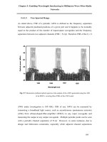
high mobility, wireless technologies will offer new alternatives. In Figure 5-1 the data rate
versus mobility for current and future standards (4G) is plotted. The current 2G GSM
system provides high mobility but a low data rate. 3G systems provide similar mobility as
Multi-Carrier and Spread Spectrum Systems K. Fazel and S. Kaiser
2003 John Wiley & Sons, Ltd ISBN: 0-470-84899-5
196 Applications
Tabl e 5- 1 Examples of average and peak data rates for different services
Service Average rate Peak rate
Video telephony and video conferencing 384 kbit/s to 2 Mbit/s 384 kbit/s to 2 Mbit/s
Video on demand (downlink only) 3 Mbit/s (typical) 6 Mbit/s
Computer gaming 10 kbit/s 25 Mbit/s
POTS 64 kbit/s 64 kbit/s
ISDN 144 kbit/s 144 kbit/s
Internet 10 kbit/s 25 Mbit/s
Remote LAN 10 kbit/s 25 Mbit/s
Compressed Voice 10 kbit/s 100 kbit/s
Mobility
Data rate
2G (e.g., GSM)
3G/3G
+
(UMTS/
IMT2000)
FWA-HIPERMAN/IEEE802.16a
DAB
HIPERLAN/2
IEEE802.11a
Beyond 3G,
4G
DVB-T
Figure 5-1 Data rate versus mobility in wireless standards
GSM but can deliver higher data rates as mobility decreases, i.e., up to 2 Mbps for pico
cells. The HIPERLAN/2 and IEEE 802.11a standards have been designed for high-rate
data services with low mobility and low coverage (indoor environments). On the other
hand, the HIPERMAN and IEEE 802.16a standards provide high data rates for fixed posi-
tioned wireless terminals with high coverage. HIPERLAN, IEEE 802.11a, HIPERMAN
and IEEE 802.16a can provide high peak data rates of up to 50 Mbit/s.
On the broadcast side, DAB offers similar mobility as GSM, however, with a much
higher broadcast data rate. Although the DVB-T standard was originally designed for
fixed or portable receivers, the results of several recent field trials have demonstrated its
robustness at high speeds as well [4].
Introduction 197
The common feature of the current wireless standards that offer a high data rate is the
use of multi-carrier transmission, i.e., OFDM [5][6][7][8][9][11][12]. In addition, these
standards employ adaptive technologies by using several transmission modes, i.e., allow-
ing different combinations of channel coding and modulation together with power control.
A simple adaptive strategy was introduced in DAB using multi-carrier differential QPSK
modulation (and also in GSM, using single-carrier GMSK modulation) with several punc-
tured convolutional code rates. By applying a simple combination of source and channel
coding, the primary goal was to protect the most important audio/speech message part
with the most robust FEC scheme and to transmit the less important source-coded data
even without FEC. This technique allows one to receive the highest quality sound/speech
in most reception conditions and an acceptable quality in the worst reception areas, where
it should be noted that in analog transmission no signal would be received.
DVB-T employs different concatenated FEC coding rates with high-order modulation
up to 64-QAM and different numbers of sub-carriers and guard times. Here the objective
is to provide different video quality versus distance and different cell-planning flexibility,
i.e., country-wide single frequency network or regional network, for instance, using so-
called taboo channels (free channels that cannot be used for analog transmission due to
the high level of co-channel interference).
In UMTS, besides using different FEC coding rates, a variable spreading factor (VSF)
with adaptive power control is introduced. As in GSM, the combination of FEC with
source coding is exploited. The variable spreading code allows a good trade-off between
coverage, single-cell/multi-cell environments, and mobility. For high coverage areas with
high delay spread, large spreading factors can be applied and for low coverage areas with
low delay spread, the smallest spreading factor can be used.
In HIPERLAN/2, IEEE 802.11a, and draft HIPERMAN and IEEE 802.16a standards,
a solution is adopted based on the combination of multi-carrier transmission with high
order modulation (up to 64-QAM), adaptive FEC (variable rate convolutional coding or
concatenated coding) and adaptive power control. For each user, according to its required
data rate and channel conditions the best combination of FEC, modulation scheme, and
the number of time slot is allocated. The main objective is to offer the best trade-off
between data rate and coverage, where the mobility is not of great importance. These
standards also allow different guard times adapted to different cell coverages.
Offering a trade-off between coverage, data rate, and mobility with a generic air inter-
face architecture is the primary goal of the next generation of wireless systems. Users
having no mobility and the lowest coverage distance (pico cells) with an ideal channel
condition will be able to receive the highest data rate, where on the other hand subscribers
with the highest mobility conditions and highest coverage area (macro-cells) will be able
to receive the necessary data rate to establish the required communication link. A combi-
nation of MC-CDMA with variable spreading codes or OFDM with adaptive technologies
(adaptive FEC, modulation, and power control) can be considered as potential candidates
for 4G.
The aim of this chapter is to examine in detail the different application fields of multi-
carrier transmission for multiuser environments. This chapter gives an overview of the
important technical parameters, and highlights the strategy behind their choices. First, a
concrete example of the application of MC-CDMA for a future 4G cellular mobile radio
system is given. Then, the OFDM-based HIPERLAN/2 and IEEE 802.11a standards are
198 Applications
studied. The application of OFDM and OFDMA in fixed wireless access is then examined.
Finally, the DVB-T return channel (DVB-RCT) specification is presented.
5.2 Cellular Mobile Communications Beyond 3G
5.2.1 Objectives
Besides the introduction of new technologies to cover the need for higher data rates and
new services, the integration of existing technologies in a common platform, as illustrated
in Figure 5-2, is an important objective of the next generation of wireless systems.
Hence, the design of a generic multiple access scheme for new wireless systems is
challenging. This new multiple access scheme should enable i) the integration of existing
technologies, ii) higher data rates in a given spectrum, i.e., maximizing the spectral effi-
ciency, iii) different cell configurations to be supported and automatic adaptation to the
channel conditions, iv) simple protocol and air interface layers, and finally, v) a seamless
adaptation of new standards and technologies in the future.
Especially for the downlink of a cellular mobile communications system, the need
for data rates exceeding 2 Mbit/s is commonly recognized. The study on high speed
downlink packet access (HSDPA) physical layer is currently under investigation within
the 3
rd
Generation Partnership Project (3GPP) [1]. To gain spectral efficiency, i.e., data
rate, the objective of HSDPA is to combine new techniques such as adaptive coding and
modulation, hybrid automatic repeat request (H-ARQ), and fast scheduling with the W-
CDMA air interface. However, even by adopting such techniques, a significant increase
in data rate cannot be expected, since the spectral efficiency of W-CDMA is limited by
multi-access interference (see Chapter 1).
Therefore, new physical layer and multiple access technologies are needed to provide
high-speed data rates with flexible bandwidth allocation. A low cost generic radio inter-
face, operational in mixed-cell and in different environments with scalable bandwidth and
data rate, is expected to have a better acceptance.
Fourth Generation
Platform
Broadband
Satellite
DVB-S
S-UMTS
Terrestrial
Broadcast
DVB-T
DAB
Broadband
Cellular Mobile
EDGE
UMTS/IMT2000
GPRS
GSM
Broadband
FWA
LMDS
HA/HM
MMDS
Broadband
WLAN
Bluetooth
HL2/802.11
IR
MBS
Figure 5-2 Beyond 3G: Integrated perspective
Cellular Mobile Communications Beyond 3G 199
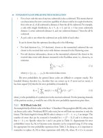
5.2.2 Network Topology and Basic Concept
An advanced 4G system with a point to multi-point topology for a cellular system based
on multi-carrier transmission has been proposed by NTT DoCoMo (see Figure 5-3) and
successful demonstrations have been carried out in the NTT DoCoMo testbed [2]. High-
rate multimedia applications with an asymmetrical data rate are the main objective. The
generic architecture allows a capacity optimization with seamless transition from a single
cell to a multi-cell environment. This broadband packet-based air interface applies variable
spreading factor orthogonal frequency and code division multiplexing (VSF-OFCDM)
with two-dimensional spreading in the downlink and MC-DS-CDMA for the uplink [2][3].
The target maximum throughput is over 100 Mbit/s in the downlink and 20 Mbit/s in the
uplink. The proposal mainly focuses on asymmetric FDD in order to avoid the necessity
of inter-cell synchronization in multi-cell environments and to accommodate independent
traffic assignment in the up- and downlink according to traffic.
An application of TDD for special environments is also foreseen. In both cases (FDD
and TDD) the same air interface is used.
Figure 5-4 illustrates the generic architecture proposed by NTT DoCoMo. The use of
a two-dimensional variable spreading code together with adaptive channel coding and
M-QAM modulation in an MC-CDMA system allows an automatic adaptation of the
radio link parameters to different traffic, channel, and cellular environment conditions.
Furthermore, by appropriate selection of the transmission parameters (FEC, constellation,
frame length, FFT size, RF duplex, i.e., TDD/FDD, etc.), this concept can support different
multi-carrier or spread spectrum-based transmission schemes. For instance, by choosing
a spreading factor of one in both the time and frequency direction, one may obtain a pure
OFDM transmission system. However, if the spreading factor in the frequency direction
and the number of sub-carriers are set to one, we can configure the system to a classical
DS-CDMA scheme. Hence, such a flexible architecture could be seen as a basic platform
for the integration of the existing technologies as well.
BS
TS
TS
TS
Cellular environment
Isolated single cell
Use of the same
air interface
with optimized
capacity
Broadband up-
and downlink
>> 2Mbps
Figure 5-3 Basic concept of NTT DoCoMo for 4G
200 Applications
FEC
(variable
rate)
M-QAM
Mapping
Two
dimen.
variable
spreading
Framing
Multi-
carrier
modulation
(OFDM)
D/A
IF/
RF
Radio link parameters adaptation
User 0
M-QAM
Mapping
Two
dimen.
variable
spreading
User
K − 1
FEC
(variable
rate)
.
.
.
Figure 5-4 Generic architecture concept of NTT DoCoMo
5.2.3 System Parameters
5.2.3.1 Downlink
As depicted in Figure 5-5, by using VSF-OFCDM for the downlink one can apply vari-
able spreading code lengths L and different spreading types. In multi-cell environments,
spreading codes of length L>1 are chosen in order to achieve a high link capacity by
using a frequency reuse factor of one. Two-dimensional spreading has a total spreading
Frequency
Time
Code
(Synchronized)
Time spreading, L
time
Frequency spreading, L
freq
#7
#6
#2
#5
#1
#4
#3
Multi-cell environment
Isolated single cell
Seamless
deployment
using the same
air interface
Two-dimensional
spreading
One-dimensional
spreading
Figure 5-5 Downlink transmission based on VSF-OFCDM
Cellular Mobile Communications Beyond 3G 201
code length of
L = L
time
L
freq
.(5.1)
Two-dimensional spreading with priority for time domain spreading rather than frequency
domain spreading is used. The motivation is that in frequency-selective fading channels
it is easier to maintain orthogonality among the spread user signals by spreading in the
time direction than in the frequency direction. The concept of two-dimensional spread-
ing is described in detail in Section 2.1.4.3. Additional frequency domain spreading in
combination with interleaving together with time domain spreading is used for channels
which have low SNR such that additional frequency diversity can enhance the transmis-
sion quality. The spreading code lengths L
time
and L
freq
are adapted to the radio link
conditions such as delay spread, Doppler spread, and inter-cell interference, and to the
link parameters such as symbol mapping. In isolated areas (hot-spots or indoor offices)
only one-dimensional spreading in the time direction is used in order to maintain orthog-
onality between the spread user signals. Finally, spreading can be completely switched
off with L = 1 if a single user operates in a isolated cell with a high data rate.
For channel estimation, two different frame formats have been defined. The first format
is based on a time multiplexed pilot structure where two subsequent OFDM symbols
with reference data are transmitted periodically over predefined distances. The second
format applies a code multiplexed pilot structure where the reference data is spread by
a reserved spreading code and multiplexed with the spread data symbols so that no
explicit pilot symbols or carriers are required. The assumption for this channel estimation
method is that the whole spreading code is faded flat and the different spreading codes
remain orthogonal.
Table 5-2 summarizes the downlink system parameters. Note that for signal detection at
the terminal station side, single-user detection with MMSE equalization is proposed before
despreading, which is a good compromise between receiver complexity and performance
achievement.
Furthermore, high-order modulation such as 16-QAM or 64-QAM is used with no
frequency or even time spreading. In a dense cellular system with high interference and
frequency selectivity the lowest order modulation QPSK with highest spreading factor in
both directions is employed.
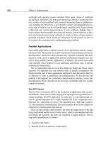
The throughput of a VSF-OFCDM system in the downlink is shown in Figure 5-6 [2].
The throughput in Mbit/s versus the SNR per symbol in a Rayleigh fading channel is
plotted. The system applies a spreading code length of L = 16, where 12 codes are used.
The symbol timing is synchronized using a guard interval correlation and the channel
estimation is realized with a time-multiplexed pilot channel within a frame. It can be
observed from Figure 5-6 that an average throughput over 100 Mbit/s can be achieved at
an SNR of about 13 dB when using QPSK with rate 1/2 Turbo coding.
5.2.3.2 Uplink
In contrast to the downlink, a very low number of sub-carriers in an asynchronous MC-
DS-CDMA has been chosen by NTT DoCoMo for the uplink. MC-DS-CDMA guarantees
a low-power mobile terminal since it has a lower PAPR reducing the back-off of the ampli-
fier compared to MC-CDMA or OFDM. A code-multiplexed pilot structure is applied for
channel estimation based on the principle described in the previous section. To combat the
202 Applications
Tabl e 5-2 NTT DoCoMo system parameters for the downlink
Parameters Characteristics/Values
Multiple access VSF-OFCDM
Bandwidth B 101.5 MHz
Data rate objective >100 Mbits/s
Spreading code Walsh–Hadamard codes
Spreading code length L 1–256
Number of sub-carriers N
c
768
Sub-carrier spacing F
s
131.8 kHz
OFDM symbol duration T
s
7.585 µs
Guard interval duration T
g
1.674 µs
Total OFDM symbol duration T
s
9.259 µs
Number of OFDM symbols per frame N
s
54
OFDM frame length T
fr
500 µs
Symbol mapping QPSK, 16-QAM, 64-QAM
Channel code Convolutional Turbo code, memory 4
Channel code rate R 1/3–3/4
0
50
100
150
200
−5
0 10152025
QPSK, R = 1/3
QPSK, R = 1/2
16QAM, R = 1/3
16QAM, R = 1/2
64QAM, R = 1/2
Average throughput (Mbps)
Average received E
s
/N
0
(dB)
Turbo coding (K = 4), SF = 16, 12 codes
without antenna diversity reception
12-path exponential decayed
Rayleigh fading (f
D
= 20 Hz)
5
Figure 5-6 Throughput with VSF-OFCDM in the downlink [2]
Wireless Local Area Networks 203
Frequency
Time
Code
(Asynchronous)
#7
#6
#2
#5
#1
#4
#3
Multi-cell environment
Isolated single cell
Seamless
deployment
using the same
air interface
user 1
user 2
Frequency
Time
Code
(Synchronized)
user 1 user 2 user 3
MC-DS-CDMA
FD-
MC-DS-CDMA
Figure 5-7 Uplink transmission based on MC-DS-CDMA and with an FD-MC-DS-CDMA option
multiple access interference, a rake receiver with interference cancellation in conjunction
with adaptive array antenna at the base station is proposed. As shown in Figure 5-7, the
capacity can be optimized for each cell configuration.
In a multi-cell environment, MC-DS-CDMA with complex interference cancellation at
the base station is used, where in a single-cell environment an orthogonal function in the
frequency (FD-MC-DS-CDMA) or time direction (TD-MC-DS-CDMA) is introduced into
DS-CDMA. In addition, this approach allows a seamless deployment from a multi-cell to
a single cell with the same air interface. The basic system parameters for the uplink are
summarizedinTable5-3.
Note that high-order modulation such as 16-QAM or 64-QAM is used even in a single
cell with no spreading and good reception conditions. However, in a dense cellular system
with high frequency selectivity and high interference, the lowest-order modulation QPSK
with the highest spreading factor is deployed.
In Figure 5-8, the throughput of an MC-DS-CDMA system in the uplink is shown [2].
The throughput in Mbit/s versus the SNR per symbol in a Rayleigh fading channel is
plotted. The system applies a spreading code length of L = 4, where 3 codes are used.
Receive antenna diversity with 2 antennas is exploited. The channel estimation is realized
with a code-multiplexed pilot channel within a frame. It can be observed from Figure 5-8
that an average throughput of over 20 Mbit/s can be achieved at an SNR of about 9 dB
when using QPSK with rate 1/2 Turbo coding.
5.3 Wireless Local Area Networks
Local area networks typically cover a story or building and their wireless realization
should avoid complex installation of a wired infrastructure. WLANs are used in public
204 Applications
Tabl e 5-3 NTT DoCoMo system parameters for the uplink
Parameters Characteristics/Values
Multiple access MC-DS-CDMA
Bandwidth B 40 MHz
Data rate objective >20 Mbit/s
Spreading code length L 1 – 256
Number of sub-carriers N
c
2
Sub-carrier spacing F
s
20 MHz
Chip rate per sub-carrier 16.384 Mcps
Roll-off factor 0.22
Total OFDM symbol duration T
s
9.259 µs
Number of chips per frame 8192
Frame length T
fr
500 µs
Symbol mapping QPSK, 16-QAM, 64-QAM
Channel code Convolutional Turbo code, memory 4
Channel code rate R 1/16–3/4
0
5
10
15
20
25
−8
−4 0 12 16
R = 1/3, 1 code
R = 1/3, 2 codes
R = 1/3, 3 codes
R = 1/2, 3 codes
Average throughput (Mbps)
Average received E
s
/N
0
per antenna (dB)
Turbo coding (K = 4), SF = 4, QPSK
2-branch antenna diversity reception
6-path exponential decayed
Rayleigh fading (f
D
= 20 Hz)
48
Figure 5-8 Throughput with MC-DS-CDMA in the uplink [2]
Wireless Local Area Networks 205
and private environments and support high data rates. They are less expensive than wired
networks for the same data rate, are simple and fast to install, offer flexibility and mobility,
and are cost-efficient due to the possibility of license exempt operation.
5.3.1 Network Topology
WLANs can be designed for infrastructure networks, ad hoc networks or combinations of
both. The mobile terminals in infrastructure networks communicate via the base stations
(BSs) which control the multiple access. The base stations are linked to each other by
a wireless (e.g., FWA) or wired backbone network. Infrastructure networks have access
to other networks, including the internet. The principle of an infrastructure network is
illustrated in Figure 5-9. Soft handover between different base stations can be supported
by WLANs such as HIPERLAN/2.
In ad hoc networks, the mobile terminals communicate directly with each other. These
networks are more flexible than infrastructure networks, but require a higher complexity
in the mobile terminals since they have to control the complete multiple access as base
station does. Communication within ad hoc networks is illustrated in Figure 5-10.
backbone network
BS
BS
BS
MT
MT
MTMTMT
Figure 5-9 WLAN as an infrastructure network
MT
MT
MT
Figure 5-10 WLAN as an ad hoc network
206 Applications
5.3.2 Channel Characteristics
WLAN systems often use the license-exempt 2.4 GHz and 5 GHz frequency bands which
have strict limitations on the maximum transmit power since these frequency bands are
also used by many other communications systems. This versatile use of the frequency band
results in different types of narrowband and wideband interference, such as a microwave
oven, which the WLAN system has to cope with.
WLAN cell size is up to several 100 m and multipath propagation typically results in
maximum delays of less than 1 µs. Mobility in WLAN cells is low and corresponds to a
walking speed of about 1 m/s. The low Doppler spread in the order of 10–20 Hz makes
OFDM very interesting for high-rate WLAN systems.
5.3.3 IEEE 802.11a, HIPERLAN/2, and MMAC
The physical layer of the OFDM-based WLAN standards IEEE 802.11a, HIPERLAN/2,
and MMAC are harmonized, which enables the use of the same chip set for products
of different standards. These WLAN systems operate in the 5 GHz frequency band. All
standards apply MC-TDMA for user separation within one channel and FDMA for cell
separation. Moreover, TDD is used as a duplex scheme for the separation of uplink
and downlink. The basic OFDM parameters of IEEE 802.11a and HIPERLAN/2 are
summarizedinTable5-4[8][11].
5.3.3.1 Frame structure
The TDD frame structure of HIPERLAN/2 is shown in Figure 5-11. One MAC frame
includes the header followed by the downlink (DL) phase, an optional direct link (DiL)
phase and the uplink (UL) phase. The MAC frame ends with a random access slot (RCH),
where users can request resources for the next MAC frame. The duration of the DL, DiL,
Tabl e 5- 4 OFDM parameters of IEEE 802.11a and HIPERLAN/2
Parameter Val ue
IFFT/FFT length 64
Sampling rate 20 MHz
Sub-carrier spacing 312.5 kHz (= 20 MHz/64)
Useful OFDM symbol duration 3.2 µs
Guard duration 0.8 µs
Total OFDM symbol duration 4.0 µs
Number of data sub-carriers 48
Number of pilot sub-carriers 4
Total number of sub-carriers 52
Wireless Local Area Networks 207
MAC frame
BCH FCH ACH
DL phase UL phase
DiL phase
RCHs
MAC frame MAC frame MAC frame
2 ms
Figure 5-11 TDD frame structure of HIPERLAN/2
time
frequency
−8,125 MHz
8,125 MHz
0
800 ns 4 µs
pilots
data
Figure 5-12 OFDM frame of HIPERLAN/2 and IEEE 802.11a
and UL phases depends on the resources requested by the users and can vary from frame
to frame. A MAC frame has a duration of 2 ms and consists of 500 OFDM symbols.
MC-TDMA is applied as a multiple access scheme within IEEE 802.11a and HIPER-
LAN/2, where within the DL and UL phase different time slots are allocated to different
users. Each time slot consists of several OFDM symbols.
The OFDM frame structure specified by HIPERLAN/2 and IEEE 802.11a is shown
in Figure 5-12. The frame of 2 ms duration starts with up to 10 short pilot symbols,
208 Applications
TS TS
BS
TSTS
TS TS
CC
User data
Signalling
CC = Central controller
Figure 5-13 Connection types supported by HIPERLAN/2
depending on the frame type. These pilot symbols are used for coarse frequency synchro-
nization, frame detection and automatic gain control (AGC). The following two OFDM
symbols contain pilots used for fine frequency synchronization and channel estimation.
The OFDM frame has four pilot sub-carriers, which are the sub-carriers −21, −7, 7
and 21. These pilot sub-carriers are used for compensation of frequency offsets. The
sub-carrier 0 is not used to avoid problems with DC offsets.
HIPERLAN/2 supports two connection types. The first is called centralized mode and
corresponds to the classical WLAN infrastructure network connection. The second is
called direct mode, i.e., peer-to-peer communication, and enables that two mobile terminals
communicate directly with each other; only the link control is handled by a so-called
central controller (CC). The principle of both connection types is shown in Figure 5-13.
5.3.3.2 FEC Coding and Modulation
The IEEE 802.11a, HIPERLAN/2, and MMAC standards support the modulation schemes
BPSK, QPSK, 16-QAM and 64-QAM, in combination with punctured convolutional codes
(CC) with rates in the range of 1/2 up to 3/4.
The different FEC and modulation combinations supported by IEEE 802.11a are shown
in Table 5-5. This flexibility offers a good trade-off between coverage and data rate.
5.3.4 Transmission Performance
5.3.4.1 Transmission Capacity
As shown in Table 5-6, the use of flexible channel coding and modulation in the IEEE
802.11a standard provides up to 8 physical modes (PHY modes), i.e., combinations of
FEC and modulation. The data rates that can be supported are in the range of 6 Mbit/s
up to 54 Mbit/s and depend on the coverage and channel conditions.
Note that the data rates supported by HIPERLAN/2 differ only slightly from those of
Table 5-6. The data rate 24 Mbit/s is replaced by 27 Mbit/s and the data rate of 48 Mbit/s
is not defined.
It should be emphasized that the overall data rate in a cellular system is limited by the
coverage distance and the amount of interference due to a dense frequency reuse. Indeed,
a global capacity optimization per cell (or per sector) can be achieved if the PHY mode
Wireless Local Area Networks 209
Tabl e 5-5 FEC and modulation parameters of IEEE 802.11a
Modulation Code rate R Coded bits per
sub-channel
Coded bits per
OFDM symbol
Data bits per
OFDM symbol
BPSK 1/2 1 48 24
BPSK 3/4 1 48 36
QPSK 1/2 2 96 48
QPSK 3/4 2 96 72
16-QAM 1/2 4 192 96
16-QAM 3/4 4 192 144
64-QAM 2/3 6 288 192
64-QAM 3/4 6 288 216
Tabl e 5-6 Data rates of IEEE 802.11a
PHY Mode Data rate (Mbit/s)
1 BPSK, CC1/2 6
2 BPSK, CC3/4 9
3 QPSK, CC1/2 12
4 QPSK, CC3/4 18
5 16-QAM, CC1/2 24
6 16-QAM, CC3/4 36
7 64-QAM, CC2/3 48
8 64-QAM, CC3/4 54
is adapted to each terminal station link condition individually. Results in [10] show that
compared to a single PHY mode, the areal spectral efficiency can be at least doubled if
adaptive PHY modes are employed.
5.3.4.2 Link Budget
The transmit power, depending on the coverage distance, is given by
P
T
x
= Path loss +P
Noise
− G
Antenna
+ Fade Margin + Rx
loss
+
C
N
,(5.2)
where
Path loss = 10 log
10
4πf
c
d
c
n
(5.3)
210 Applications
Tabl e 5- 7 Minimum receiver sensitivity thresholds
for HIPERLAN/2
Nominal bit rate [Mbit/s] Minimum sensitivity
6 −85 dBm
9 −83 dBm
12 −81 dBm
18 −79 dBm
27 −75 dBm
36 −73 dBm
54 −68 dBm
is the propagation path loss, d represents the distance between the transmitter and the
receiver, f
c
is the carrier frequency, and c is the speed of light. In case of WLANs, n
can be estimated to be in the order of 3 to 4.
P
Noise
= FN
Thermal
= FKTB (5.4)
is the noise power at the receiver input, where F is the receiver noise factor (about 6
dB), K is the Blotzman constant (K = 1.38 ·10
−23
J/K), T is the temperature in Kelvin,
and B is the total occupied Nyquist bandwidth. The noise power is expressed in dBm.
G
Antenna
is the sum of the transmit and receive antenna gains, expressed in dBi. In WLAN,
the terminal station antenna can be omni-directional with 0 dBi gain, but the base station
antenna may have a gain of about 14 dBi. FadeMargin is the margin needed to counteract
the fading and is about 5 to 10 dB. Rx
loss
is the margin for all implementation losses and
all additional uncertainties such as interference. This margin can be about 5 dB. C/N is
the carrier-to-noise power ratio (equivalent to E
s
/N
0
) for BER = 10
−6
. By considering
a transmission power of about 23 dBm and following the above parameters for an omni-
directional antenna, the maximum coverage for the robust PHY mode at 2.4 GHz carrier
frequency can be estimated to be about 300 m.
The minimum receiver sensitivity thresholds for HIPERLAN/2, depending on the PHY
mode, i.e., data rate for a BER of 10
−6
, are given in Table 5-7. The receiver sensitivity
threshold Rx
th
is defined by
Rx
th
= P
Noise
+
C
N
+ Rx
loss
.(5.5)
5.4 Fixed Wireless Access below 10 GHz
The aim of the fixed broadband wireless access (FWA) systems HIPERMAN and IEEE
802.16a is to provide wireless high speed services, e.g., IP to fixed positioned residential
customer premises and to small offices/home offices (SOHO) with a coverage area up to
20 km. To maintain reasonably low RF costs for the residential market as well as good
Fixed Wireless Access below 10 GHz 211
penetration of the radio signals, the FWA systems should typically use below 10 GHz
carrier frequencies, e.g., the MMDS band (2.5–2.7 GHz) in the USA or around the 5
GHz band in Europe and other countries.
Advantages of FWA include rapid deployment, high scalability, lower maintenance
and upgrade costs compared to cable. Nevertheless, the main goal of a future-proof FWA
system for the residential market has to be an increase in spectral efficiency, in coverage,
in flexibility for the system/network deployment, in simplification of the installation and,
above all, reliable communication even in non-line of sight (NLOS) conditions has to
be guaranteed. In a typical urban or suburban deployment scenario, at least 30% of the
subscribers have an NLOS connection to the base station. In addition, for most users
LOS is obtained through rooftop positioning of the antenna that requires very accurate
pointing, thereby making the installation both time- and skill-consuming. Therefore, a
system operating in NLOS conditions enabling self-installation will play an important
role in the success of FWA for the residential market.
In response to these trends under the ETSI-Broadband Radio Access Networks (BRAN)
project the HIPERMAN (HIgh PErfoRmance Metropolitan Area Networks, HM) and
under the IEEE 802.16 project the WirelessMan (Wireless Metropolitan Area Networks,
WMAN) specification are currently under standardization. Both standards will offer a
wide range of data services (especially IP) for residential (i.e., single- or multi-dwelling
household) customers and for small to medium-sized enterprises by adopting multi-carrier
transmission for radio frequencies (RF) below 10 GHz.
5.4.1 Network Topology
As shown in Figure 5-14, the FWA system will be deployed to connect user network
interfaces (UNIs) physically fixed in customer premises to a service node interface (SNI)
of a broadband core network (e.g., IP), i.e., for last mile connections. The base station
NT
RT
.
.
.
NT
.
.
NT
BST
.
.
BST
BSC
Core
Network, IP
IATM, PSTN,
ISDN,
UNI
Air
interface
SNI
Network
Termination
BS
Transceiver
BS
Controller
Interworking
Function
Base Station, BS
IWF
IWF
RT
IWF
TS
Terminal Station, TS
Radio
Termination
Interworking
Function
Figure 5-14 Simplified FWA reference model
212 Applications
typically manages communications of more than one carrier or sector. For each base
station sector one antenna or more is positioned to cover the deployment region. The
terminal station antenna can be directional or omni-directional. At the terminal station
side the network termination (NT) interface connects the terminal station with the local
user network (i.e., LAN).
The FWA network deployments will potentially cover large areas (i.e., cities, rural
areas) [9][12]. Due to the large capacity requirements of the network, a high amount of
spectrum with high transmission ranges (up to 20 km) is needed. For instance a typical
network may therefore consist of several cells each covering a part of the designated
deployment area. Each cell will operate in a point- to multi-point (PMP) or mesh manner.
Two duplex schemes can be used: i) frequency division duplex (FDD) and ii) time
division duplex (TDD). The channel size is between 1.5 to 28 MHz wide in both the
FDD and the TDD case. The downlink data stream transmitted to different terminal
stations is multiplexed in the time domain by MC-TDM (Time Division Multiplexing)
using OFDM or OFDMA transmission. In the uplink case, MC-TDMA (Time Division
Multiple Access) will be used with OFDM or OFDMA.
5.4.2 Channel Characteristics
Table 5-8 lists some target frequency bands below 10 GHz carrier frequency. The channel
bandwidths depend on the used carrier frequency as well. The use of these radio bands
provides a physical environment where, due to its wavelength characteristics, line of sight
(LOS) is not necessary but multipath may be significant (delay spread is similar to DVB-T
up to 0.2 ms). Doppler effects are negligible due to the fixed positioned terminals. Therefore,
multi-carrier transmission to combat the channel frequency selectivity (NLOS conditions)
is an excellent choice for FWA below 10 GHz, i.e., HIPERMAN and WirelessMan.
In order to maximize the capacity, i.e., the spectral efficiency, and coverage per cell/
sector, several advanced technologies will be adopted [9][12]: i) adaptive coding, ii) adap-
tive modulation, and iii) adaptive power control mechanisms.
5.4.3 Multi-Carrier Transmission Schemes
The draft physical layer of the these standards supports multi-carrier transmission modes.
The basic transmission mode is OFDM. Depending on the selected time/frequency
Tabl e 5- 8 Example of some target frequency bands for HIPERMAN and WirelessMan
Frequency bands (GHz) Allocated Channel Spacing Remarks
2.150–2.162
2.500–2.690
125 kHz to (n × 6) MHz USA CFR 47 part 21.901,
part 74.902 (MMDS)
3.400–4.200 1.75 to 30 MHz paired with
1.75 to 30 MHz (FDD)
CEPT/ERC Rec.12-08
E/ITU-R F.1488, Annex II
3.400–3.700 n × 25 MHz (single or paired)
(FDD or TDD)
ITU-R F.1488, Annex I,
Canada SRSP-303.4
5.470–5.725 n × 20 MHz CEPT/ERC Rec.70-03
Fixed Wireless Access below 10 GHz 213
parameters, the system can support TDMA as well as OFDMA. This flexibility ensures
that the system can be optimized for short bursty applications as well as more streaming
applications. The main advantage of using OFDMA with high numbers of sub-carriers
with the same data rate as the OFDM mode is to provide higher coverage, i.e., a longer
guard time.
In the pure OFDM mode, a total of 256 sub-carriers will be transmitted at once. The
downlink applies time division multiplexing (TDM) and the uplink uses time division
multiple access (TDMA). In the OFDMA mode, the channel bandwidth is divided into
2048 sub-carriers, where each user is assigned to a given group of sub-carriers. Therefore,
the number of sub-carriers varies from 256 to 2048.
As shown in Figure 5-15, there are several sub-carrier types:
— data sub-carriers,
— pilot sub-carriers (boosted and used for channel estimation purposes),
— null sub-carriers (used for guard bands and DC sub-carrier).
5.4.3.1 OFDM Mode
In Figure 5-16, the OFDM frame structure for the downlink (DL) and the uplink (UL)
in case of FDD is illustrated. The frame has a nominal duration between 2–5 ms. The
total frame length is an integer multiple of OFDM symbols, such that the actual frame
duration is nearest to the nominal frame duration.
Important parameters of the OFDM mode are summarized in Tables 5-9 and 5-10.
The downlink is a TDM transmission. Every downlink frame starts with a preamble. The
preamble is used for synchronization purposes. It is followed by a control channel zone
and downlink data bursts. Each burst uses different physical modes and each downlink
burst consists of an integer number of OFDM symbols.
The uplink is a TDMA transmission. Every uplink burst emanating from each termi-
nal is preceded by a preamble. Each uplink burst, independent of channel coding and
modulation, transmits an integer number of OFDM symbols as well.
Guard band
Guard band
Pilots
DC sub-carrier
Total bandwidth (between 1.5 to 28 MHz)
Data sub-carriers
Data sub-carriers
Figure 5-15 Example of sub-carrier allocation
214 Applications
Frame n − 1 Frame n Frame n + 1
Control
channel
DL burst
PHY #1
DL burst
PHY #m
DL Sub-frame
UL PHY transmission
from TS #k
UL Sub-frame
UL PHY transmission
from TS #n
UL PHY transmission
from TS #i
DL
preamble
UL burst
TS #i
UL
preamble
Figure 5-16 Downlink and uplink frame structure for FDD mode
Tabl e 5-9 OFDM mode parameters
Parameter Val ue
Number of DC sub-carriers 1
Number of guard sub-carriers, left/right 28/27
Number of used sub-carriers 200
Total number of sub-carriers 256
Number of fixed located pilot sub-carriers 8
Tabl e 5-10 OFDM parameters for ETSI channelization with 256
sub-carriers
Bandwidth (MHz) T
s
(µs) T
g
(µs)
1.75 128 4 8 16 32
3.5 64 2 4 8 16
7 32 1 2 4 8
14 16 1/2 1 2 4
28 8 1/4 1/2 1 2
Fixed Wireless Access below 10 GHz 215
The uplink preamble consists of 2 × 128 samples with guard time (= one OFDM
symbol). The downlink preamble is made up of two OFDM symbols: the first one carries
4 × 64 samples and the second one transmits 2 × 128 samples. These reference samples
have good correlation properties which eases the synchronization tasks. The power of the
uplink and downlink preambles is boosted by 3 dB compared to the data part.
5.4.3.2 OFDMA Mode
As described in Chapter 3, in OFDMA only a part of the sub-carriers may be used for
data transmission. A set of sub-carriers, called a sub-channel, will be assigned to each
user (see Figure 5-17). For both uplink and downlink the used sub-carriers are allocated
to pilot and data sub-carriers. However, there is a small difference between the uplink
and the downlink sub-carrier allocation. In the downlink, there is one set of common pilot
carriers spread over all the bandwidth, whereas in the uplink each sub-channel contains
its own pilot sub-carriers. This is since the downlink is broadcast to all terminal stations,
but in the uplink each sub-channel is transmitted from a different terminal station. The
goal of these pilot sub-carriers is to estimate the channel characteristics.
For OFDMA with FDD, the frame duration is an integer number of three OFDM
symbols, where the actual frame duration is nearest to the nominal frame duration between
2–5 ms.
In addition to the sub-channel dimension (set of sub-carriers), OFDMA uses the time
dimension for data transmission. An uplink or downlink burst in OFDMA has a two-
dimensional allocation: a transmit burst is mapped to a group of contiguous sub-channels
and to contiguous OFDM symbols. Each data packet is first segmented into blocks sized
to fit into one FEC block. Then, each FEC block spans one OFDMA sub-channel in the
sub-channel axis and three OFDM symbols in time axis. The FEC blocks are mapped such
that the lowest numbered FEC block occupies the lowest numbered sub-channel in the
lowest numbered OFDM symbol. The mapping is continued such that the OFDMA sub-
channel index is increased for each FEC block mapped. When the edge of the data region
is reached, the mapping will continue from the lowest numbered OFDMA sub-channel in
the next OFDM symbol (see Figure 5-18).
For the uplink transmission a number of sub-channels over a number of OFDM symbols
is assigned per terminal station. The number of OFDM symbols shall be equal to 1 +3N ,
Guard band Guard band
DC sub-carrier
Total bandwidth (between 1.5 to 28 MHz)
Sub-channel 1 Sub-channel 2 . . . Sub-channel K
Figure 5-17 Example of OFDMA frequency allocation for K users
216 Applications
n
n + 1
n + 2
n + 3
n + 11
n + 12
n + 13
n + 14
n + 15
n + 23
n + 24
n + 25
n + 26
n + 27
n + 35
3 OFDM symbols
OFDM symbol numbering (Time)
k − 1
k
k + 1 k + 2
:
.
.
.
0
1
2
3
31
Sub-channel numbering (Frequency)
Note: The number n, n + 1, in the boxes indicate indices of the FEC block.
.
.
.
.
.
.
Figure 5-18 Example of mapping of FEC blocks to OFDMA sub-channels and symbols
where N is a positive integer. In other words the smallest number of allocated sub-
channels per terminal station is one sub-channel for a duration of four OFDM symbols,
where the first OFDM symbol is a preamble.
The transmission of the downlink is performed on the sub-channels of the OFDM sym-
bol. The number of sub-channels needed for different coding and modulation is transmitted
in the downlink control channel.
OFDMA Downlink Sub-Carrier Allocation
As shown in Figure 5-19, for the downlink the pilots will have both fixed and variable
positions [12]. The variable pilot location structure is repeated every four symbols. The
allocated data sub-carriers are partitioned into groups of contiguous sub-carriers. The
number of groups is therefore equal to the number of sub-carriers per sub-channel.
In Table 5-11, the basic OFDMA downlink parameters are given.
OFDMA Uplink Sub-Carrier Allocation
The total number of sub-carriers used are first partitioned into sub-channels (see Figure
5-20). Within each sub-channel, there are 48 data sub-carriers, one fixed located pilot
sub-carrier and four variable located pilot sub-carriers. The fixed located pilot is always
at sub-carrier 26 within each sub-channel. The variable located pilot sub-carriers are
repeated every 13 symbols, whereas the fixed and the variable positioned pilots will
never coincide.
In Tables 5-12 and 5-13 the OFDMA uplink parameters and guard times are given,
respectively. Note that for OFDMA with 2048 sub-carriers the symbol duration and guard
times will be four times longer than with 256 sub-carriers.
5.4.3.3 FEC Coding and Modulation
The FEC consists of the concatenation of a Reed–Solomon (RS) outer code and a punc-
tured convolutional inner code. Block Turbo codes and convolutional Turbo codes can
also be used. Different modulation schemes with Gray mapping (QPSK, 16-QAM, and
64-QAM) are employed.