Satellite networking principles and protocols phần 3 pot
Bạn đang xem bản rút gọn của tài liệu. Xem và tải ngay bản đầy đủ của tài liệu tại đây (1.14 MB, 38 trang )
42 Satellite Networking: Principles and Protocols
1.14 Digital video broadcasting (DVB)
Digital video broadcasting (DVB) technology allows broadcasting of ‘data containers’, in
which all kinds of digital data can be transmitted. It simply delivers compressed images,
sound or data to the receiver within these ‘containers’. No restrictions exist as to the kind
of information in the data containers. The DVB ‘service information’ acts like a header to
the container, ensuring that the receiver knows what it needs to decode.
A key difference of the DVB approach compared to other data broadcasting systems is that
the different data elements within the container can carry independent timing information.
This allows, for example, audio information to be synchronised with video information in
the receiver, even if the video and audio information does not arrive at the receiver at exactly
the same time.
This facility is, of course, essential for the transmission of conventional television pro-
grammes. The DVB approach provides a good deal of flexibility. For example, a 38 Mbit/s
data container could hold eight standard definition television (SDTV) programmes, four
enhanced definition television (EDTV) programmes or one high definition television (HDTV)
programme, all with associated multi-channel audio and ancillary data services.
Alternatively, a mix of SDTV and EDTV programmes could be provided or even mul-
timedia data containing little or no video information. The content of the container can be
modified to reflect changes in the service offer over time (e.g. migration to a widescreen
presentation format).
At present, the majority of DVB satellite transmissions convey multiple SDTV pro-
grammes and associated audio and data. DVB is also useful for data broadcasting services
(e.g. access to the World Wide Web).
1.14.1 The DVB standards
Digital video broadcasting (DVB) is a term that is generally used to describe digital television
and data broadcasting services that comply with the DVB ‘standard’.
In fact, there is no single DVB standard, but rather a collection of standards, technical
recommendations and guidelines. These were developed by the Project on Digital Video
Broadcasting, usually referred to as the ‘DVB Project’.
The DVB Project was initiated in 1993 in liaison with the European Broadcasting Union
(EBU), the European Telecommunications Standards Institute (ETSI) and the European
Committee for Electrotechnical Standardisation (CENELEC). The DVB Project is a consor-
tium of some 300 member organisations. As opposed to traditional governmental agency
standards activities round the world, the DVB Project is market-driven and consequently
works on commercial terms, to tight deadlines and realistic requirements, always with an
eye toward promoting its technologies through achieving economies of scale. Though based
in Europe, the DVB Project is international, and its members are in 57 countries round the
globe. DVB specifications concern:
•
source coding of audio, data and video signals;
•
channel coding;
•
transmitting DVB signals over terrestrial and satellite communications paths;
•
scrambling and conditional access;
Introduction 43
•
the general aspects of digital broadcasting;
•
software platforms in user terminals;
•
user interfaces supporting access to DVB services;
•
the return channel, as from a user back to an information or programme source to support
interactive services.
The DVB specifications are interrelated with other recognised specifications. DVB source
coding of audio-visual information as well as multiplexing is based on the standards evolved
by the Moving Picture Experts Group (MPEG), a joint effort of the International Organ-
isation for Standards (ISO) and the International Electrotechnical Commission (IEC). The
principal advantage of MPEG compared to other audio and audio coding formats is that
the sophisticated compression techniques used make MPEG files far smaller for the same
quality. For instance, the first standard, MPEG1, was introduced in 1991 and supports 52:1
compression, while the more recent MPEG2 supports compression of up to 200:1.
The DVB Project is run on a voluntary basis and brings together experts from more than
300 companies and organisations, representing the interests of manufacturing industries,
broadcasters and services providers, network and satellite operators and regulatory bodies.
Its main intent is to reap the benefits of technical standardisation, while at the same time
satisfying the commercial requirements of the project members. Although a large part of the
standardisation work is now complete, work is still ongoing on issues such as the Multimedia
Home Platform. Much of the output of the DVB Project has been formalised by ETSI.
1.14.2 DVB-S satellite delivery
One of the earliest standards developed by the DVB Project and formulated by ETSI was
for digital video broadcasting via satellite (usually referred to as the ‘DVB-S standard’).
Specifications also exist for the retransmission of DVB signals via cable networks and
satellite master antenna television (SMATV) distribution networks.
The techniques used for DVB via satellite are classical in the sense that they have been
used for many years to provide point-to-point and point-to-multipoint satellite data links in
‘professional’ applications. The key contribution of the DVB Project in this respect has been
the development of highly integrated and low-cost chip sets that adapt the DVB baseband
signal to the satellite channel. Data transmissions via satellite are very robust, offering a
maximum bit error rate in the order of 10
−11
.
In satellite applications, the maximum data rate for a data container is typically about
38 Mbit/s. This container can be accommodated in a single 33 MHz satellite transponder.
It provides sufficient capacity to deliver, for example, four to eight standard television
programmes, 150 radio channels, 550 ISDN channels, or any combination of these services.
This represents a significant improvement over conventional analogue satellite transmission,
where the same transponder is typically used to accommodate a single television programme
with far less operational flexibility.
A single modern high-power broadcasting satellite typically provides at least twenty
33 MHz transponders, allowing delivery of about 760 Mbit/s of data to large numbers of
users equipped with small (around 60 cm) satellite dishes.
A simple generic model of a digital satellite transmission channel comprises several basic
building blocks, which include baseband processing and channel adaptation in the transmitter
44 Satellite Networking: Principles and Protocols
and the complementary functions in the receiver. Central to the model is, of course, the
satellite transmission channel. Channel adaptation would most likely be done at the transmit
satellite earth station, while the baseband processing would be performed at a point close to
the programme source.
1.14.3 MPEG-2 baseband processing
MPEG is a group of experts drawn from industry who contribute to the development of
common standards through an ITU-T and ISO/IEC joint committee. The established MPEG-
2 standard was adopted in DVB for the source coding of audio and video information and
for multiplexing a number of source data streams and ancillary information into a single data
stream suitable for transmission. Therefore, many of the parameters, fields and syntax used
in DVB baseband processing are specified in the relevant MPEG-2 standards. The MPEG-2
standards are generic and very wide in scope. Some of the parameters and fields of MPEG-2
are not used in DVB.
The processing function deals with a number of programme sources. Each programme
source comprises any mixture of raw data and uncompressed video and audio, where the
data can be, for example, teletext and/or subtitling information and graphical information
such as logos.
Each of the video, audio and programme-related data is called an elementary stream (ES).
It is encoded and formatted into a packetised elementary stream (PES). Thus each PES is a
digitally encoded component of a programme.
The simplest type of service is a radio programme, which would consist of a single
audio elementary stream. A traditional television broadcast would comprise three elementary
streams: one carrying coded video, one carrying coded stereo audio and one carrying teletext.
1.14.4 Transport stream (TS)
Following packetisation, the various elementary streams of a programme are multiplexed
with packetised elementary streams from other programmes to form a transport stream (TS).
Each of the packetised elementary streams can carry timing information, or ‘time stamps’,
to ensure that related elementary streams, for example, video and audio, are replayed in
synchronism in the decoder. Programmes can each have a different reference clock, or
can share a common clock. Samples of each ‘programme clock’, called programme clock
references (PCRs), are inserted into the transport stream to enable the decoder to synchronise
its clock to that in the multiplexer. Once synchronised, the decoder can correctly interpret
the time stamps and can determine the appropriate time to decode and present the associated
information to the user.
Additional data is inserted into the transport stream, which includes programme specific
information (PSI), service information (SI), conditional access (CA) data and private data.
Private data is a data stream whose content is not specified by MPEG.
The transport stream is a single data stream that is suitable for transmission or storage. It
may be of fixed or variable data rate and may contain fixed or variable data rate elementary
streams. There is no form of error protection within the multiplex. Error protection is
implemented within the satellite channel adaptor.
Introduction 45
1.14.5 Service objectives
The DVB-S system is designed to provide so-called ‘quasi error free’ (QEF) quality. This
means less than one uncorrected error event per transmission hour, corresponding to a bit
error rate (BER) of between 10
−10
and 10
−11
at the input of the MPEG-2 demultiplexer (i.e.
after all error correction decoding). This quality is necessary to ensure that the MPEG-2
decoders can reliably reconstruct the video and audio information.
This quality target translates to a minimum carrier-to-noise ratio C/N requirement for
the satellite link, which in turn determines the requirements for the transmit earth station
and the user’s satellite reception equipment for a given satellite broadcasting network. The
requirement is actually expressed in E
b
/N
0
(energy per bit to noise density ratio), rather than
C/N , so that it is independent of the transmission rate.
The DVB-S standard specifies the E
b
/N
0
values at which QEF quality must be achieved
when the output of the modulator is directly connected to the input of the demodulator (i.e.
in an ‘IF loop’). An allowance is made for practical implementation of the modulator and
demodulator functions and for the small degradation introduced by the satellite channel.
The values range from 4.5 dB for rate 1/2 convolutional coding to 6.4 dB for rate 7/8
convolutional coding.
The inner code rate can be varied to increase or decrease the degree of error protection for
the satellite link at the expense of capacity. The reduction or increase in capacity associated
with a change in the code rate and the related increase or reduction in the E
b
/N
0
requirement.
The latter is also expressed as an equivalent increase or reduction in the diameter of
the receive antenna (the size of user’s satellite dish), all other link parameters remaining
unchanged.
1.14.6 Satellite channel adaptation
The DVB-S standard is intended for direct-to-home (DTH) services to consumer integrated
receiver decoders (IRD), as well as for reception via collective antenna systems (satellite
master antenna television (SMATV)) and at cable television head-end stations. It can support
the use of different satellite transponder bandwidths, although a bandwidth of 33 MHz
is commonly used. All service components (‘programmes’) are time division multiplexed
(TDM) into a single MPEG-2 transport stream, which is then transmitted on a single digital
carrier.
The modulation is classical quadrature phase shift keying (QPSK). A concatenated error
protection strategy is employed based on a convolutional ‘inner’ code and a shortened Reed–
Solomon (RS) ‘outer’ code. Flexibility is provided so that transmission capacity can be
traded off against increased error protection by varying the rate of the convolutional code.
Satellite links can therefore be made more robust, at the expense of reduced throughput per
satellite transponder (i.e. fewer DVB services).
The standard specifies the characteristics of the digitally modulated signal to ensure
compatibility between equipment developed by different manufacturers. The processing
at the receiver is, to a certain extent, left open to allow manufacturers to develop their
own proprietary solutions. It also defines service quality targets and identifies the global
performance requirements and features of the system that are necessary to meet these targets.
46 Satellite Networking: Principles and Protocols
1.14.7 DVB return channel over satellite (DVB-RCS)
The principal elements of a DVB return channel over satellite (DVB-RCS) system are the hub
station and user satellite terminals. The hub station controls the terminals over the forward
(also called outbound link), and the terminals share the return (also called inbound link). The
hub station continuously transmits the forward link in time division multiplex (TDM). The
terminals transmit as needed, sharing the return channel resources using multi-frequency time
division multiple access (MF-TDMA). The DVB-RCS system supports communications on
channels in two directions:
•
Forward channel, from the hub station to many terminals.
•
Return channels, from the terminals to the hub station.
The forward channel is said to provide ‘point-to-multipoint’ service, because it is sent by
a station at a single point to stations at many different points. It is identical to a DVB-S
broadcast channel and has a single carrier, which may take up the entire bandwidth of a
transponder (bandwidth-limited) or use the available transponder power (power limited).
Communications to the terminals share the channel by using different slots in the TDM
carrier.
The terminals share the return channel capacity of one or more satellite transponders
by transmitting in bursts, using MF-TDMA. In a system, this means that there is a set
of return channel carrier frequencies, each of which is divided into time slots which can
be assigned to terminals, which permits many terminals to transmit simultaneously to the
hub. The return channel can serve many purposes and consequently offers choices of some
channel parameters. A terminal can change frequency, bit rate, FEC rate, burst length, or
all of these parameters, from burst to burst. Slots in the return channel are dynamically
allocated.
The uplink and downlink transmission times between the hub and the satellite are very
nearly fixed. However, the terminals are at different points, so the signal transit times
between them and the satellite vary. On the forward channel, this variation is unimportant.
Just as satellite TV sets successfully receive signals whenever they arrive, the terminals
receive downlink signals without regard to small differences in their times of arrival.
However, on the uplink, in the return direction from the terminals to the hub, small
differences in transit time can disrupt transmission. This is because the terminals transmit
in bursts that share a common return channel by being spaced from each other in time. For
instance, a burst from one terminal might be late because it takes longer to reach the satellite
than a burst sent by another terminal. A burst that is earlier or later than it should be can
collide with the bursts sent by the terminals using the neighbouring TDMA slots.
The difference in transmission times to terminals throughout the footprint of a satellite
might be compensated for by using time slots that are considerably longer than the bursts
transmitted by the terminals, so both before and after a burst there is a guard time sufficiently
long to prevent collisions with the bursts in neighbouring slots in the TDMA frame. The
one-way delay time between a hub and a terminal varies from 250 to 290 ms, depending on
the geographical location of the terminal with respect to the hub. So the time differential,
T, might be as large as 40 ms. So most TDMA satellite systems minimise guard time by
incorporating various means of timing adjustment to compensate for satellite path differences.
Introduction 47
DVB-RCS has two built-in methods of pre-compensating the burst transmission time of each
terminal:
•
Each terminal ‘knows’ its local GPS coordinates and therefore can calculate its own burst
transmission time.
•
The hub monitors the arrival times of bursts, and can send correction data to terminals if
need be.
1.14.8 TCP/IP over DVB
DVB-RCS uses the MPEG-2 digital wrappers, in which ‘protocol-independent’ client traffic
is enclosed within the payloads of a stream of 188-byte packets. The MPEG-2 digital wrapper
offers a 182-byte payload and has a 6-byte header. The sequence for transmission of Internet
TCP/IP traffic includes:
•
The TCP/IP message arrives and is subjected to TCP optimisation.
•
The IP packets are divided into smaller pieces and put into data sections with 96-bit digital
storage medium – command and control (DSM-CC) headers.
•
The DSM-CC data sections are further divided into 188-byte MPEG2-TS packets in the
baseband processing.
•
The MPEG2-TS packets then are subjected to channel coding for satellite transmissions.
1.15 Historical development of computer and data networks
Telecommunication systems and broadcasting systems have been developing for over 100
years. The basic principles and services have changed little since their beginnings and we
can still recognise the earliest telephony systems and televisions. However, computers and
the Internet have changed greatly in the last 40 years. Today’s systems and terminals are
completely different from those used 40 or even 10 years ago. The following gives a quick
review of these developments to show the pace of technology progress.
1.15.1 The dawn of the computer and data communications age
The first electronic digital computer was developed during 1943–6. Early computer interfaces
used punched tapes and cards. Later terminals were developed and the first communication
between terminals and computer over long distances was in 1950, which used voice-grade
telephone links at low transmission speeds of 300 to 1200 kbit/s. Automatic repeat requests
(ARQ) for error correction were mainly used for data transmission.
1.15.2 Development of local area networks (LANs)
From 1950 to 1970 research carried out on computer networks led to the development of
different types of network technologies – local area networks (LANs), metropolitan area
networks (MANs) and wide area networks (WANs).
48 Satellite Networking: Principles and Protocols
A collection of standards, known as IEEE 802, was developed in the 1980s including
the Ethernet as IEEE802.3, token bus as IEEE802.4, token ring as IEEE802.5, DQDB as
IEEE802.6 and others. The initial aim was to share file systems and expensive peripheral
devices such as high-quality printers and graphical plot machines at fast data rates.
1.15.3 Development of WANs and ISO/OSI
The ISO developed the Open System Interconnection (OSI) reference model with seven
layers for use in wide area networks in the 1980s. The goal of the reference model was to
provide an open standard so that different terminals and computer systems could be connected
together if they conformed to the standard. The terminals considered in the reference model
were connected to a mainframe computer over a WAN in text mode and at slow speed.
1.15.4 The birth of the Internet
Many different network technologies were developed during the 1970s and 1980s and many
of them did not fully conform to international standards. Internetworking between different
types of networks used protocol translators and interworking units, and became more and
more complicated as the protocol translators and interworking units became more technology
dependent.
In the 1970s, the Advanced Research Project Agency Network (ARPARNET) sponsored
by the US Department of Defense developed a new protocol, which was independent of
network technologies, to interconnect different types of networks. The ARPARNET was
renamed as the Internet in 1985. The main application layer protocols included remote telnet
for terminal access, FTP for file transfer and email for sending mail through computer
networks.
1.15.5 Integration of telephony and data networks
In the 1970s, the ITU-T started to develop standards called integrated services digital net-
works with end-to-end digital connectivity to support a wide range of services, including
voice and non-voice services. User access to the ISDN was through a limited set of standard
multipurpose customer interfaces. Before ISDN, access networks, also called local loops,
to the telecommunication networks were analogue, although the trunk networks, also called
transit networks, were digital. This was the first attempt to integrate telephony and data
networks and integration of services over a single type of network. It still followed the
fundamental concepts of channel- and circuit-based networks used in traditional telecommu-
nication networks.
1.15.6 Development of broadband integrated networks
As soon as the ISDN was completed in the 1980s, the ITU-T started to develop broadband
ISDN. In addition to broadband integrated services, ATM technology was developed to
support the services based on fast packet-switching technologies. New concepts of virtual
Introduction 49
channels and circuits were developed. The network is connection oriented, which allows
negotiation of bandwidth resources and applications. It was expected to unify the telephony
networks and data networks and also unify LANs, MANs and WANs.
From the LAN aspect, ATM faced fierce competition from fast Ethernet. From application
aspects, it faced competition from the Internet.
1.15.7 The killer application WWW and Internet evolutions
In 1990, Tim Berners-Lee developed a new application called the World Wide Web (WWW)
based on hypertext over the Internet. This significantly changed the direction of network
research and development. A large number of issues needed to be addressed to cope with the
requirements of new services and applications, including real-time services and their quality
of service (QoS), which were not considered in traditional Internet applications.
1.16 Historical development of satellite communications
Satellite has been associated with telecommunications and television from its beginning, but
few people have noticed this. Today, satellites broadcast television programmes directly to
our homes and allow us to transmit messages and surf the Internet. The following gives a
quick review of satellite history.
1.16.1 Start of satellite and space eras
Satellite technology has advanced significantly since the launch of the first artificial satellite
Sputnik by the USSR on 4 October 1957 and the first experiment of an active relaying
communications satellite Courier-1B by the USA in August 1960.
The first international cooperation to explore satellite for television and multiplexed tele-
phony services was marked by the experimental pre-operation transatlantic communications
between the USA, France, Germany and the UK in 1962.
1.16.2 Early satellite communications: TV and telephony
Establishment of the Intelsat organisation started with 19 national administration and initial
signatories in August 1964. The launch of the REARLY BIRD (Intelsat-1) marked the first
commercial geostationary communication satellite. It provided 240 telephone circuits and
one TV channel between the USA, France, Germany and the UK in April 1965. In 1967,
Intelsat-II satellites provided the same service over the Atlantic and Pacific Ocean regions.
From 1968 to 1970, Intelsat-III achieved worldwide operation with 1500 telephone circuits
and four TV channels. The first Intelsat-IV satellite provided 4000 telephone circuits and
two TV channels in January 1971 and Intelsat-IVa provided 20 transponders of 6000 circuits
and two TV channels, which used beam separation for frequency reuse.
50 Satellite Networking: Principles and Protocols
1.16.3 Development of satellite digital transmission
In 1981, the first Intelsat-V satellite achieved capacity of 12 000 circuits with FDMA and
TDMA operations, 6/4 GHz and 14/11 GHz wideband transponders, and frequency reuse by
beam separation and dual polarisation. In 1989, the Intelsat-VI satellite provided onboard
satellite-switched TDMA of up to 120 000 circuits. In 1998, Intelsat VII, VIIa and Intelsat-
VIII satellites were launched. In 2000, the Intelsat-IX satellite achieved 160 000 circuits.
1.16.4 Development of direct-to-home (DTH) broadcast
In 1999, the first K-TV satellite provided 30 14/11-12 GHz transponders for 210 TV pro-
grammes with possible direct-to-home (DTH) broadcast and VSAT services.
1.16.5 Development of satellite maritime communications
In June 1979, the International Maritime Satellite (Inmarsat) organisation was established to
provide global maritime satellite communication with 26 initial signatories. It explored the
mobility feature of satellite communications.
1.16.6 Satellite communications in regions and countries
At a regional level, the European Telecommunication Satellite (Eutelsat) organisation was
established with 17 administrations as initial signatories in June 1977. Many countries also
developed their own domestic satellite communications systems, including the USA, the
USSR, Canada, France, Germany, the UK, Japan, China and other nations.
1.16.7 Satellite broadband networks and mobile networks
Since the 1990s, significant development had been carried out on broadband networks
including onboard-switching satellite technologies. Various non-geostationary satellites have
been developed for mobile satellite services (MSSs) and broadband fixed satellite services
(FSSs).
1.16.8 Internet over satellite networks
Since the late 1990s and the start of the twenty-first century, we have seen a dramatic
increase in Internet traffic over the communication networks. Satellite networks have been
used to transport Internet traffic in addition to telephony and television traffic for access
and transit networks. This brings great opportunities as well as challenges to the satellite
industry. On one hand, it needs to develop internetworking with many different types of
legacy networks; and on the other hand, it needs to develop new technologies to internetwork
with future networks. We have also see the convergence of different types of networks
including network technologies, network protocols and new services and applications.
Introduction 51
1.17 Convergence of network technologies and protocols
The convergence is the natural progression of technologies pushing and user demands pulling
and the development of business cases. Obviously, satellite networking closely follows the
development of terrestrial networks, but is capable of overcoming geographical barriers and
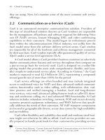
the difficulty of wide coverage faced by terrestrial networks. Figure 1.27 illustrates the vision
of a future satellite network in the context of the global information infrastructure.
1.17.1 Convergence of services and applications in user terminals
In the early days, user terminals were designed for particular types of services and had very
limited functions. For example, we had telephone handsets for voice services, computer
terminals for data services, and television for receiving television services. Different networks
were developed to support these different types of terminals.
As the technology developed, additional terminals and services were introduced into the
existing networks. For example, fax and computer dialup services were added to telephone
networks. However, the transmission speeds of fax and dialup links were limited by the
capacity of the telephone channel supported by the telephony networks.
Computer terminals have become more and more sophisticated and are now capable of
dealing with voice and video services in real time. Naturally, in addition to data services,
there are increasing demands to support real time voice and video over data networks.
Multimedia services, a combination of voice, video and data, were developed. These
complicate the QoS requirements requiring complicated user terminal and network design,
implementation and operation.
To support such services over satellite networks for applications such as aeronautics,
shipping, transport and emergency services brings even more challenges. We are starting to
see the convergence of different user terminals for different types of services into a single
user terminal for all types of services.
Satellite
Urban
In-Building
Pico-cell
Global
Suburban
Home-cell
Macro-cell
dik
In-Home
Micro-cell
Figure 1.27 Satellite in the global information infrastructure
52 Satellite Networking: Principles and Protocols
1.17.2 Convergence of network technologies
Obviously, network services are closely related to the physical networks. To support a new
generation of services we need a new generation of networks. However, the design of new
services and networks needs significant amounts of investment and a long period of time
for research and development. To get users to accept new services and applications is also
a great challenge.
How about building new services on the existing networking infrastructure? Yes, this
approach has been tried as far as possible, as mentioned previously, fax and computer dialup
were added to telephony networks, and voice and video services to data networks. This
approach does not ease the task of developing new services and networks, as the original
designs of the networks were optimised for original services. Therefore, new networks have
to be developed for new services and applications.
Luckily we do not need to start from scratch. The telephone networks and services on the
existing networks have been developing over the past 100 years; during that time we have
accumulated a huge amount of knowledge and experience.
1.17.3 Convergence of network protocols
Following the concepts of telecommunication networking principles, attempts were made to
develop new services and networks. Examples of these are the integrated services digital
networks (ISDN), synchronous transfer mode (STM) networks, broadband ISDN (B-ISDN)
and asynchronous transfer mode (ATM) networks. As telephony services are historically
the major services in the telecommunication networks, the new networks are biased towards
these services, and are perhaps emphasising too much on real time and QoS. The results are
not completely satisfactory.
Computer and data networks have been developing for about 50 years, during this time
we have also accumulated a significant amount of knowledge and experience in the design
of computers and data networks. All the computer and data network technologies have
converged to the Internet technologies. In LAN, Ethernet is the dominating technology; other
LANs, such as token ring and token bus networks are disappearing. Of course, wireless
LANs are becoming popular. The Internet protocols are now the protocol for computer and
data networking. One of the most important successful factors is backward compatibility,
i.e., new network technology should be capable of supporting the existing services and
applications and internetworking with the existing user terminals and network without any
modifications.
Following the success of the Internet, significant research and development have been
carried out to support telephony services and other real-time services. As the original design
of the Internet was for data services, it was optimised for reliable data services without much
thought given to real-time services and QoS. Therefore, IP telephony cannot be achieved
easily with the level of QoS provided by telecommunication networks.
Convergence of network design is inevitable, however, we have to learn from the telecom-
munication networks for QoS and reliable transmission of data from the Internet.
The principles of networking are still the same: to improve reliability; increase capacity;
support integrated services and applications; to reach anywhere and anytime; and particularly
important for satellite networking to fully utilise limited resources and reduce costs.
Introduction 53
1.17.4 Satellite network evolution
It can be seen that satellite communication started from telephony and TV broadcast terrestrial
networks. It went on to increase capacity, extend coverage to the oceans for mobile service,
and extend services to data and multimedia services.
Satellites have become more sophisticated, and have progressed from single transpar-
ent satellites to onboard processing and onboard switching satellites, and further to non-
geostationary satellite constellations with inter-satellite links (ISL).
Basic satellites have a repeater to relay signals from one side to the other. Satellites with
this type of payload are called transparent satellites. They also called pent-pipe satellites as
they simply provide links between terminals without processing.
Some satellites have onboard processing (OBP) as part of the communication subsystems
to provide error detection and error correction to improve the quality of the communication
links, and some have onboard switching (OBS) to form a network node in the sky to explore
efficient use of radio resources. Experiments have also been also carried out to fly IP router
onboard satellites due to the recent rapid development of Internet.
Satellites have played an important role in telecommunications networks supporting tele-
phony, video, broadcast, data, broadband and Internet services and have become an important
integrated part of the global information infrastructure providing the next generation of
integrated broadband and Internet network.
Further reading
[1] Brady, M. and M. Rogers, Digital Video Broadcasting Return Channel via Satellite (DVB-RCS) Background
Book, Nera Broadband Satellite AS (NBS), 2002.
[2] Eutelsat, Overview of DVB, Annex B to Technical Guide, June 1999.
[3] Haykin, S., Communication Systems, 4th edition, John Wiley & Sons, Inc., 2001.
[4] ITU, Handbook on Satellite Communications, 3rd edition, John Wiley & Sons, Inc., 2002.
[5] Joel, A., Retrospective: telecommunications and the IEEE communications society, IEEE Communications,
May 2002.
[6] Khader, M. and W.E. Barnes, Telecommunications Systems and Technology, Prentice-Hall, 2000.
Exercises
1. Explain the meaning of broadband, using the definition given in the ITU-T recom-
mendations.
2. Explain the basic concepts of satellite networking and internetworking with terres-
trial networks.
3. Explain the terms satellite services, network services and quality of service (QoS).
4. Discuss the differences between satellite networking and terrestrial networking
issues.
5. Explain the functions of network user terminals and satellite terminals.
6. Derive the Shannon power limit and the Shannon bandwidth capacity for large
E
b
/N
0
.
7. Explain the basic principles of protocols and the ISO reference model.
54 Satellite Networking: Principles and Protocols
Exercises (continued)
8. Explain the basic ATM reference model.
9. Explain the Internet protocol TCP/IP suite.
10. Explain the basic concepts of multiplexing and multiple accessing.
11. Explain the basic switching concepts including circuit switching, virtual circuit
switching and routeing.
12. Explain the evolution process and convergence of network technologies and
protocols.
2
Satellite Orbits and Networking
Concepts
This chapter aims to provide an introduction to the physical layer of satellite networking
concepts including principles of satellite orbits, satellite link characteristics, transmission
techniques, multiple access, bandwidth allocation, and satellite availability and diversity.
The physical layer is the lowest layer of network protocol stacks, providing real signal
transmission. In the context of the protocol reference model, it provides service to the
link layer above, however, there are no layers below it. It is the layer directly related to
transmission media technologies and performs many of the functions of radio communication
systems. In this chapter we will focus on satellite networking related issues. When you have
completed this chapter, you should be able to:
•
Review the laws of physics including Kepler’s laws and Newton’s laws.
•
Make use of the laws to explain the characteristics of satellite orbits and calculate satellite
orbit parameters.
•
Make use of the laws to design orbits for a single satellite or a constellation of satellites
for different requirements of satellite networking coverage.
•
Appreciate thecharacteristics of satellite links and calculate the values ofthe linkparameters.
•
Understand different types of modulation techniques and why the phase shift modulation
technique is more suitable for satellite transmission.
•
Know the important error correcting coding schemes.
•
Know different bandwidth resource allocation schemes and their applications.
•
Describe the satellite networking design issues.
•
Understand the concept of quality of service (QoS) at the physical layer.
•
Know the quality of a satellite system in terms of availability and the techniques to
improve satellite availability.
Satellite Networking: Principles and Protocols Zhili Sun
© 2005 John Wiley & Sons, Ltd
56 Satellite Networking: Principles and Protocols
2.1 Laws of physics
Like terrestrial mobile base stations, satellite communications systems have to be installed
on a platform or bus. The laws of physics determine how and where we can put the base
station in the sky to form an integrated part of our network.
2.1.1 Kepler’s three laws
The German astronomer Johannes Kepler (1571–1630) formulated three laws of planetary
motion that also apply to the motion of satellites around earth. Kepler’s three laws are:
1. The orbit of any smaller body about a large body is always an ellipse, with the centre of
mass of the large body as one of the two foci.
2. The orbit of the smaller body sweeps out equal areas in equal time.
3. The square of the period of revolution of the smaller body about a large body equals
a constant multiplied by the third power of the semi major axis of the orbital ellipse.
2.1.2 Newton’s three laws of motion and the universal law of gravity
In 1687, the British astronomer, mathematician, physicist and scientist Issac Newton discov-
ered the three laws of motion as the following:
1. A body stays motionless, or continues moving in a straight line, unless a force acts on it.
2. Any change in movement of a body is always proportional to the force that acts on it, and
is made in the direction of the straight line in which the force acts. It can be described
mathematically as the sum of all vector forces
F
acting on a body with a mass of m
equals the product of the mass and acceleration of vector
r
of the body:
F
= m
d
2
r
dt
2
(2.1)
3. Every action has an opposite and equal reaction. In addition to the three laws, Newton
also discovered the force of gravity (the force that made the apple fall to the ground).
More importantly, he provided a mathematical proof of the force of gravity forming the
universal law of gravity as the ‘two-body problem’:
F
= Gm
1
m
2
1
r
2
r
r
(2.2)
where
F
is the vector force of mass m
1
on the mass m
2
in the direction from m
1
to
m
2
G=6672×10
−11
m
3
/kg/s
2
is the universal gravity constant, r is the distance between
the two bodies, and
r
r
is the unit vector showing the direction from m
1
to m
2
. Clearly this
can be used to describe the force between the sun and earth by letting m
1
be the mass of the
sun and m
2
be the mass of the earth.
Satellite Orbits and Networking Concepts 57
2.1.3 Kepler’s first law: satellite orbits
Newton derived Kepler’s laws mathematically. Mathematics is the most important tool in
systems design and analysis. Here, we should make use of our analytical skills to look into
the fundamental and theoretical aspects of satellite orbits. By taking the following steps, we
can approve Kepler’s first law for the satellite case mathematically.
First, apply Newton’s third law to get:
F
= GMm
1
r
2
r
r
= m
1
r
2
r
r
(2.3)
where the mass of the earth M = 5974 ×10
24
kg, Kepler’s constant = GM = 3986 ×
10
14
m
3
/s
2
, and satellite mass is m kg.
Second, applying Newton’s second law of motion, force = mass × acceleration, we get:
d
2
r
dt
2
+
r
r
3
= 0 (2.4)
Then, referring to Figure 2.1 and letting
x
=
r
/r and
y
is the unit vector orthogonal to
x
, we get:
d
r
dt
=
dr
dt
x
t +r
d
dt
y
t (2.5)
d
2
r
dt
2
=
d
2
r
dt
2
−r
d
dt
2
x
t +
r
d
2
dt
2
+2
dr
dt
d
dt
y
t (2.6)
Substituting Equation (2.6) into Equation (2.4) gives:
d
2
r
dt
2
−r
d
dt
2
+
u
r
2
x
t +
r
d
2
dt
2
+2
dr
dt
d
dt
y
t = 0 (2.7)
∆θ
r(t+∆t)
៝
θ
r(t)
៝
r(t)
៝
∆r(t)
៝
(a) (b)
∆r(t) = ∆rx + r∆θy
៝៝
x
៝
∆x(t)=∆θy
៝
∆r(t)
៝
៝
y
៝
∆y(t) = –∆θx
៝៝
y
៝
៝
∆θ
θ
r(t
+ ∆t)
៝
θ
Figure 2.1 Vector from earth to satellite
58 Satellite Networking: Principles and Protocols
Hence:
d
2
r
dt
2
−r
d
dt
2
+
r
2
= 0 (2.8)
r
d
2
dt
2
+2
dr
dt
d
dt
= 0 (2.9)
From Equation (2.9), we get:
1
r
d
dt
r
2
d
dt
= 0;
Hence
r
2
d
dt
= DConstant (2.10)
Let u = 1/r in Equation (2.10), we get
d
dt
= Du
2
(2.11)
Hence:
dr
dt
=
dr
d
d
dt
=
−
1
u
2
du
d
d
dt
=−D
du
d
(2.12)
d
2
r
dt
2
=
dr
dt
dr
dt
=
du
d
d
dt
dr
dt
=−D
2
u
2
d
2
u
d
2
(2.13)
Substituting Equations (2.11) and (2.13) into Equation (2.8) gives:
d
2
u
d
2
+u =
D
2
(2.14)
Letting
p =
D
2
(2.15)
and solving the second-order liner differential equation (2.14) gives the following:
u =
1
p
+A cos −
0
Hence:
r =
p
1 +pAcos −
0
(2.16)
where A and
0
are constants, and adjustment can be made so that
0
= 0.
Satellite Orbits and Networking Concepts 59
Therefore, we can represent Kepler’s first law mathematically for satellite orbits as the
following equation illustrated in Figure 2.2:
r
=
p
1 +ecos
(2.17)
where e = pA.
Note that the earth is at one of the foci. Point A is the nearest point to earth, called perigee;
and point B is the furthest point, called apogee. The radius of earth is R
E
= 6378 km. The
relationships between the parameters are listed as the following:
r
min
= h
A
+R
E
= a1 −e = p/1 +e (2.18)
r
max
= h
B
+R
E
= a1 +e = p/1 −e (2.19)
a = r
min
+r
max
/2 = h
A
+h
B
/2 +R
E
= p/1 −e
2
(2.20)
b =a
2
−c
2
1/2
= a1 −e
2
1/2
= r
min
r
max
1/2
= p/1 −e
2
1/2
(2.21)
p = b
2
/a (2.22)
c = ae = r
max
−r
min
/2 = h
B
−h
A
/2 = ep/1 −e
2
(2.23)
e = c/a = r
max
−r
min
/r
max
+r
min
= h
B
−h
A
/h
B
+h
A
+2R
E
(2.24)
p = a1 −e
2
= 2r
max
r
min
/r
max
+r
min
(2.25)
2.1.4 Kepler’s second law: area swept by a satellite vector
From Equations (2.10) and (2.15), we can get the following equation:
1
2
r
2
d
dt
=
D
2
=
1
2
√
p Constant (2.26)
This agrees with Kepler’s second law.
Apogee
Perigee
a
b
c
r
r
max
r
min
a
b
θ
ea
r
A
B
F
F’
O
h
B
h
A
satellite
Figure 2.2 Orbit with major axis of orbit (AB) and semi-major axis of orbit (AO)
60 Satellite Networking: Principles and Protocols
2.1.5 Kepler’s third law: orbit period
Integrating from 0 to T, the period of the orbit, we get that the left-hand side of Equation 2.26
equals the area of the ellipse and the equation becomes:
ab =
T
0
1
2
√
p dt =
T
2
√
p (2.27)
Hence using Equation (2.22), we can rewrite Equation (2.27) into
T =
2ab
√
p
=
2
a
3
2
(2.28)
This agrees with Kepler’s third law.
According to period T of a satellite completing the orbit, satellite orbits can be classified
as the following types:
•
Geostationary orbit, if T = 24 hours and i = 0. The orbit has the same period a sidereal
day. To be more precise, a sidereal day equals 23 h 56 min 4.1 s, which totals 86 154 s.
It can be calculated that the semi-major axis a = 42164 km and the satellite velocity
v = 3075 m/s.
•
Geosynchronous orbit, if T = 24 hours and 0 <i<90
.
•
Non-geosynchronous orbit, if T = 24 hours. More satellites have to be used to form a
constellation with a number of orbit planes and a few satellites arranged in each plane for
continuous service to a coverage area.
2.1.6 Satellite velocity
Substituting Equations (2.10), (2.13) and (2.15) into Equation (2.8) gives
d
2
r
dt
2
−
p
r
3
2
+
r
2
= 0
Then making use of Equation (2.25) and integrating both sides of the above equation gives:
1
2
dr
dt
2
+
a1 −e
2
2r
2
−
r
=
0dr = EConstant (2.29)
At perigee, there are boundary values r = r
min
= a1 −e and
dr
dt
= 0. Substituting into
Equation (2.29) gives:
E =
a1 −e
2
2a
2
1 −e
2
−
a1 −e
=−
2a
(2.30)
Satellite Orbits and Networking Concepts 61
Using Equations (2.5), (2.25), (2.26) and (2.29), the satellite velocity can be calculated as:
2
=
d
r
dt
2
=
dr
dt
2
+
r
d
dt
2
=
dr
dt
2
+
a1 −e
2
r
2
=2E +
2
r
=
2
r
−
1
a
(2.31)
It can be seen from Equations (2.17), (2.18) and (2.19) that v reaches a maximum at
perigee where
r
= r
min
= a1 −e, and a minimum at apogee when
r
= r
max
= a1 +e,
and the speed can be calculated as:
min
=
1 −e
a1 +e
(2.32)
max
=
1 +e
a1 −e
(2.33)
2.2 Satellite orbit parameters
In order to define the trajectory of a satellite in space, orbital parameters are required.
The shape of an orbit is described by two parameters: the semi-major axis ( a) and the
eccentricity (e). The position of the orbital plane in space is specified by means of other
parameters: the inclination (i), the right ascension of the node () and argument of perigee
(). The semi-major axis (a) also determines the period (T) of a satellite orbiting earth.
2.2.1 Semi-major axis (a)
This element specifies the size of the orbit (in km). It is defined as one-half of the major
axis, which is the length of the chord that passes through the two foci of the orbit’s ellipse.
For circular orbits, the semi-major axis ( a) is simply the radius of the circle. Figure 2.2
illustrates the semi-major axis and other the orbit parameters.
2.2.2 Eccentricity (e)
Eccentricity (e) determines the shape of the orbit. It is a unitless geometric constant with a
value between zero and one. A pure circular orbit has an eccentricity of zero. The following
values of e define the types of the satellite orbits:
•
For e = 0, the trajectory is a circle.
•
For e<1, the trajectory is an ellipse.
•
For e = 1, the trajectory is a parabola.
•
For e>1, the trajectory is a hyperbola.
62 Satellite Networking: Principles and Protocols
2.2.3 Inclination of orbit (i)
The inclination (i) determines the tilt of the orbital plane with respect to the equatorial plane
of the earth and is an angle measured in degrees. It is defined as the angle between the two
planes shown in Figure 2.3. An orbit with an inclination of zero degrees is called an equatorial
orbit; an orbit with an inclination of 90 degrees is called a polar orbit. Inclinations of less
than 90 degrees correspond to direct orbits (i.e., the satellite is rotating around the North
Pole heading east) and inclinations between 90 and 180 degrees correspond to retrograde
orbits (i.e., the satellite is rotating around the North Pole heading west). Inclinations are
limited to a maximum of 180 degrees.
According to the inclination angle i of the orbital plane, the angle between the earth’s
equatorial plane and the satellite’s orbital plane, satellite orbits, as shown in Figure 2.4 can
be classified as the following types:
•
Equatorial orbit, if i = 0. The orbital is on the same plane as the earth equator.
•
Incline orbit, if 0 <i<90
. The orbital plane and earth equator plane have an angle of i
degrees.
•
Polar orbit, if i = 90
. The orbital plane contains the earth pole.
(a) Orbit plane on the equator plane (i
=
0)
•
•
•
•
i
(b) Inclination of the orbit plane i (0
< i <
90°)
Ascending node
•
•
•
•
•
Figure 2.3 Inclination of orbit i
Equatorial orbi
t
Incline orbit
Polar orbit
Figure 2.4 Equatorial, incline and polar orbits
Satellite Orbits and Networking Concepts 63
Ω
(a) Right ascension of the node Ω (0 ≤ Ω ≤ 360°)
(b) Argument of perigee ω (0
≤ ω ≤ 360°)
•
•
•
•
•
•
i
Ω
i
•
ω
•
•
•
•
•
••
••
Figure 2.5 Right Ascension of the node and argument of perigee
2.2.4 Right ascension of the node () and argument of perigee ()
Right ascension of the node () determines the rotation of the orbital plane, and is an
angle measured in degrees. It is defined as the angle in the equatorial plane between the
lines formed by the intersection of the orbital planes and the equatorial plane as shown in
Figure 2.5(a). Thus, this ‘longitude’ is not a normal longitude tied to the earth’s surface, but
is an angle measured in the equatorial plane. It is therefore also called right ascension of the
ascending node (RAAN). Argument of perigee () determines the rotation of perigee on the
orbital plane as shown in Figure 2.5(b), and is an angle measured in degrees.
2.3 Useful orbits
According to Kepler’s third law, the orbital period of a satellite is proportional to its distance
from earth. Satellites in low orbits, altitudes of a few hundred to a thousand km, have orbital
periods less than two hours; in contrast, the moon, at an altitude of about 380 000 km, has
an orbital period of about 27 days, which is the base of the lunar month of the Chinese
calendar; and earth has a orbit period of about 365 days as the base of a year.
2.3.1 Geosynchronous earth orbits
Between the extremes is an altitude that corresponds to an orbital period of one day.
A satellite in a circular orbit at such an altitude revolves around earth at the same speed
as earth’s rotation. This altitude is 35,786.6 km, and the orbit is called a synchronous or
geosynchronous orbit.
If the orbital plane of a satellite is not coincident with earth’s equatorial plane, then
the orbit is said to be inclined, and the angle between the orbital plane and the equatorial
plane is known as the orbit’s inclination. In a geosynchronous orbit, the point on the earth
directly below the satellite moves north and south in a narrow figure-eight pattern as shown
in Figure 2.6 with northern and southern latitude limits corresponding to the inclination.
A constellation of geosynchronous satellites is needed to provide continuous coverage of
an area.
64 Satellite Networking: Principles and Protocols
(a)
geosynchronous orbit
geostationary orbit
(b)
(d)(c)
Satellite
Satellite
Figure 2.6 Footprints of geosynchronous satellites
2.3.2 Geostationary earth orbits (GEOs)
If inclination of a geosynchronous orbit is zero (or near zero), the satellite remains fixed
(or approximately fixed) over one point on the equator. Such an orbit is known as a geosta-
tionary orbit.
An advantage of the geostationary orbit is that antennas on the ground, once aimed at
the satellite, need not continue to rotate. Another advantage is that a satellite in this type of
orbit continuously sees about one-third of earth.
At an altitude of 35 786.6 km above the equator, the angular velocity of a satellite in this
orbit matches the daily rotation of the earth’s surface, and this orbit has been widely used
as a result. Propagation delay between earth station and satellite is around 0.125 ms; this
leads to the widely quoted half-second round-trip latency quoted for communications via
geostationary satellite.
One disadvantage of the geostationary orbit is that the gravity of the sun and moon disturb
the orbit, causing the inclination to increase. The satellite’s propulsion can counter this
disturbance, but since the amount of fuel a satellite can carry is limited, increased inclination
may remain a problem in some scenarios. The geostationary orbit’s finite capacity is another
disadvantage; satellites using the same frequencies must be separated to prevent mutual
interference. Providing coverage of high latitudes (above 75
) is generally not possible, so
full earth coverage cannot be achieved with a geostationary constellation.
2.3.3 High elliptical orbits (HEOs)
High elliptical orbits (HEOs) differ from the circular orbits. They provide coverage only
when the satellite is moving very slowly relative to the ground while at apogee, furthest
from the earth’s surface, and power requirements in link budgets are dimensioned for this
distance. Figure 2.7 illustrates a typical elliptical orbit.
These orbits are generally at an inclination of 63.4 degrees so that the orbit is quasi-
stationary with respect to the earth’s surface. This high inclination enables coverage of high
Satellite Orbits and Networking Concepts 65
(a)
Elliptical orbit
geostationary orbit
(b)
Satellite moving at
fastest speed at this
point.
Satellite moving
slowest speed at this
point.
Figure 2.7 A typical high elliptical orbit
latitudes, and Russian use of Molnya and Tundra elliptical orbits for satellite television to
the high-latitude Russian states is well known.
As elliptical orbits are the exception rather than the general rule, and generally provide
targeted selection, rather than general worldwide coverage, we will not consider them
further here.
2.3.4 Notations of low earth orbit (LEO) satellite constellations
LEO satellites move faster than the rotation of earth. Therefore, they appear to continuously
circulate around the earth. Figure 2.8 illustrates the orbit and footprint of an LEO satellite.
A constellation of satellites is needed to provide global coverage.
Satellite orbit plane and the point on the orbit can allocate a satellite position. For a
constellation of satellites, there are simple notations or rules to describe it for a global
coverage. There are two forms of notations used to describe satellite constellations in the
literature – Walker notation and Ballard notation:
•
Walker notation (N/P/p): this notation refers to: (number of satellites per plane/number
of planes/number of distinct phases of planes to control spacing offsets in planes).
•
Ballard notation ( NP, P, m): this notation refers to: (total number of satellites NP, number
of planes P, harmonic factor m describing phasing between planes).
(a)
Low earth orbit
geostationary orbit
(b)
Satellite
Satellite
Figure 2.8 Footprint of a LEO satellite
66 Satellite Networking: Principles and Protocols
The Walker notation is more commonly seen, although the Ballard notation can more
accurately describe possible offsets between planes.
2.3.5 Orbital perturbations
There are many subtle effects that perturb earth satellite orbits, invalidating the simple orbits
predicted by two-body gravity equations. Some of the factors that perturb the orbit are:
•
Earth’s oblateness: the earth bulges at the equator, which leads to a much more complex
gravity field than the spherically symmetric field of a ‘point’ gravity source.
•
Solar and lunar effects: these effects of the sun and moon are the most influential gravi-
tational forces on earth satellites besides the earth’s own field.
•
Atmospheric drag: the friction that a satellite encounters as it passes through the diffuse
upper layers of the earth’s atmosphere.
•
Solar radiation pressure: solar radiation pressure is caused by collisions between the
satellite and photons radiating from the sun, which are absorbed or reflected.
2.3.6 Satellite altitude and coverage
The higher the altitude, the longer the distance one is able to see. The longer the distance, the
higher the transmission power is required for communications. Figure 2.9 illustrates these
simple relationships.
It can be seen that the GEO satellite has the highest altitude covering the largest area, the
LEO satellite has the lowest altitude covering the smallest area and the MEO is in between.
The GEO satellite also provides a fixed and continuous coverage of the area, but the LEO
and MEO satellites will gradually move away from the coverage areas. These imply that the
LEO and MEO satellites provide advantages for small and lower terminals at the cost of
complicated constellations of satellite systems. Such complications also incur the high cost
of deployment and operation of the constellations.
Satellites
Figure 2.9 Relationships between altitude and coverage