Wideband tdd wcdma for the unpaired spectrum phần 4 pot
Bạn đang xem bản rút gọn của tài liệu. Xem và tải ngay bản đầy đủ của tài liệu tại đây (385.23 KB, 29 trang )
Layer 1 Structure 53
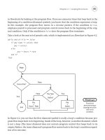
Table 4.3 Code Groups and Cell Parameters
Code Group Cell
Parameter
Associated Codes
Scrambling
Code
Long Basic
Midamble Code
Short Basic
Midamble Code
0 Code 0 mPL0 mSL0
1 Code 1 mPL1 mSL1
Group 0 2 Code 2 mPL2 mSL2
3 Code 3 mPL3 mSL3
4 Code 4 mPL4 mSL4
Group 1 5 Code 5 mPL5 mSL5
6 Code 6 mPL6 mSL6
7 Code 7 mPL7 mSL7
UEs will use the PRACH/P for UL communication with UTRAN when they do not have
a dedicated channelization code assigned, such as during initial access to UTRAN. This
results in the possibility of collision (i.e. multiple UEs using the same PRACH/P at the
same time). For this reason, a set of admissible channelization codes on the PRACH/P is
specified, from which the UE randomly selects a code. The random selection is used to
minimize the possibility of collision. The midamble is determined through a fixed associ-
ation between the midamble and the channelization code [7]. The available midambles for
PRACH/P are from the long midamble set, using either all eight shifts or only the four odd
shifts from k = 1 to 8. Using odd-only shifts is intended for larger cells; whereby using
only half of the available midamble shifts allows for double-length channel responses.
For larger cells, the effective number of available midamble shifts can be doubled from
four to eight by using a second basic midamble sequence, which is a time ‘inverted’ or
reverse version of the original basic midamble sequence.
Since Random Access is used for initial access to UTRAN, the UE does not have tight
time synchronization with the UTRAN. For this reason, PRACH/P uses Type-3 bursts,
which have the larger guard period of 192 chips. This reduces the probability of the
PRACH/P transmission spilling into an adjacent timeslot. Power Control is not used on
the PRACH/P channel.
Each PRACH/P can be split into N-subchannels, with the i-th subchannel using the
frames with i = SFN mod N, with possible values of N being 1, 2, 4 or 8. The purpose
of the subchannels is to reduce probability of collision, by offering more opportunities
for random transmissions.
Multiple PRACH/Ps may be configured on the same or different timeslots. If they
are on different timeslots, then each PRACH/P may use the channelization codes and
subchannels without any restrictions. However, if they are on the same timeslot, then
each PRACH/P must use distinct subsets of channelization codes and sub-channels. From
a service point of view, the Random Access Channel is partitioned into a number of Access
Service Classes (ASCs), each having a relative priority level. For example, high priority
ASCs are assigned for Emergency Calls as well as for Network Operator personnel, etc.
Each ASC is mapped onto one or more PRACH/P subchannels and a set of associated
channelization codes.
54 TDD Radio Interface
The details of the PRACH/PC (Timeslot, channelization code list, midamble type, sub-
channels, ASCs, etc.) are transmitted by the UTRAN on the broadcast channel. Physical
Uplink and Downlink Shared Channels: PUSCH/P and PDSCH/P. As the name indicates,
Physical Uplink and Downlink Shared Channels are common channels on which several
users may send and receive data.
Higher layer signaling is used to indicate to the UE that there is data to decode on
the shared channels. PDSCH/P and PUSCH/P use the same burst structure of PDCH/P as
described in Section 4.3.1.2.
4.3.1.7 Physical Paging Indicator Channel: PICH/P
The Physical Paging Indicator Channel (PICH/P) is a physical channel used to carry the
paging indicators. The PICH/P is always transmitted at a power level that is broadcast in
system information (specified as an offset from the PCCPCH/P reference power level).
A Paging Indicator is a sequence of L
PI
symbols, which indicates to a UE whether or
not Paging Information is present in the following occurrence of the Paging (transport)
channel (PCH/T). L
PI
is either 2, 4 or 8 symbols. A single Paging Indicator is assigned
to a group of the UEs based on IMSIs (International Mobile Subscriber Identity). This
increases the system’s paging capacity but will sometimes cause UEs to decode the PCH/T
when they have not been paged.
Bursts of Type-1 or Type-2 are used to carry Paging Indicators. With a spreading factor
of 16 and with 4 bits being reserved, the number of bits available for Paging Indicators
(NPIB) is 240 for Type-1 and 272 for Type-2 bursts, see Figure 4.8.
Accordingly, the number of Paging Indicators per Burst, N
PI
, is easily determined to
be as shown in Table 4.4.
A number of PICH Bursts (N
PICH
), with one burst per timeslot per frame, form a PICH
Block, as shown in Figure 4.9.
Thus, the total number of Paging Indicators per PICH Block N
P
is N
PICH
∗
N
PI
.
Bits for Paging Indication Reserved Bits Bits for Paging Indication
b
0
b
1
b
NPIB/2−1
b
NPIB/2
b
NPIB/2+1
b
NPIB+2
b
NPIB−1
b
NPIB+3
b
NPIB+1
b
NPIB
Midamble
Guard
Period
1 Timeslot
Figure 4.8 Paging Indicators in a PICH Burst
Table 4.4 Number of Paging Indicators per Burst
L
PI
= 2L
PI
= 4L
PI
= 8
Burst Type 1 N
PI
= 60 N
PI
= 30 N
PI
= 15
Burst Type 2 N
PI
= 68 N
PI
= 34 N
PI
= 17
Layer 1 Structure 55
1 PICH Block
P
0, ,
P
NPI−1
P
0, ,
P
NPI−1
P
0, ,
P
NPI−1
P
0, ,
P
NPI−1
Frame #n 0 1 N
PICH
-2 N
PICH
-1
Figure 4.9 Structure of a PICH/P Block
PICH data does not use the channel coding, rate matching or interleaving used by other
transport channel types. PICH data is in effect repetition-coded (L
PI
times) and interleaved
between the first and second data fields.
4.3.2 Transport Channels
As explained in Section 4.1, Transport Channels are the services that the Physical Layer
provides to Layer 2. Transport Channels are characterized by how data is transferred, in
terms of the size of the data block, the periodicity of the data blocks, the type of error
protection, etc. A Transport Channel is a very flexible concept that allows a variety of
channels with very different characteristics to be realized.
The definition of a Transport Channel is based on the concepts of Transmission Time
Interval and Transport Format as follows. Briefly, a Transport Channel consists of a
sequence of time periods, called Transmission Time Intervals (TTIs). Data in a TTI
consists of one or more ‘Transport Blocks’, carrying equal number of bits. The data
is characterized by a ‘Transport Format (TF)’, which specifies the number of Transport
Blocks, the number of data bits per Transport Block and the duration of the TTI itself.
The Transport Format also specifies other parameters, as described below.
The TTI can be either 10, 20, 40 or 80 msecs. The number of TBs in a TTI can
be 0 through 512, with 0 TBs denoting that no data is transported within that TTI.
The maximum number of bits in a TB is 5000. Additional so-called semi-static TB
attributes are:
1. Coding Scheme (Convolutional Rate 1/2 or Convolutional Rate 1/3 or Turbo or
No-coding).
2. Number of CRC bits (0, 8, 12, 16, 24).
3. Rate Matching parameter (integer from 1 to 256). The Rate Matching parameter puts
limits on the number of error-coded bits that may be punctured (or deleted) in the
process of mapping the data from multiple transport channels onto a CCTrCH. If
the RM parameter is higher for one TrCH than for another, the one with the higher
RM parameter would be given more of the output bits and, therefore less puncturing
would be performed on that TrCH. If there is only one TrCH in the CCTrCH, the RM
parameter has no effect.
TB size (bits), number of TBs and TTI, which effectively determine the Layer 2 to Layer
1 data rate, can be ‘changed’ on a TTI basis. That is, the following so-called ‘dynamic’
56 TDD Radio Interface
attributes can have multiple values, one of which is selected or in effect for any particular
TTI: (1) transport block size; (2) number of transport blocks per TTI; and (3) TTI. These
parameters are changed by the MAC, which performs TFC selection, based on a number
of factors such as data available from each logical channel and logical channel priority.
The other TrCH parameters are referred to as semi-static parameters. TTI can be either
a dynamic or a semi-static parameter. These parameters require higher layer signaling. All
the attributes characterizing a TrCH can be changed on a slow basis by reconfiguration.
The set of possible TFs for a Transport Channel is called a Transport Format Set (TFS)
and each TF within the TFS is known by a unique Transport Format Indicator (TFI).
Example: TFS ={TF1, TF2, TF3}
TF1: Dynamic part: {TB size = 320 bits, No. of TBs = 1};
Semi-static part: {TTI = 10 ms, Coding = Convolutional,
Coding Rate = 1/2; Static rate matching parameter = 2}.
TF2: Dynamic part: {TB size = 320 bits, No. of TBs = 2};
Semi-static part: {TTI = 10 ms, Coding = Convolutional, Coding Rate = 1/2;
Static rate matching parameter = 2}.
TF3: Dynamic part: {TB size = 480 bits, No. of TBs = 3};
Semi-static part: {TTI = 10 ms, Coding = Convolutional, Coding Rate = 1/2;
Static rate matching parameter = 2}.
Specific Realization in time: (TF1, TF3, TF2) is shown in Figure 4.10.
Coded Composite Transport Channel (CCTrCH): Multiple Transport Channels with
different error protection requirements (which are driven by the Quality of Service require-
ments) can be multiplexed to form a Coded Composite Transport Channel (CCTrCH).
This can save physical resources by sharing them among multiple transport channels. The
parameters of the individual TrCHs (number of bits after error coding + rate matching)
must be such that their mapping onto the allocated Physical Channels is possible.
The structure of the Coded Composite Transport Channels is based on the concept of
Transport Format Combination (TFC), which is introduced via an example. For example,
consider 3 Transport Channels (TrCH1, TrCH2 and TrCh3) being combined to form a
single CCTrCH. Let the associated Transport Format Sets be TFS1 ={TF1, TF2}, TFS2 =
{TF1} and TFS3 ={TF1, TF2, TF3}, where TF1, TF2 and TF3 are as defined in the
previous example. A ‘Transport Format Combination’ refers to allowed combinations
of Transport Formats for the three channels. For example, TFC1 ={TrCH1 =
TrCH
Transmission Time Interval
Transport Block
Transport Block
Transport Block
Transport Block
Transport Block
Transport Block
Figure 4.10 Example of a Transport Channel
Layer 1 Structure 57
TF1, TrCH2 = TF1, TrCH3 = TF1},TFC2={TrCH1 = TF2, TrCH2 = TF1, TrCH3 =
TF2} and TFC3 ={TrCH1 = TF1, TrCH2 = TF1, TrCH3 = TF3}. Note that the number
of allowed TFCs (3) is smaller than the total number of theoretical TF combinations (6).
The CCTrCH is now defined by a set of allowed TFCs, i.e. CCTrCH: TFCS ={TFC1,
TFC2, TFC3}. An example realization in time is shown in Figure 4.11.
The Transport Format Combination present in a specific radio frame is denoted by a
group of bits TFC Indicator (TFCI), first introduced in Section 3.2.1. This is a key field of
data for the receiver, as it indicates what Transport Blocks to look for in the radio frame.
4.3.2.1 Transport Channel Types
TDD radio interface defines a number of Transport Channels, which may be classified
into two groups:
• Common Transport channels (where the transport channel is common to several UEs,
which may be explicitly addressed for data transfer to a particular UE).
• Dedicated Transport channels (where the transport channel, i.e. TFCS, Coding, TTI,
etc., is dedicated to a particular UE).
TrCH3
Transmission Time Interval
Transport Block
Transport Block
Transport Block
Transport Block
TrCH2
Transmission Time Interval
Transport Block
TF1
TrCH1
Transmission Time Interval
Transport Block
Transport Block
Transport Block
TF1
TF2
TF1
Transport Block
Transport Block
TF1
Transport Block
Transport Block
TF2
TF1
Transport Block
TF1
TF3
TFC1
TFC3
TFC2
CCTrCH
Figure 4.11 Example of a CCTrCH
58 TDD Radio Interface
There are six types of Common Transport channel types in TDD – RACH/T, FACH/
T, DSCH/T, USCH/T, BCH/T, PCH/T:
• The Random Access Channel (RACH/T) is a contention-based uplink channel used
for transmission of signaling messages and relatively small amounts of data, e.g. for
initial access or non-real-time dedicated control or traffic data. The TTI for RACH/T
channel is fixed at 10 msecs, whereas the Transport Block size, Transport Block Set
size, CRC size and rate-matching parameters are not fixed by the standards. However,
a CCCH message must be sent in a single RACH burst (Type 3 burst) and in a single
Transport Block (TB).
• The Forward Access Channel (FACH/T) is a common downlink transport channel
used for transmission of signaling messages and relatively small amounts of data. It is
used to carry control information to a mobile station when dedicated channels are not
assigned or when shared channels are in use. The FACH may also carry small amounts
of non-real-time traffic data.
• The Downlink and Uplink Shared Channels (DSCH/T and USCH/T) are downlink
and uplink channels time shared by several UEs carrying dedicated control and/or traffic
data, as per allocations from higher layers.
• The Broadcast Channel (BCH/T) is a downlink channel used for broadcast of system
and cell information into an entire cell.
• The Paging Channel (PCH/T) is a downlink transport channel that is used to carry
control information to inactive or idle UEs. It is also used to broadcast notification of
change of BCCH information.
• The PCH/T is divided into PCH blocks, each of which comprises of N
PCH
paging
sub-channels. Each paging sub-channel is mapped onto two consecutive PCH frames
within one PCH block. To allow an efficient DRX for UE battery savings, Layer 3
information to a particular UE is transmitted only in a paging sub-channel, which is
assigned to the UE by higher layers. Figure 4.12 shows PCH blocks, including PICH
blocks introduced earlier.
There is only one type of Dedicated transport channel, namely Dedicated Channel
(DCH/T), which is a channel dedicated to one UE used in uplink or downlink. The
Channel Coding for the Transport Channels is specified in Table 4.5.
When multiplexing transport channels into a CCTrCH, some rules apply [2]. Dedicated
transport channels and common transport channels cannot be multiplexed into the same
PICH
PCH
N
PICH
N
GAP
2*N
PCH
Paging Block
PCH Block PICH Block
Sub-Channel #0 Sub-Channel #1 Sub-Channel #N
PCH
-1
Figure 4.12 Paging Sub-Channels and Association of PICH and PCH blocks
Layer 1 Communication 59
Table 4.5 Channel Coding Scheme
Type of Transport Channel Coding Scheme Coding Rate
BCH/T
PCH/T Convolutional coding 1/2
RACH/T
1/3, 1/2
DCH/T, DSCH/T, FACH/T, USCH/T Turbo coding 1/3
No coding
CCTrCH, since they are mapped onto different physical channels. Moreover, not all
combinations of transport channels can be used [8]. The allowed combinations are: several
uplink DCH/Ts; several downlink DCH/Ts; several USCH/Ts; several DSCH/Ts; one or
more FACH/Ts; a PCH/T and one or more FACH/Ts. RACH/T and BCH/T cannot be
combined with other transport channels.
4.4 LAYER 1 COMMUNICATION
4.4.1 Layer 1 Processing
Layer 1 of the UE and the UTRAN communicate with each other by exchanging Transport
Blocks (TB), which are delivered to/from Layer 2 once every Transmission Time Interval
(10, 20, 40 or 80 ms). Figure 4.13 depicts how these Transport Blocks arising from
two Transport Channels are processed and multiplexed into a single CCTrCH and then
mapped to a Physical Channel [2, Section 4.2]. A common example is the mapping of
DTCH/L:DCH/T and DCCH/L:DCH/T onto a single DPCH/P.
Let Layer 2 submit on Transport Channel #1 a number (W ≥ 1) of Transport Blocks
with A bits each. Transport Blocks are first block coded by appending a CRC (24, 16, 12,
8 or 0 bits) and then serially concatenated. If necessary, padding bits are appended, so that
the total number of bits is the minimum integer (X ≥ 1) multiple of the length (B) of a so-
called ‘Code Block’. The resulting bits are then segmented to produce X Code Blocks. B
depends upon the type of Channel Coding that is to be performed subsequently: B ≤ 504
bits for Convolutional Coding, ≤5114 for Turbo Coding and Unlimited for ‘No-Coding’.
Each of these Code Blocks is now ‘channel coded’ as per Table 4.5, using either
Convolutional Coding, Turbo Coding or ‘No-Coding’, to produce X ‘Channel Blocks’ of
size C bits each. The total number of channel coded bits is XC.
Since these bits have to be transmitted within an integer number of frames (F =
TTI/10 = 1, 2, 4 or 8), it may be necessary to pad extra bits, so that the number of bits,
say D, is an integer multiple of F. That is, D = N * F, where N is an integer, equaling
the number of bits to be transmitted per Radio Frame.
These D bits are now interleaved by first writing row-wise the data into a matrix with
F columns, permuting the columns and then reading out data column-wise. See Chapter 3
for the concept and TS 25.222 [2] for details.
Similarly, Transport Channel #2 is processed to produce an integer number of Radio
Segments. The Radio Segments from Transport Channels 1 and 2 are and multiplexed to
60 TDD Radio Interface
Multiplexing
Bit Scrambling
Physical Channel
Segmentation
2nd Interleaving
Physical Channel Mapping
Transport Blocks
Code Blocks
Channel Blocks
CRC Attachment
TB Concatenation and
Code Block Segmentation
Channel Coding
Radio Frame Equalization
1st Interleaving
Radio Frame Segmentation
Rate Matching
Transport
Channel #1
CRC Attachment
TB Concatenation and
Code Block Segmentation
Channel Coding
Radio Frame Equalization
1st Interleaving
Radio Frame Segmentation
Rate Matching
Transport
Channel #2
Radio Segments
Coded Composite Transport
Channel
Physical Channel
Figure 4.13 Peer-to-Peer Communication of a Transport Block Set by Layer 1
form a Coded Composite Transport Channel, which is then mapped onto one or more Phys-
ical Channels. However, prior to multiplexing, the Radio Segments are ‘Rate Matched’,
so that the multiplexed Radio Segments fit exactly into the physical resources allocated.
The principle of Rate Matching is now explained.
Let the physical channel resources allocated to the CCTrCH under consideration carry a
total number (Ndata) of bits. The Rate Matching parameter, associated with each transport
channel, specifies its relative share of bits among the Ndata bits. Let the share of the i-th
TrCH be {Ndata(i) per Radio Segment}. The number of bits (E) in the Radio Segment of
each TrCH are now either punctured or repeated to equal Ndata(i). This process is called
Rate Matching among the constituent TrCHs of a CCTrCH.
Layer 1 Communication 61
Note that puncturing ‘some’ bits in each Radio Segment is acceptable, thanks to the
error-correcting capability provided by the channel coding. However, puncturing does
degrade the performance, so that limits are set by higher layers to the number of bits that
can be punctured based on quality of service requirements.
Another reason for ‘Rate Matching’ is to minimize or maintain the number of physical
channels used when the number of data bits in a Transport Block changes in time.
The multiplexed Radio Segments of the CCTrCH are now scrambled using a locally
generated bit stream, defined by standards. In case more than one physical channel is used
(e.g. two channelization codes with SF 16 in a timeslot), the scrambled bits are segmented
for transmission on each physical channel.
These bits are now interleaved for a second time, which is also a block interleaver as
in the first case. That is, the input bits are read into a data matrix row-wise (some padding
bits may be needed here), columns permuted and output bits are read out column-wise
(the padded bits are pruned here). The selection of the second interleaving scheme is
controlled by higher layers. Finally, these bits are mapped into the radio bursts of the
allocated physical channels, after appropriate spreading.
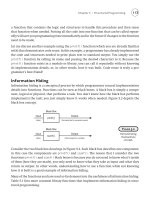
Figure 4.14 illustrates a service example, with 64 kbps DL data and associated dedi-
cated in-band signaling at 2.5 kbps (both rates measured at the Transport Channel SAP
between the MAC and PHY layers).
Specifically, data arrives at the transport channel DCH/T in Transport Blocks of size
1280 bits within a TTI of 20 ms (yielding 1280/20 = 64 kbps data rate). The in-band
signaling data arrives at a different transport channel DCH/T in Transport Blocks of size
100 bits within a TTI of 40 ms (yielding 100/20 = 2.5 kbps rate). Both these transport
channels are to be multiplexed into 5 physical channels, where each physical channel is
characterized by a single timeslot supporting 5 channelization codes with SF = 16 and
radio burst Type-1 (i.e. Midamble 512 chips). 16 bits are used per timeslot for TFCI.
Since the TTIs of the two Transport Channels to be multiplexed are different, the
multiplexing has to be performed over the larger TTI, namely 40 ms, which contains two
Transport Blocks of Traffic Data and one Transport Block of Signaling Data. Each of the
Traffic Data Transport Blocks is CRC coded with 16 CRC bits, and further coded with
Rate 1/3 Turbo Code, which increases the size 3- fold. 12 Trellis termination bits are
added and interleaved. The resulting 3900 bits are split into two radio segments, so that
they may be transmitted over two radio frames.
Similarly, the Signaling Data Transport Block is CRC coded with 12 CRC bits, and
Convolutionally coded with Rate 1/2 and 8 Trellis Coding bits. The resulting 240 bits are
interleaved.
The Radio Segments corresponding to the Traffic and Signaling Data are now punctured
as shown in order to produce four 1204 bit blocks, which are then interleaved a second
time and packed into five radio bursts (multicode transmission) after inserting TCFI fields.
4.4.2 Inter-Layer Communication
The Physical Layer interfaces with the Medium Access Control (MAC) sublayer of Layer
2 and the Radio Resource Control (RRC) sublayer of Layer 3 as depicted in Figure 4.15.
Communication between the Physical Layer and MAC is performed by means of PHY
primitives. The PHY primitives enable the transfer of transport blocks over the radio inter-
face and indicate the status of Layer 1 to Layer 2. Communication between the Physical
62 TDD Radio Interface
Information data
1280
1280
CRC attachment
Turbo Coding 1/3
[(640 × 2) +16] × 3 = 3888
12
Trellis-Termination
1st Interleaving
3888 bit/20 ms
3900 bit/20 ms
Puncturing
Rate matching
1950 bit punct. to 1150 bit
puncturing-level: 41%
5 RU → 244 × 5 =
1220 Bits available
gross 1220 bit
-TFCI -16 bit
-Signal. -54 bit
punc. to 1150 bit
SF = 16
114 114
88512
chips
88512
chips
88512
chips
88512
chips
Service Multiplex.
2nd Interleaving
128016 16
1280
12
964
100 12
8
Tail
CRC
MAC-Header
112
120 × 2 = 240
Conv. Coding 1/2
1150 1150 1150 1150
TF
CI
TF
CI
TF
CI
16
DCCH
1150 1150 1150 1150 54 54 54 54
54 54 54 54
1204 1204 1204
Slot segmentation
1204
1204
16
1204
16
1204 1204
TFCI
Puncturing 10%
Rate Matching (216)
114 114 114 114 114 114
Radio Frame #1 Radio Frame #2 Radio Frame #3 Radio Frame #4
MA
MA
MA
MA
1st Interleaving (240)
122 122
122 122 122 122 122 122
MA MA
MA
MA
122 122
122 122
122 122
122 122
MA
MA
MA
MA
122 122 122 122 122 122 122 122
MA MA
MA
MA
122 122 122 122 122 122 122 122
MA MA
MA
MA
RF-segmentation
1950 1950 1950 1950
1950 bit punct. to 1150 bit
puncturing-level: 41%
5 RU → 244 × 5 =
1220 Bits available
gross 1220 bit
-TFCI -16 bit
-Signal. -54 bit
punc. to 1150 bit
[(640 × 2) +16] × 3 = 3888
3888 bit/20 ms
3900 bit/20 ms
TF
CI
TF
CI
TF
CI
TF
CI
TF
CI
TF
CI
TF
CI
TF
CI
TF
CI
Figure 4.14 Service Example of 64 kbps Traffic and 2.5 kbps Signaling Data
Physical Layer
Medium Access Control
(MAC)
Radio Resource Control (RRC)
PHY primitives
Layer 1
Layer 2
Layer 3
CPHY primitives
Figure 4.15 Interfaces between Physical and Higher Layers
Layer 2 Structure 63
Layer and RRC is performed by means of CPHY primitives. The CPHY primitives enable
the control of the configuration of the Physical Layer. Since these primitives are only for
internal communications between layers in the UE or the Network, they are not subject
to standardization and are vendor dependent. As such, what follows should be considered
as examples only.
The PHY primitives include primitives to request and to indicate the receipt of Layer
1 SDUs respectively and are submitted every TTI for each Transport Channel.
There are two classes of CPHY primitives, namely Status primitives and Control prim-
itives. Among the Status primitives are the Synchronization primitives, which indicate to
the RRC that the Layer 1 synchronization is achieved or lost. The Measurement primitives
enable RRC to request measurements and the Physical Layer to report measurements. For
UE, these primitives specify measurements such as: PCCPCH RSCP (Received Signal
Code Power), Timeslot ISCP, SIR (Signal to Interference Ratio), Carrier RSSI (Received
Signal Strength Indicator), Transport Channel BLER (Block Error Rate), Transmitted
Power, etc. For the UTRAN, the measurement parameters include: Received Total Wide-
band Power, Transmitted Carrier Power, Transmitted Code Power, Transport Channel
BER, Rx Timing Deviation, Timeslot ISCP, RSCP, Round Trip time, SIR, PRACH/P Prop-
agation Delay, etc. The CPHY Control primitives include those for setting up/releasing
Transport Channels, and Radio Links.
4.5 LAYER 2 STRUCTURE
As shown in Figure 4.3, the structure of Layer 2 (Radio Link Layer) consists of a number
of protocol entities, namely MAC, RLC, PDCP, and BMC. Furthermore, Layer 2 provides
Services to Layer 3 via Radio Bearers. The intermediate Service Access Points between
the MAC and RLC protocol entities are referred to as Logical Channels.
4.5.1 Logical Channels
Logical Channels are classified according to the type of information that is transferred.
The set of Logical Channel types is listed in Table 4.1, and they are briefly described here.
The first group of Logical Channels is Control c hannels, which are used for transfer of
control plane information only:
• The Broadcast Control Channel (BCCH/L) is a downlink channel for broadcasting
system control information.
• The Paging Control Channel (PCCH/L) is a downlink channel that transfers paging
information. This channel is used when the network does not know the location cell of
the UE, or when the network knows the location cell of the UE but the UE does not
have a signaling connection to the network. (Specifically, the Paging Control Channel
is used when the UE is in the CELL
PCH or URA PCH state of RRC connected mode
or UE is in RRC idle mode. These are described later in Section 4.7.1.)
• The Common Control Channel (CCCH/L) is a bi-directional channel for transmitting
control information between the network and UEs. This channel is commonly used by
the UEs having no RRC connection with the network and by the UEs when accessing
a new cell after cell reselection.
64 TDD Radio Interface
• The Dedicated Control Channel (DCCH/L) is a point-to-point bi-directional chan-
nel that transmits dedicated control information between a UE and the network. This
channel is established through RRC connection set-up procedure.
• The Shared Channel Control Channel (SHCCH/L) is a bi-directional channel that
transmits control information for uplink and downlink shared channels between network
and UEs.
The second group of Logical Channels is Traffic Channels, which are used for the transfer
of user plane information only:
• Dedicated Traffic Channel (DTCH/L) is a point-to-point channel, dedicated to one
UE, for the transfer of user information. A DTCH can exist in both uplink and downlink.
• Common Traffic Channel (CTCH/L) The Common Traffic Channel (CTCH/L) is a
point-to-multipoint unidirectional channel for transfer of dedicated user information for
all or a group of specified UEs. It is used primarily for sending Broadcast and Multicast
information.
While the information carried by each of above logical channels is self-evident, the
information carried by the Broadcast Channel deserves elaboration. The Broadcast Logical
Channel carries critical system information that is needed by the UEs, the details of which
are included in Appendix 4.1.
4.5.2 Radio Bearers
Radio Bearer is a service abstraction between Layer 3 and Layer 2. It represents a data
stream provided by the RLC layer for transfer of user data between User Equipment and
Serving RNC. A Radio Bearer is specified by the RLC, PDCP and MAC information as
well as information about mapping the RB to Logical and Transport Channels as follows
[6, Sections 10.3.4.16–10.3.4.24]:
• RLC Size and Mode (AM/UM/TM)
• PDCP Information
• Logical Channel Identity
• MAC Logical Channel Priority
• Transport Channel Type and Identity
• Transport Format Parameters.
The RLC modes AM/UM/TM refer to Acknowledged Mode/Unacknowledged Mode/
Transparent Mode and are further described in Section 4.6.2. A Radio Bearer is identified
by a number from 0–31 [6]. Radio Bearers RB0 through RB3 (and optionally RB4) are
used for RRC Signaling Messages and hence are referred as Signaling Radio Bearers.
Their typical use is as follows:
• Signaling Radio Bearer RB0 is used for all messages sent on the CCCH/L with RLC-TM
for Uplink and RLC-UM for Downlink.
Layer 2 Communication 65
• Signaling Radio Bearer RB1 is used for all messages sent on the DCCH/L, with
RLC-UM.
• Signaling Radio Bearer RB2 is used for all messages sent on the DCCH/L, with
RLC-AM, except for the RRC messages carrying higher layer (NAS) signaling. These
messages are carried using Signaling Radio Bearer RB3 (and optionally Signaling Radio
Bearer RB4) with RLC-AM.
The UE and UTRAN select which Signaling Radio Bearer to use according to the message
type to be sent and the type of Logical Channel (DCCH/L or CCCH/L). For example,
RB0 is used by the UE in idle mode to send an ‘RRC Connection Request’. In connected
mode, the UE uses RB1, RB2 or RB3, with the exception of the RRC messages ‘Cell
Update’ and ‘URA Update’, which are sent in RB0 (CCCH). (These RRC messages are
explained further in Section 4.7.1).
4.6 LAYER 2 COMMUNICATION
First, we recall the notions of Protocol Data Units (PDUs) and Service Data Units (SDUs).
The term PDU refers to the block of data exchanged between peer protocol entities. It
is also a block of data exchanged between adjacent protocol entities in a protocol stack.
The term SDU refers to the block of data serviced internally by a protocol entity, see
Figure 4.16.
4.6.1 Medium Access Control (MAC) Protocol
4.6.1.1 MAC Architecture
The MAC layer controls the mapping of various Logical Channels onto Transport
Channels. Depending on the type of Transport Channel being controlled, three types
of MAC protocol entities are identified. They are termed MAC-d, MAC-c/sh and MAC-
b for Dedicated, Common/Shared and Broadcast Transport Channels respectively. The
Layer N SDU = Layer (N +1) PDU
One Layer (N + 1) PDU
SDU Processing
Layer N PDU generation
One or More Layer N
PDUs
LAYER N
One Layer (N + 1) PDU
LAYER N
One or More Layer N
PDUs
Figure 4.16 Illustration of PDU, SDU Concepts
66 TDD Radio Interface
MAC-d
FACH RACH
DCCH DTCHDTCH
DSCH DCH DCH
CTCH
MAC Control
USCH
MAC-shMAC-c
CCCH
SHCCH
PCCH
PCH FACH
Logical Channels
Transport Channels
Logical Channels
Transport
Channels
FACH RACH
DCCH DTCHDTCH
DSCH
MAC Control MAC Control
Iur or local DCH DCH
MAC-d
USCH
MAC-shMAC-c
CCCH CTCH SHCCH
PCCH
FAC HPCH
Figure 4.17 MAC Architecture: UE (top) and RNC (bottom)
Common/Shared Transport Channels include PCH/T, FACH/T, RACH/T, DSCH/T and
USCH/T. Figure 4.17 depicts the architecture for MAC-d and MAC-c/sh in the UE and
in the RNC. Observe that there are multiple Dedicated MAC protocol entities at the RNC,
each instance corresponding to a particular UE.
4.6.1.2 MAC Services and Functions
MAC Services to upper layers are:
1. Data transfer: Two Peer MAC entities communicate by exchanging MAC PDUs in
a transparent manner. (That is, there is no error correction, no retransmissions, etc.
These are services provided by higher (sub-)layers.)
2. Reallocation of radio resources and MAC parameters: This service performs the exe-
cution of radio resource reallocation at the request of the RRC protocol and change
Layer 2 Communication 67
of MAC parameters, such as transport format (combination) sets, transport channel
type, etc.
3. Reporting of measurements: Local measurements such as traffic volume and quality
indication are reported to the RRC protocol.
The MAC protocol provides the above services by implementing the following ‘MAC
Functions’:
1. Mapping between Logical Channels and Transport Channels: The MAC is responsible
for mapping of Logical Channel(s) onto the appropriate Transport Channel(s).
2. Selection of appropriate Transport Format for each Transport Channel depending on
instantaneous source rate: Given the Transport Format Combination Set assigned by
RRC, MAC selects the appropriate transport format for each active transport channel
depending on the source rate. The control of transport formats ensures efficient use of
transport channels.
3. Priority handling between data flows of one UE: When selecting between the Transport
Format Combinations in the given Transport Format Combination Set, priorities of the
data flows to be mapped onto the corresponding Transport Channels can be taken into
account. Priorities may be given based on the attributes of Radio Bearer services and
RLC buffer status.
4. Priority handling between UEs by means of dynamic scheduling: In order to utilize
the spectrum resources efficiently for bursty data, a dynamic scheduling function may
be applied. This is done by MAC priority handling on common and shared Trans-
port Channels. For dedicated Transport Channels, a dynamic scheduling function is
implicitly included as part of the reconfiguration function of the RRC protocol.
5. Identification of UEs on common transport channels: When a particular UE is addressed
on a common downlink channel, or when a UE is using the RACH/T, there is a need
for inband identification of the UE. Since the MAC layer handles the access to, and
multiplexing onto, the Transport Channels, the identification functionality is naturally
also placed in MAC.
6. Multiplexing/demultiplexing of upper layer PDUs into/from transport blocks delivered
to/from common/dedicated Transport Channels.
7. Traffic volume measurement: MAC layer measures the traffic volume on logical chan-
nels and reports to RRC protocol. Based on the reported traffic volume information,
RRC performs transport channel switching decisions.
8. Ciphering: This function prevents unauthorized acquisition of data. Ciphering is per-
formed in the MAC layer for transparent RLC mode. Details of the security architecture
are specified in [4].
Figures 4.18 and 4.19 depict how the MAC/d and MAC/c functions are implemented at
the UE and the RNC.
4.6.1.3 MAC Peer-to-Peer Communication
As stated previously, two Peer MAC entities communicate by exchanging MAC PDUs in
a transparent manner. (That is, there is no error correction, no retransmissions, etc. These
are services provided by higher (sub-)layers.)
68 TDD Radio Interface
DCCH DTCH DTCH
DCH
Note: Ciphering is performed in MAC-d only for transparent RLC mode
DCH
C/T
MUX
MAC-d
to MAC-sh
to MAC-c
Ciphering
C/T
MUX
MAC Control
Channel switching
UL: TFC selection
Deciphering
C/T
MUX
TCTF Target Channel Type Field
CTCH
MAC-c
MAC – Control
to MAC –d
CCCH
UL:TF
selection
ASC Selection
Scheduling/Priority
Handling
TCTF MUX
FACH RACHFAC H
BCCH
add/read
UE Id
SHCCH (TDD only)PCCH
PCH
Figure 4.18 MAC Processing at the UE
In the UE for the uplink, all MAC PDUs delivered to the physical layer within one
TTI are defined as a Transport Block Set (TBS). This consists of one or several Transport
Blocks, each containing one MAC PDU. The Transport Blocks are transmitted in the
order as delivered from RLC. When MAC multiplexes RLC PDUs from different logical
channels, the order of the different Logical Channels is set by the MAC protocol priorities.
Layer 2 Communication 69
DCCH
UE
DTCH DTCH
DCH DCH
MAC-d
to MAC-c
to MAC-sh
MAC-Control
Deciphering
C/T
MUX
DL scheduling/
priority handling
Ciphering
Flow Control
MAC–c /
MAC-d
C/T MUX
/ Priority
setting
C/T MUX
/ Priority
setting
Channel switching
CTCH
FAC H
MAC-c
to MAC –d
RACH
MAC – Control
CCCH
Flow Control
MAC-c / MAC-d
FAC H
UE Id
MUX
TCTF MUX
BCCH SHCCCHPCCH
PCH
TFC selection
Scheduling/Priority Handling/
CTCH: CB- Scheduling
Flow Control
MAC–sh/
MAC-d
Figure 4.19 MAC Processing at RNC
A MAC PDU consists of an optional MAC header and a MAC Service Data Unit
(MAC SDU), as shown in Figure 4.20. Both the MAC header and the MAC SDU are
of variable size. The content and the size of the MAC header depend on the type of
the Logical Channel, and in some cases none of the parameters in the MAC header are
needed. The size of the MAC-SDU depends on the size of the RLC-PDU.
• Target Channel Type field: The TCTF field is a flag that provides identification of the
Logical Channel class on FACH/T and RACH/T Transport Channels, i.e. whether it
70 TDD Radio Interface
MAC SDUTCTF UE-Id
UE-Id
Type
C/T
Header Data
Figure 4.20 MAC PDU
carries BCCH/L, CCCH/L, CTCH/L, SHCCH/L or dedicated Logical Channel infor-
mation. The size of the TCTF field of FACH/T and RACH/T is 3 or 5 bits and 2 or 4
bits respectively.
• C/T field: The C/T field provides identification of the Logical Channel instance when
multiple Logical Channels are carried on the same Transport Channel. The size of the
C/T field is fixed to 4 bits, allowing 15 Logical Channels to be distinguished.
• UE-Id: The UE-Id field provides an identifier of the UE on common Transport Channels.
The following types of UE-Id are defined:
• the 32-bit-long UTRAN Radio Network Temporary Identity (U-RNTI);
• the 16-bit-long Cell Radio Network Temporary Identity (C-RNTI).
• UE-Id Type: The 2 bit UE-Id Type field specifies whether the UE Id is U-RNTI or
C-RNTI.
Figure 4.21 below shows some example cases of MAC PDU:
4.6.1.4 MAC Layer-to-Layer Communication
MAC communicates with the upper layers (RLC and RRC) using the so-called ‘primi-
tives’: (communication with the lower layer is described in the section on Layer 1, namely
Section 4.4.2). As stated earlier, these primitives are not subject to standardization and
are vendor dependent. The following are examples only, see Figure 4.22.
The RLC layer uses the MAC-DATA primitives to send and receive MAC SDUs’.
These primitives specify an RLC-PDU or an RLC message, RLC Buffer Occupancy,
which indicates the amount of data available for transmission/retransmission in the RLC
layer, Timing Deviation of RACH transmissions, etc.
MAC SDU
Single DTCH/L or DCCH/L mapped to DCH/T;
BCCH/L mapped to BCH/T;
PCCH/L mapped to PCH/T
MAC SDU Multiple DTCH/L or DCCH/L mapped to DCH/T
MAC SDU
Single DTCH/L or DCCH/L mapped to RACH/T or FACH/T;
Single DTCH/L or DCCH/L mapped to DSCH/T or USCH/T
MAC SDU
BCCH/L mapped to FACH/T;
CTCH/L mapped to FACH/T;
CCCH/L mapped to FACH/T or RACH/T
C/T
TCTF UE-Id
UE-Id
Type
TCTF
Figure 4.21 Example MAC PDU Formats
Layer 2 Communication 71
Radio Link Control
(RLC)
Radio Resource Control (RRC)
MAC primitives
Layer 2
Layer 3
CMAC
primitives
Medium Access Control
(MAC)
Figure 4.22 MAC Inter-Layer Primitives
RRC uses CMAC-CONFIG primitives to set up, configure and release logical chan-
nels. These primitives include UE Information elements, RB information elements (such
as Transport Channel Identity, Logical Channel Identity and Logical Channel Priority),
Transport Channel Information Elements, RACH/T transmission control elements etc.
Similarly, RRC uses CMAC-MEASUREMENT primitives to manage measurements,
such as traffic volume measurements. These primitives specify parameters such as Mea-
surement Mode (Periodic or Event Triggered), Reporting Interval, Trigger Thresholds,
Averaging Interval, etc.
4.6.2 Radio Link Control (RLC) Protocol
4.6.2.1 RLC Architecture
The RLC protocol consists of three entities supporting three types of Layer 2 data transfer.
They are Transparent Mode (TM), Unacknowledged Mode (UM), and Acknowledged
Mode (AM) RLC entities, see Figure 4.23.
Each RLC UM, and TM entity uses one Logical Channel to send or receive data PDUs.
An AM RLC entity can be configured to use one or two Logical Channels to send or
Transm.
Tr-Entity
Transm.
UM-Entity
Receiv.
UM-Entity
Receiv.
Tr-Entity
AM-Entity
Transmitting side Transmitting sideReceiving side
MS Radio Interface UTRAN
RLCUppe Layers MAC
Receiving side
Transm.
Tr-Entity
Transm.
UM-Entity
Receiv.
UM-Entity
Receiv.
Tr-Entity
AM-Entity
Figure 4.23 RLC Architecture
72 TDD Radio Interface
receive data and control PDUs. If two Logical Channels are configured, they are of the
same type (DCCH or DTCH). In Figure 4.23, the dashed lines between the AM entities
illustrate the possibility to send and receive RLC PDUs on separate Logical Channels,
e.g. control PDUs on one and data PDUs on the other.
4.6.2.2 RLC Services and Functions
The RLC sublayer provides the following services to the upper layers [1]: Data transfer
Service in Transparent, Unacknowledged and Acknowledged Modes; Maintenance of QoS
as defined by upper layers and Notification of unrecoverable errors. These services are
implemented by the following central functions:
• Functions common to TM, UM and AM: Segmentation and reassembly; Transfer of
user data; and SDU discard.
• Additional Functions common to UM and AM: Ciphering; Sequence number check.
• Additional Functions exclusive to AM: In-sequence delivery of upper layer PDUs;
Duplicate detection; Error correction; Flow Control; Protocol error detection and
recovery.
We now provide a brief description of these RLC functions:
1. Segmentation and reassembly: This function performs segmentation/reassembly of
variable-length upper layer PDUs into/from smaller RLC PDUs. The RLC PDU size
is adjustable to the actual set of transport formats. However, the PDU size is fixed for
AM mode.
2. Transfer of user data: This function is used for conveyance of data between users
of RLC services, using acknowledged, unacknowledged and transparent data transfer
modes. QoS setting controls type of transfer of user data.
The following functions are employed in the transfer of user data:
1. Transparent data transfer: This service transmits RLC PDUs without adding any RLC
protocol information (header).
2. Unacknowledged data transfer. This servic e transmits RLC PDUs with protocol infor-
mation (header), but does not guarantee delivery to the peer entity. The unacknowl-
edged data transfer mode has the following characteristics:
(a) Detection of erroneous data: The RLC sublayer delivers only those SDUs to the
receiving upper layer that are free of transmission errors by using the sequence-
number check function.
(b) Immediate delivery: The receiving RLC sublayer entity delivers a SDU to the
upper layer receiving entity as soon as it arrives at the receiver.
3. Acknowledged data transfer. This service transmits RLC PDUs and guarantees delivery
to the peer entity. When the receiving RLC is unable to deliver the data correctly, the
RLC at the transmitting side is notified. For this service, both in-sequence and out-of-
sequence delivery are supported. In many cases, an upper layer protocol can restore
the order of its PDUs. As long as the out-of-sequence properties of the lower layer
Layer 2 Communication 73
are known and controlled, allowing out-of-sequence delivery can save memory space
in the receiving RLC. In this case, the upper layer protocol would not immediately
request retransmission of a missing PDU. The acknowledged data transfer mode has
the following characteristics:
(a) Error-free delivery: Error-free delivery is ensured by means of retransmission. The
receiving RLC entity delivers only error-free SDUs to the upper layer.
(b) Unique delivery: The RLC sublayer delivers each SDU only once to the receiving
upper layer using duplication detection function.
(c) In-sequence delivery: RLC sublayer provides support for in-order delivery of
SDUs, i.e. RLC sublayer delivers SDUs to the receiving upper layer entity in the
same order as the transmitting upper layer entity submits them to the RLC sublayer.
(d) Out-of-sequence delivery: As an alternative to in-sequence delivery, RLC entity
may also deliver SDUs to the upper layer in different order than submitted to RLC
sublayer at the transmitting side.
4. Notification of unrecoverable errors. RLC notifies the upper layer of errors that cannot
be resolved by RLC itself within the maximum allowed retransmissions, subject to
delay requirements.
5. Flow control: This function allows an RLC receiver to control the rate at which the
peer RLC transmitting entity may send information.
6. Ciphering: This function prevents unauthorized acquisition of data. Ciphering is per-
formed in RLC layer for non-transparent RLC mode. Details of the security architecture
are specified in [4].
Other functions include Concatenation of successive RLC SDUs, Padding of RLC PDUs,
Detection of duplicate RLC PDUs, checking the Sequence Number of RLC PDUs in
reassembling an RLC SDU, detection and recovery from RLC protocol failure, etc.
4.6.2.3 RLC Peer-to-Peer Communication
The basic mechanism of Transparent Mode RLC communication is shown in Figure 4.24.
The transmitting TM-RLC entity receives RLC SDUs from upper layers. All received
RLC SDUs must be of a length that is a multiple of one of the valid TMD (Transparent
Mode Data) PDU lengths used by the lower layer. If an RLC SDU is larger than the
TMD PDU size, and segmentation has been configured by upper layers, the transmitting
TM RLC entity segments RLC SDUs to fit the TMD PDU size. No RLC headers are
added in TM. All the TMD PDUs carrying one RLC SDU are sent in the same TTI, and
no segment from another RLC SDU are sent in this TTI. The resulting TMD PDUs are
submitted to the lower layer as shown in Figure 4.24.
The receiving TM-RLC entity receives TMD PDUs through the configured logical
channels from the lower layer. If segmentation is configured by upper layers, all TMD
PDUs received within one TTI are reassembled to form the RLC SDU. If segmentation is
not configured by upper layers, each TMD PDU is treated as a RLC SDU. The receiving
TM RLC entity delivers RLC SDUs to upper layers through the TM-SAP.
The basic mechanism of Unacknowledged Mode RLC communication is shown in
Figure 4.25 The transmitting UM-RLC entity receives RLC SDUs from upper layers
through the UM-SAP. If the RLC SDU is larger than the length of available space in the
74 TDD Radio Interface
Transmitting
TM- RLC
entity
Transmission
buffer
Segmentation
TM-SAP
CCCH/DCCH/DTCH/SHCCH – UE
BCCH/PCCH/DCCH/DTCH – UTRAN
Receiving
TM- RLC
entity
Reception
buffer
Reassembly
TM-SAP
Radio Interface (Uu)
CCCH/DCCH/DTCH/SHCCH – UTRAN
BCCH/PCCH/DCCH/DTCH – UE
UE/UTRAN
UTRAN/UE
Figure 4.24 Transparent Mode RLC Entity Peer-to-Peer Communication
UMD (Unacknowledged Mode Data) PDU, the transmitting UM RLC entity segments
the RLC SDU into UMD PDUs of appropriate size. An RLC header is appended and
ciphering is done before submitting the UMD PDU to the lower layers for transmission.
The receiving UM-RLC entity receives UMD PDUs through the configured logical
channels from the lower layer. The receiving UM RLC entity deciphers (if ciphering
is configured and started) the payload of the received UMD PDUs. It removes RLC
headers from received UMD PDUs, and reassembles RLC SDUs (if segmentation and/or
concatenation has been performed by the transmitting UM RLC entity). RLC SDUs are
delivered by the receiving UM RLC entity to the upper layers through the UM-SAP.
The basic mechanism of Acknowledged Mode RLC communication is shown in
Figure 4.26. The AM RLC entity can be configured to utilize one or two logical channels.
Figure 4.26 shows the model of the AM RLC entity when one logical channel (shown as a
solid line) and when two logical channels (shown as dashed lines) are used. If one logical
channel is configured, the transmitting side of the AM RLC entity submits AMD (AM
Data) and Control PDUs to the lower layer on that logical channel. The RLC PDU size
is the same for AMD PDUs and Control PDUs. If two logical channels are configured in
the uplink, AMD PDUs are transmitted on the first logical channel, and Control PDUs are
transmitted on the second logical channel. If two logical channels are configured in the
downlink, AMD and Control PDUs can be transmitted on any of the two logical channels.
Layer 2 Communication 75
Transmitting
UM RLC
entity
Transmission
buffer
UM-SAP
Receiving
UM RLC
entity
Reception
buffer
UM-SAP
Radio Interface (Uu)
Segmentation and
Concatenation
Ciphering
Add RLC header
Reassembly
Deciphering
Remove RLC
header
DCCH/DTCH – UE
CCCH/SHCCH/DCCH/DTCH/CTCH – UTRAN
DCCH/DTCH – UTRAN
CCCH/SHCCH/DCCH/DTCH/CTCH – UE
UE/UTRAN
UTRAN/UE
Figure 4.25 Unacknowledged Mode RLC Entity Peer-to-Peer Communication
Transmission
buffer
Retransmission
buffer and
management
MUX
Set fields in PDU Header (e.g. set poll
bits) and piggybacked STATUS PDU
RLC Control Unit
Received
acknowledgements
Acknowledgements
DCCH/
DTCH
AM-SAP
DCCH/
DTCH
DCCH/
DTCH
AM RLC entity
Demux/Routing
DCCH/
DTCH
DCCH/
DTCH
DCCH/
DTCH
Reception buffer
and Retransmission
management
Receiving
side
Segmentation/Concatenation
Ciphering (only for AMD PDU)
Add RLC header
Reassembly
Deciphering
Remove RLC header and Extract
Piggybacked information
Piggybacked status
Optional
Transmitting side
UE/UTRAN
Figure 4.26 Acknowledged Mode RLC Entity Peer-to-Peer Communication
76 TDD Radio Interface
The transmitting side of the AM-RLC entity receives RLC SDUs from upper layers
through the AM-SAP. RLC SDUs are segmented and/or concatenated into AMD PDUs
of a fixed length. The segmentation is performed if the received RLC SDU is larger
than the length of available space in the AMD PDU. The AMD PDU size is a semi-static
value that is configured by upper layers and can only be changed through re-establishment
of the AM RLC entity by upper layers. The AMD PDU may contain segmented and/or
concatenated RLC SDUs. The AMD PDU may also contain padding to ensure that it is of
a valid size. Length Indicators are used to define boundaries between RLC SDUs within
AMD PDUs. After the segmentation and/or concatenation has been performed, the AMD
PDUs are placed in the Retransmission buffer.
AMD PDUs buffered in the Retransmission buffer are deleted or retransmitted based
on the status report found within a STATUS PDU or Piggybacked STATUS PDU sent by
the peer AM RLC entity. This status report may contain positive or negative acknowl-
edgements of individual AMD PDUs received by the peer AM RLC entity. The MUX
multiplexes AMD PDUs from the Retransmission buffer that need to be retransmitted,
and the newly generated AMD PDUs delivered from the Segmentation/Concatenation
function. The ciphering (if configured) is then applied to the AMD PDUs as well as Pig-
gybacked STATUS PDU. The AMD PDU header and Control PDUs are not ciphered. The
transmitting side of the AM RLC entity submits AMD PDUs to the lower layer through
either one or two DCCH or DTCH logical channels.
The receiving side of the AM-RLC entity receives AMD and Control PDUs through
the configured logical channels from the lower layer. AMD PDUs are routed to the
Deciphering Unit, where AMD PDUs (minus the AMD PDU header) are deciphered (if
ciphering is configured and started), and then delivered to the Reception buffer. The AMD
PDUs are placed in the Reception buffer until a complete RLC SDU has been received.
The Receiver acknowledges successful reception or requests retransmission of the missing
AMD PDUs by sending one or more STATUS PDUs to the AM RLC peer entity, through
its transmitting side. If a Piggybacked STATUS PDU is found in an AMD PDU, it is
delivered to the Retransmission buffer and Management Unit at the transmitting side of
the AM RLC entity, in order to purge the buffer of positively acknowledged AMD PDUs,
and to indicate which AMD PDUs need to be retransmitted. Once all the AMD PDUs
of an RLC SDU have been received, the associated AMD PDUs are reassembled by the
Reassembly Unit into a complete RLC SDU and delivered to upper layers through the
AM-SAP.
4.6.2.4 RLC Layer-to-Layer Communication
RLC communicates with the upper layers using the following ‘primitives’. See Figure
4.27 (The communication with the lower layer is described in section on MAC protocol).
The RLC-AM-DATA family of primitives is used for Acknowledged Mode operation for
sending and receiving RLC-SDUs between the RLC entity and upper layers. Similarly,
RLC-UM-DATA and RLC-TM-DATA families of primitives describe Unacknowledged
Mode and Transparent Mode operations.
The CRLC family of primitives are used by upper layers to ‘configure’, ‘suspend’ and
‘resume’ RLC entities as well as to obtain ‘status’ of RLC entities. The ‘configuration’
primitives also include ciphering-related information for AM and UM modes.
Layer 2 Communication 77
Radio Link Control
(RLC)
Radio Resource Control (RRC)
RLC primitives
Layer 2
Layer 3
CRLC
primitives
To PDCP,
BMC and
Upper Layers
of User Plane
Figure 4.27 RLC Inter-Layer Primitives
. . .
. . .
RLC
PDCP-SDU
PDCP-
sub-layer
RLC-SDU
Radio Bearers
UM-SAP
AM-SAP
C-SAP
TM-SAP
PDCP
entity
HC Protocol
Type2
HC Protocol
Type1
PDCP
entity
PDCP
entity
HC Protocol
Type1
PDCP-SAPs
SDU
numbering
HC Protocol
Type1
HC Protocol
Type2
Figure 4.28 PDCP Architecture
4.6.3 Packet Data Protocols (PDCP)
4.6.3.1 PDCP Architecture
Figure 4.28 shows the model of the PDCP within the radio interface protocol architecture
[9]. The PDCP sublayer is defined for the PS domain only. Every PS domain RAB is
associated with one RB, which in turn is associated with one PDCP entity in the PDCP
sublayer. Each PDCP entity is associated with one RLC entity.
Every PDCP entity uses zero, one or several different header compression protocol
types. In Release 4 of the 3GPP/TDD specifications, only two header compression (HC)
protocol types are supported: RFC 2507 [10] and RFC 3095 [11].
The PDCP sublayer is configured by the upper layer through the PDCP-C-SAP.