SOIL ENGINEERING: TESTING, DESIGN, AND REMEDIATION phần 1 ppsx
Bạn đang xem bản rút gọn của tài liệu. Xem và tải ngay bản đầy đủ của tài liệu tại đây (3.24 MB, 28 trang )
©2000 CRC Press LLC
S
OIL
E
NGINEERING
:
T
ESTING
, D
ESIGN
,
AND
R
EMEDIATION
Dr. Fu Hua Chen, P.E.
Honorary Member, ASCE, 1999
Boca Raton London New York Washington, D.C.
CRC Press
Edited by
M.D. Morris, P.E.
©2000 CRC Press LLC
Library of Congress Cataloging-in-Publication Data
Chen, F.H. (Fu Hua)
Soil engineering: testing, design, and remediation / Fu Hua Chen.
p. cm.
Includes bibliographical references and index.
ISBN 0-8493-2294-4 (alk. paper)
1. Soil mechanics. 2. Engineering geology. 3. Foundations. 4. Soil remediation. I. Title.
TA710.C5185 1999
624.1’51—dc21
99-23653
CIP
This book contains information obtained from authentic and highly regarded sources. Reprinted
material is quoted with permission, and sources are indicated. A wide variety of references are listed.
Reasonable efforts have been made to publish reliable data and information, but the author and the
publisher cannot assume responsibility for the validity of all materials or for the consequences of their use.
Neither this book nor any part may be reproduced or transmitted in any form or by any means,
electronic or mechanical, including photocopying, microfilming, and recording, or by any information
storage or retrieval system, without prior permission in writing from the publisher.
The consent of CRC Press LLC does not extend to copying for general distribution, for promotion,
for creating new works, or for resale. Specific permission must be obtained in writing from CRC Press
LLC for such copying.
Direct all inquiries to CRC Press LLC, 2000 Corporate Blvd., N.W., Boca Raton, Florida 33431.
Trademark Notice:
Product or corporate names may be trademarks or registered trademarks, and
are only used for identification and explanation, without intent to infringe.
© 2000 by CRC Press LLC
No claim to original U.S. Government works
International Standard Book Number 0-8493-2294-4
Library of Congress Card Number 99-23653
Printed in the United States of America 1 2 3 4 5 6 7 8 9 0
Printed on acid-free paper
©2000 CRC Press LLC
Foreword
A true Renaissance man, Fu Hua Chen was educated in both China and the United
States. Returning to his homeland to contribute to its struggle against Japanese
attrition, he was chief engineer on the Burma Road. That artery held together the
victorious Allied campaign to end World War II on the Asian mainland.
After the Tibet Highway, the Ho Chi Minh Trail, and other large China projects,
Dr. Chen brought his family to the U.S. to build a better life. Successful in that, he
then devoted his remaining years to returning to his community, his society, and his
profession some of the benefits American life had provided for him.
Acknowledged as the world’s authority on expansive soils, Dr. Chen published
books on that and other aspects of geotechnical engineering, and a riveting autobi-
ography. He wanted the top rung of his career ladder to be his guide for constructors
and consultants to demystify soils and foundation engineering. It is a plain-talk effort
to help builders understand and deal with that complex facet so vital to construction.
With the publication of this book, Dr. Chen has achieved that goal, to top off a
monumental career that ended peacefully among his family in his 87th year.
M.D. Morris, P.E.
Advisory Editor
Chen, Fu Hua
21 July 1912 — 5 March 1999
Civil Engineer, Author, Educator, Humanitarian
©2000 CRC Press LLC
Introduction
When I was at the University of Michigan in 1935, I took a course on soils with
Professor Hogentogler. He had just completed a book entitled
The Engineering
Properties of Soil.
At that time, soil mechanics was not known. I talked to Dr.
Terzaghi at Vienna in 1938; he assured me that he had nothing to do with the term
“soil mechanics.” We all realized that the term “mechanics” is associated with
mathematics. By using the term “mechanics” with soil, the academicians firmly
linked engineering with mathematics. It appears that in order to understand soil, one
must understand “elasticity,” “diffusion theory,” “finite element” and other concepts.
After several years of dealing with foundation investigation, most consultants realize
that soil engineering is an art rather than a science as the academicians depicted.
In the last 40 years, no fewer than 50 books have been written on the subject
of soil mechanics. Most of them were written for use in teaching. Only a few touched
on practical applications. When engineers dealt with major complicated projects,
such as the failure of the Teton Dam or the Leaning Tower of Pisa, high technology
was required. However, 90% of the cases in which consulting engineers are involved
do not require mathematical treatment or computer analysis; they mostly need
experience. Consulting soil engineers are involved primarily with the design of
foundation for warehouses, schools, medium-rise buildings, and residential houses.
With such projects, the complete answers to soil engineering problems cannot be
resolved solely with textbook information.
The purpose of this book is to provide consulting engineers with the practical
meaning of the various aspects of soil mechanics; the use of unconfined compression
test data; the meaning of consolidation tests; the practical value of lateral pressure;
and other topics.
In addition to the technical aspect of foundation investigation, in the real world
one should be aware that the shadow of litigation hangs over the consultant’s head.
A careless statement may cost the consultant a great deal of time and money to
resolve the resulting legal involvement.
It is expected that the academicians may find many inconsistencies in this book.
However, at the same time, I expect that the book will find its way to the consulting
engineer’s desk.
©2000 CRC Press LLC
Acknowledgments
I wish to thank Professors Ralph Peck and George Sowers, geotechnical engineers
whom I greatly respect, for their encouragement in preparing this book. I have quoted
directly from their publications in many places.
I also wish to thank the American Consulting Engineers Council and the Asso-
ciation of Soil and Foundation Engineers for the benefit of using their publications.
The manuscript was edited and revised with many valuable suggestions from:
Paul Bartlett, Honorary Member, ASCE, Dean Emeritus, University of
Colorado at Denver;
Richard Hepworth, P.E., President, Pawlark and Hepworth, Consulting
Engineers;
M.D. Morris, P.E., F.ASCE, Ithaca, New York;
Dr. John Nelson, Professor, Colorado State University;
Malcolm L. Steinberg, P.E., F.ASCE, Steinberg & Associates, El Paso, Texas.
Dr. Jiang Lieu-Ching, University of Colorado at Denver, and Mr. Tom Jenkins,
writer, also helped with many details.
©2000 CRC Press LLC
To my wife Edna, with love and appreciation;
she took care of me during the preparation of this book while
I was suffering severely from emphysema.
©2000 CRC Press LLC
Table of Contents
Chapter 1
Site Investigation
Chapter 2
Subsoil Exploration
Chapter 3
Field Tests
Chapter 4
Classification and Identification
Chapter 5
Laboratory Soil Tests
Chapter 6
Foundation Design
Chapter 7
Footings on Clay
Chapter 8
Footings on Sand
Chapter 9
Footings on Fill
Chapter 10
Pier Foundations
Chapter 11
Laterally Loaded Piers
Chapter 12
Driven Pile Foundations
©2000 CRC Press LLC
Chapter 13
Drainage
Chapter 14
Slope Stability
Chapter 15
Distress Investigations
Chapter 16
Construction
Chapter 17
Legal Aspects
Chapter 18
Report Writing
0-8493-????-?/97/$0.00+$.50
© 1997 by CRC Press LLC
1
©2000 CRC Press LLC
Site Investigation
CONTENTS
1.1 General Information
1.1.1 Property
1.1.2 Accessibility
1.1.3 Records
1.1.4 Utility Lines
1.1.5 Existing Structures
1.1.6 Additions
1.2 Topography, Geology, Hydrology, and Geomancy
1.2.1 Topography
1.2.2 Geology
1.2.3 Hydrology
1.2.4 Geomancy
References
The stability and performance of a structure founded on soil depend on the subsoil
conditions, ground surface features, type of construction, and sometimes the mete-
orological changes. Subsoil conditions can be explored by drilling and sampling,
seismic surveying, excavation of test pits, and by the study of existing data.
Elaborate site investigation oftentimes cannot be conducted due to a limited
assigned budget. For very favorable sites, such investigation may not be warranted.
However, if the area is suspected of having deep fill, a high water table, or swelling
soil problems, extensive soil investigation will be necessary even for minor struc-
tures. The soil engineers should not accept jobs in problem areas without thorough
investigation. Bear in mind that in court of law, limited budgets or limited time
frames are not excuses for inadequate investigation. Differing site conditions are a
favorite tool of the contractors. They are used as the basis for extra claims on their
contracts.
Since a consulting soil engineer cannot afford to treat each site as a potential
hazard area, the amount of investigation required will generally be dictated by the
judgment and experience of the engineers. If the project is completed on time and
under budget, the consultant may still be criticized for being too conservative. On
the other hand, if problems are encountered in the project, no number of excuses
can relieve consultants of their responsibility.
©2000 CRC Press LLC
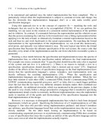
1.1
GENERAL INFORMATION
The content of this chapter has very little to do with soil engineering. However, as
a consultant, site investigation is probably one of the most important parts of the
total inquiry or the report. Average owners know very little about engineering, but
they do know a great deal about the property they own. Misrepresentation of the
observations can often cause a great deal of trouble. For instance, describing the
property as located in a low-lying area may devalue the property. Pointing out the
cracks in the building owned by someone else in the neighborhood may induce the
buyer to decrease the offer and in extreme cases may result in litigation.
Valuable information about the presence of fills and knowledge of any difficulties
encountered during the building of other nearby structures may be obtained from
talking to older residents of the area.
Much of the site investigation depends on the experience and good judgment of
the field engineer or the technician. An experienced field engineer has the sense of
a bloodhound; he is able to smell or sense a problem when he visits the site. A red
flag will be raised to call for thorough investigation. In a potential swelling soil area,
special attention should be paid to the condition and foundation system of the existing
structures.
When the site is located out of town, consulting engineering firms sometimes
assign site investigation to a technician or a field man, who has little geotechnical
experience. He may ignore some important features which should be pointed out in
the geotechnical report. An experienced technician with many years of training in
a geotechnical company can be worth more than an engineer freshly out of college
with a Ph.D. degree.
Generally, it is a small building with inadequate funding, poor planning, and a
low-bidding contractor that presents the most trouble. The owner of such a project
generally considers soil investigation as a requirement fulfillment rather than a
protection against foundation failure. Geotechnical engineers should ask for more
details regarding the site condition and proposed construction before accepting such
assignments.
1.1.1 P
ROPERTY
In most cases, the owner’s property is well defined. However, one often comes across
property that is not surveyed and not clearly marked. It is quite possible that the
field man located his test hole outside of the property line. There would be a great
deal of argument on the liability of such an incident. It is not unusual that the
engineering company has to pay for the damage. There are cases when the upper
portion of the retaining wall is within the property line, but the base of the wall
extends to the neighboring property. There are cases when the surveyor’s monument
is intentionally moved for the benefit of the owner. If the owner is on good terms
with his neighbor, nothing will happen. Otherwise, the case may wind up in court,
and the engineers may be involved.
Errors in property lines may lie undetected long after the project is completed
and forgotten. The mistake may involve the demolition of the existing structure. It
©2000 CRC Press LLC
is also possible that the client did not acquire the final title to the property and moved
ahead of schedule to order the soil test. The result in one case was the field engineer
being chased by an angry owner with a shotgun.
After the property lines have been established, permission should be obtained
from the owner to enter the property with drilling equipment. This should be in
writing, although oral permission in front of a witness may be enough. The following
is a summons filed by the owner:
“…None of the defendants asked for or obtained plaintiff’s permission to enter into
and to explore his leasehold estates, did not ask plaintiff for permission to drill or
have drilled a rotary hole into his leasehold, and did not ask plaintiff for permission
to have geophysical and geological testing conducted pertaining to his leasehold…”
It is obvious that in this case the engineering company is liable.
1.1.2 A
CCESSIBILITY
Not all properties are accessible to drilling equipment. Oftentimes, the site is covered
with crops. It is a sad sight to see crops ruined by a drilling vehicle. The engineering
company, not the owner, will wind up paying for the damage.
In mountain sites, access usually presents a problem. Before sending the drilling
equipment to the site, a general survey of the route to enter the site should be made.
Sometimes, trespassing on the neighboring properties cannot be avoided. In such
cases, permission should be obtained.
If the property is fenced, permission should be obtained to open the gate. Be
very sure that the gates are properly closed after entering or leaving. The loss of
cattle or prize horses certainly can add to the liability bill. In the eyes of the attorney,
anything lost is not replaceable.
In soft ground, as at the time of spring thaw or after continuous rain, it is a lost
effort to move the drilling equipment to the site. In order to avoid loss of time or
the cost of towing, it is always advisable to evaluate the accessibility first. An all-
terrain drill rig is able to move into places where conventional drill rigs cannot gain
access. In this case, the client should agree to pay for the additional cost or wait
until the ground has dried up.
During winter months, it is better to move the rig in the early morning when
the ground is frozen and move out before thawing. Profit and loss on a project
depend sometimes on the intelligent planning of the field engineer. Accessibility
problems should be considered before a cost estimate is offered. The margin of profit
for a consulting firm is very thin.
1.1.3 R
ECORDS
A complete record of the site investigation should be maintained by the field engi-
neer. This includes the time, date, the names of all parties involved, and all letters
and notes. Such records appear to be so obvious and unnecessary at the time, but
may turn out to be invaluable in a court of law at a later date. Dates are important
in that conditions such as water tables and climates change with time.
©2000 CRC Press LLC
Some field engineers are required to describe the site by filling out standard
questionnaires. Such lengthy questionnaires may not be desirable. Most items listed
in the questionnaires are unrelated and unnecessary, while vital issues can be
neglected. A field engineer should treat each site as an individual case and use his
observation and judgment in recording all pertinent details.
1.1.4 U
TILITY
L
INES
Before sending the drill rig to the site, subsurface utility lines should be checked
out thoroughly. Standard contracts between the consulting engineering company and
the client usually specify that the company will not be responsible for subsurface
structures not indicated on the plans furnished to the engineer. However, in the case
of accident, the information furnished to the engineering company cannot protect
the geotechnical engineer from being named as a defendant. For projects near a
metropolitan area where the site is crisscrossed with utility lines in addition to those
indicated in the existing plans, it is important to notify the telephone company, the
public service company, the water works, and the city engineer on the project. The
concerned parties will send agents to the site to accurately delineate the location of
the various lines.
In one project at the Stapleton Airport in Denver, the engineer was provided
with the location of the underground cable and all utility lines. The engineer did not
check the date on the plot, which was made several years before. During drilling, a
main fuel line was damaged, causing the delay of all air traffic. The incident was
finally settled out of court. Luckily, the geotechnical company was a relatively new
firm with few assets and was able to get away with limited payment.
In residential areas, the location of a sprinkler system should also be checked
out. The chance of hitting a 1-in. utility line with a 4-in. auger in several acres of
open field appears to be remote, but in fact such incidents have taken place over
and over.
1.1.5 E
XISTING
S
TRUCTURES
The behavior of the existing structures has an important bearing on the selection of
the proposed structure. All possible information should be obtained concerning
structures at the site and in the immediate proximity. Inquiry should be made as to
the condition of the structure, age, and type of foundation. If adjacent existing
structures have experienced water seepage problems, the possibility of a high water
table condition or a perched water condition in the area is likely to exist. The best
way to determine such a condition is to enter the lower level of the building and
look for watermarks on the wall.
It is not often that a geotechnical engineer has an opportunity to examine the
cracking of the existing building located on or near the project site. By studying the
condition of the existing structure, one will be able to tell the adequacy of the existing
foundation system. If there are cracks in the foundation system, it is certainly
important to try to determine the cause of the cracking. The cracking can be caused
©2000 CRC Press LLC
by foundation settlement, swelling of the foundation soils, or even from an earth-
quake. The age of the structure may provide the potential for distress. An experienced
geotechnical engineer treats the cracking as if it is the writing on the wall.
If the existing building is in excellent condition, this does not mean that the
existing building system can be used for the design of the new structure. The existing
structure’s foundation system could have been overdesigned. This is especially true
in the case of old structures where massive foundation systems were traditionally
used.
1.1.6 A
DDITIONS
A portion of a geotechnical consultant’s project is in addition to the existing struc-
tures. Building owners may not want to use the initial consultant and will approach
a new consultant for the geotechnical study for one of the following reasons:
The initial geotechnical firm is not available.
The fee charged by the initial engineering company is too high.
The initial recommendation of the foundation system cost is too high.
The possibility of using another foundation system.
The initial building suffered damage.
If the cost of consultation is the main reason, consideration should be given to
rejecting the job. This is on account of breaching the ethical practice. If the structure
suffered damage, the field engineer should determine as closely as possible the
following:
Damage caused by using the wrong foundation system
Damage caused by reasons other than soil
Damage caused by poor maintenance
Bearing in mind that the geotechnical engineer cannot guarantee the performance
of the structure, the second consultant should be prepared to defend the initial
consultant in a court of law rather than condemn him. It is a mistake to brag about
one’s knowledge by pointing a finger at one’s fellow engineer.
Realizing the importance of site conditions to a geotechnical consultant and the
responsibility the engineer is confronting, the Associated Soil and Foundation Engi-
neers (ASFE) proposed an agreement between the owner and the engineers as
follows:
1. The owner shall indicate to the soil engineer the property lines and is
responsible for the accuracy of markers.
2. The owner shall provide free access to the site for all necessary equipment
and personnel.
3. The owner shall take steps to see that the property is protected, inside and
out, including all landscaping, shrubs, and flowers. The soil engineer will
©2000 CRC Press LLC
not be responsible for damage to lawns, shrubs, landscapes, walks, sprin-
kler systems, or underground utilities and installations caused by move-
ment of earth or equipment.
4. The owner shall locate for the soil engineer and shall assume responsibility
for the accuracy of his representations as to the underground utilities and
installations.
Such an agreement when signed should be sufficient to protect the engineering
company, yet a talented lawyer may still find loopholes that involve the engineer.
At the same time, a large portion of geotechnical investigation is carried out
without a written contract. Small projects are carried out based on a single-page
letter or even oral agreement. In such cases, the roles of the field engineer become
more and more important. Unfortunately, the importance of the field engineer is
seldom realized by the consulting firm until a summons is served.
1.2 TOPOGRAPHY, GEOLOGY, HYDROLOGY,
AND GEOMANCY
Topography, geology, and hydrology should be treated as an integral part of soil
engineering. No soil engineer can be considered knowledgeable if he lacks
information on these subjects. No soil report can be considered complete without
touching on these subjects. No investigation can be considered satisfactory without
having such subjects in mind.
Such information can be obtained by reviewing available data, studying existing
maps, or making a reconnaissance survey. Care must be taken as to the accuracy of
such information. Oftentimes, site grading can completely alter the topography, and
development in the neighborhood can alter the hydraulic balance.
1.2.1 T
OPOGRAPHY
Topography is defined as the features of a plain or region. Generally, for larger
projects a topographic survey is available. Care must be taken with the date of the
survey and the bench mark referred to. Sometimes site grading can completely alter
the original ground features. Topography can be different if the original photogram-
metric survey was taken when the site was vegetated.
Outdated contour elevation should not be used for elevation of the top of the
drill holes without careful checking.
The shape of gullies and ravines reflects soil textures. Gullies in sand tend to
be V-shaped with uniform straight slopes. Gullies in silty soils often have U-shaped
cross-sections. Small gullies in clay often are U-shaped, while deeper ones are
broadly rounded at the tops of the slopes.
The location of natural and man-made drainage features is also of importance.
Erecting a structure across a natural gully always poses a future drainage problem.
The water level in any nearby streams and ponds should be measured and recorded.
Irrigation ditches can be dry during most of the year but can carry a large amount
of water during irrigation season. Water leaking out from the ditches and ponds can
©2000 CRC Press LLC
supply moisture to the foundation soil and cause settlement or heaving of footing
and slab. The lifting of drilled piers in an expansive soil area due to the infiltration
of water from ditches and ponds is not uncommon. The source of water may not be
detected for a long time.
Water leaking out from the ditches can also cause the cracking and dampness
of the basement slab. The location and elevation of the ditches should be included
as part of the engineering report.
Streams and nearby runoffs are important parts of the investigation. Engineers
should pay special attention to the extent of the flood plain. Such preliminary
information can usually be obtained from the U.S. Geological Survey, or the U.S.
Department of Agriculture Soil Survey reports.
The steepness of valley slopes is of special concern for sites chosen in mountain
areas. Some environmental agents classify valley slopes in excess of 30° as potential
hazard areas. Slope stability depends upon the slope’s angle, rock and soil forma-
tions, evidence of past slope movement, and drainage features. The field engineer
should be aware of the possible slope problems associated with landslides, local
slope failure, mud flow, and other problems. The vegetative cover on the slope,
shapes of tree, and the behavior of any neighboring structures should also be known.
1.2.2 G
EOLOGY
Geology is the science of the earth’s history, composition, and structure. Branches
include mineralogy, petrology, geomorphology, geochemistry, geophysics, sedimen-
tation, structural geology, economic geology, and engineering geology. The last
category is of utmost concern to the foundation engineers.
The science of geology existed long before the advance of soil engineering.
Colleges offer geology to most civil engineering students. However, some professors
in geology may have little knowledge of engineering. Consequently, the relationship
between geology and soil mechanics is seldom stressed. Students do not pay much
attention to geology and give such courses the same weight as astronomy or chemistry.
It is not until an engineer enters the field of consulting that he realizes the close
relationships between soil mechanics and geology. For average small structures that
do not require special foundation designs, geology information may not be required.
It is a mistake for consultants to put a section in their reports on geology if the
content has no bearing on the project. A section on geology in the consultant’s report
is necessary only when such information is vital to the project. Consulting firms
should have qualified staff geologists to conduct and study such projects. If the soil
engineer is not a qualified geologist, he or she should not attempt to touch the subject.
A geological assessment based on prior knowledge of the area may be required
before the study can be completed. The geological assessment can describe any
geological conditions that have to be considered before any soil testing is initiated
and recommendations for the foundation design are presented.
General surficial geology of the area includes the study of slopes, tributary
valleys, landslides, springs and seeps, sinkholes, exposed rock sections, origin of
deposit, and the nature of the unconsolidated overburden.
©2000 CRC Press LLC
An inspection of upland and valley slopes may provide clues to the thickness
and sequence of formations and rock structure. The shape and character of channels
and the nature of the soil may provide evidence of past geologic activity. An
engineering geologist should identify and describe all geologic formations visible
at the surface and note their topographic positions. The local dip and strike of the
formations should be determined and notes made of any stratigraphic relationships
or structural features that may cause problems of seepage, excessive water loss, or
slide of embankment.
Some of the geological concerns to the foundation engineers are as follows:
The bearing capacity of bedrock
The bearing capacity and settlement of windblown deposits
The expansion potential of shale
The orientation of the rock formation
The excavation difficulty
The drilling problem
The slope stability
In the mountain areas, the mapping of surficial geologic features is highly
desirable. Features to be shown on the map should include:
Texture of surficial deposits
Structure of bedrock, including dip and strike, faults or fissures, stratification,
porosity and permeability, schistosity, and weathered zones
Area of accelerated erosion deposit
Unstable slopes, slips, and landslides
Fault zones
Geologists as well as experienced engineers should be able to recognize a
potential swelling soil problem. For instance, the red siltstone formation in Laramie,
Wyoming will not pose a swelling problem, while a few miles to the west where
claystone of Pierre formation is observed, swelling can be critical. In the front range
area west of the foothills, claystone shale dips as much as 30° with the horizontal.
The joints within the rock can allow easy access of water and cause volume change.
Such problems should be carefully studied.
To assure adequate planned development of a subdivision, some state laws
require the subdivider to submit such items as:
Reports concerning streams, lakes, topography, geology, soils, and vegetation
Reports concerning geologic characteristics of the area that would signifi-
cantly affect the land use and the determination of the impact of such
characteristics on the proposed subdivision
Maps and tables concerning suitability of types of soil in the proposed
subdivision
©2000 CRC Press LLC
Careful discussion between geotechnical engineers and geologists should be
maintained during the writing of the report. The report should be presented as a
whole. It should give the client the impression that the report is from one author.
Contradictory opinions between geologists and geotechnical engineers should be
settled before the report is completed.
1.2.3 H
YDROLOGY
Hydrology is defined as the scientific study of the properties, distribution, and effects
of water on the earth’s land surface in the soil and rock. Geotechnical engineers are
dealing with water all the time. As Terzaghi stated, “without any water there would
be no use for soil mechanics.” The most common issues a geotechnical engineer
encounters are permeability, seepage, and flow in connection with ground water. For
major projects such as dams and canals, the geotechnical engineer should seek advice
and consultation from a hydrologist.
The permeability property of soil cannot be separated from the soil drainage
characteristics. The former has been researched both in theory and in the laboratory
by the academicians, yet the design and construction of the drainage installation
seldom receive proper attention from the architect. Long drainage facilities are often
shown on the design drawing by mere dotted lines. Construction of the drain facilities
is often left in the hands of the builders. It is not uncommon to see that the drains
were constructed with reverse grade or without proper outlet. Since drainage facilities
are generally installed below ground surface, the defective systems are seldom
revealed.
Details of drainage and soil moisture control will be discussed in the subsequent
chapters.
1.2.4 G
EOMANCY
Geomancy, or as what the Chinese refer to as “feng shui” or “Wind and Water” is
defined as the art of adapting the residence of the living and the dead so as to
harmonize with the cosmic breath.
The ups and downs of the profile of the land is of vital importance to the quality
of the site. The ground must be hard and solid and must have a good profile like
that of the real dragons if it is rated as a good site. The sand on the ground and the
water sources are also of great importance to the geomancer. From a geotechnical
point of view, the ideal site would be one with hard bedrock overlain by granular
deposits.
In fact, no family or business will consider building on a piece of land without
the consultation with a geomancer.
In the Western world, feng shui has been considered dogmatic faith or supersti-
tion. However, this art has been under intense study in recent years in the U.S. as
well as in European countries. It is not surprising that one will find a link between
feng shui and geotechnical engineering.
©2000 CRC Press LLC
REFERENCES
J. Atkinson,
An Introduction to the Mechanics of Soils and Foundations,
McGraw-Hill, New
York, 1993.
L. Evelyn,
Chinese Geomancy,
Times Books International, Singapore, 1979.
G.B. Sowers and G.S. Sowers,
Introductory Soil Mechanics and Foundations,
Collier-
Macmillan, London, 1970.
K. Terzaghi, R. Peck, and G. Mesri,
Soil Mechanics in Engineering Practice,
John Wiley-
Interscience Publication, John Wiley & Sons, New York, 1995.
0-8493-????-?/97/$0.00+$.50
© 1997 by CRC Press LLC
2
©2000 CRC Press LLC
Subsoil Exploration
CONTENTS
2.1 Direct Methods
2.1.1 Test Pits
2.1.2 Auger Drilling
2.1.3 Rotary Drilling
2.2 Indirect Methods
2.3 Test Holes
2.3.1 Test Hole Spacing
2.3.2 Test Hole Depth
2.3.3 Water in the Test Hole
2.4 Sampling
2.4.1 Disturbed Samples
2.4.2 Undisturbed Samples
References
Subsoil exploration is the first step in the designing of a foundation system. It consists
essentially of drilling and sampling. The process of subsoil exploration took place
long before soil mechanics was born. Present-day engineering requires thousands
of exploratory test borings to build a structure like the Great Wall of China. The
wall actually winds around the mountains, avoiding problem soil areas. Somehow
its ancient builders had a sense in selecting the good foundation soils.
Chinese legend tells the story of a commandeered laborer who died while
building the Great Wall. His wife’s lament at the foot of the wall was so moving
that the wall collapsed. We suspect now if the story is true, the wall collapsed due
to foundation failure.
Experienced engineers use soil mechanics to
confirm
their conclusions rather
than to reach their conclusions. Many factors affect the choice of a subsoil explo-
ration program; the judgment of the engineer is deemed necessary.
2.1 DIRECT METHODS
The most suitable method to perform subsoil exploration depends on the type of
soil in the general area; type of equipment available; ground water condition; type
of proposed structure; and the amount of money allocated for the exploration.
Direct methods of exploration include the digging of test pits and the use of
auger drilling or rotary drilling. Each method has its merits and its drawbacks. The
engineer must use his or her judgment based on experience and the evaluation of
©2000 CRC Press LLC
the site conditions to select the best method. Unfortunately, in most projects there
is very little choice. The driller and the available equipment are the only choices.
The engineer often must help the driller in solving the drilling problems.
2.1.1 T
EST
P
ITS
Probably the most accurate subsoil investigation method is the opening of test pits.
In a test pit, the engineer can examine in detail the subsoil strata, stratification, layer
and lens, as well as take samples at the desired location. However, the use of test
pits is limited by the following:
When the depth of the test is limited to the reach of a backhoe, generally 12 ft.
When the investigation involves basement construction that extends below
the ground level
When the water table is high, which prevents excavation
When the soil is unstable and has the tendency to collapse, this prevents the
engineer from entering the pit. Entering a test pit can involve certain risks
and the regulations of the Occupational Safety and Health Administration
(OSHA) should be observed
When the standard penetration resistance test is required
In locations where subsoil consists essentially of large boulders and cobbles, the
use of test pit investigation is most favorable. Auger drilling through boulders and
cobbles is difficult. The cost of rotary drilling may not be warranted for small projects.
The layman’s conception of subsoil investigation generally assumes that drilling
to a great depth constitutes the main portion of the cost. After drilling, the layman
thinks the remaining task of the engineer, such as testing and preparation of the
report, is of minor importance. Consequently, when no drill rig shows up at the
project site, the client feels that he has been cheated and the money paid for the
investigation is not justified. With such a philosophy, the engineering company
usually attempts to drill each project when possible instead of resorting to the use
of a backhoe.
Another possible investigation method is to drill a large-diameter caisson hole
to the required depth; a caisson rig is shown in Figure 2.1. By entering the hole, the
engineer can clearly examine the subsoil strata and undisturbed samples can be
obtained at the desired depth. However, such practice is frowned upon by OSHA
for safety reasons.
If deep excavation is required or if the soil cannot maintain the steep side slope,
sometimes the use of sheeting is necessary. The minimum size of the pit is 4
¥
4 ft,
so that a man can enter the pit. Pit excavation in this case must be carried out entirely
by manpower. The cost of such an operation is high.
2.1.2 A
UGER
D
RILLING
In auger drilling, the hole is advanced by rotating a soil auger while pressing it into
the soil, and later withdrawing and emptying the soil-laden auger. A series of augers
©2000 CRC Press LLC
and a special drilling machine for their operation have been developed by many
specialized soil exploration equipment companies.
A series of augers, or a continuous flight helical auger (Figure 2.2), are used for
drilling holes with diameters of 4 to 8 in. to a depth of 100 ft. An auger boring is
made by turning the auger the desired distance into the soil, withdrawing it, and
removing the soil for examination and sampling. As the depth increases, new auger
sections are added. It is difficult to determine the depth from which the soil dis-
charged from the auger is excavated. Consequently, in order to obtain a representative
sample or an undisturbed sample, it will be necessary to stop the drilling and replace
the auger with a sampler. The sampler can then be pushed or driven into the soil at
the desired depth.
Auger drilling can be successfully conducted in almost all types of soils and in
shale bedrock. For hard bedock such as limestone, sandstone, and granite, rotary
drilling is necessary.
The drilling machine has a folding mast with a chain-operated feed and lifts. In
wet and spongy terrain where a tire-mounted rig is not accessible, a tractor-mounted
type rig is available (Figure 2.3). More than 90% of soil exploration study today is
conducted by such a device or similar devices.
Relatively short helical augers with interchangeable cutters are used for medium-
size holes, whereas large-diameter holes up to 24 in. are excavated by means of a
disc auger.
FIGURE 2.1
Caisson rig with a rock bit.
©2000 CRC Press LLC
FIGURE 2.2
Continuous flight
hollow stem auger.
FIGURE 2.3
Tractor-mounted auger drilling rig.
©2000 CRC Press LLC
2.1.3 R
OTARY
D
RILLING
In rotary drilling the bore hole is advanced by rapid rotation of the drilling bit, which
cuts and grinds the material at the bottom of the hole into small particles. The
cuttings are removed by pumping drilling fluid from a sump down through the drill
rods and bit, up through the hole from which it flows first into a settling pond, and
then back to the main pit.
Rotary drilling with a diamond bit (Figure 2.4) can be used efficiently for drilling
through semi-hard rocks. Most truck-mounted drill rigs (Figure 2.5) can be used for
rotary drilling with little modification. Core samples are brought up by the drill and
can be visually examined. The general characteristics, particularly the percentages
of recovery, are of importance to foundation design and construction.
For consultants with limited experience with drilling, it is better to study catalogs
from various companies before deciding on the type of equipment best suited for
the job. An experienced operator is essential for handling and maintaining the costly
equipment.
2.2 INDIRECT METHODS
The geophysical method of exploration is the main indirect method of subsoil
exploration.
In subsoil investigation, the seismic method is most frequently used. Seismic
methods are based on the variation of the wave velocity in different earth materials.
The method involves generating a sound wave in the rock or soil, using a sledge-
hammer, a falling weight, or a small explosive charge, and then recording its reception
FIGURE 2.4
Diamond drill bit.
©2000 CRC Press LLC
at a series of geophones located at various distances from the shot point, as shown
in Figure 2.6. The time of the refracted sound arrival at each geophone is noted from
a continuous reader. Typical seismic velocities of earth materials in ft/sec are shown
in Table 2.1.
FIGURE 2.5
Truck-mounted drilling rig.
FIGURE 2.6
Diagram of seismic refraction test (after Moore).