Fundamentals of Clinical Ophthalmology - part 2 pot
Bạn đang xem bản rút gọn của tài liệu. Xem và tải ngay bản đầy đủ của tài liệu tại đây (538.44 KB, 23 trang )
The surgeon can make a partial thickness
incision, as for extracapsular surgery, and then
use this as the first step in the construction of
either a tri- or biplanar incision for the phaco
hand piece. The nucleus is sculpted so that the
surgeon can appreciate the difference between
the plastic cataract and the human lens.
Following initial grooving, if the surgeon still
feels confident that the cataract is within his or
her ability, then the nucleus can be rotated and
further grooving performed. If difficulties are
encountered then the phaco tip should be
removed from the eye, the incision opened, and
an extracapsular cataract extraction performed.
Having sculpted three or four nuclei most
surgeons will feel confident to continue with
phacoemulsification and proceed to nuclear
cracking with quadrant removal. The incision
should always be constructed to enable the
surgeon to perform an extracapsular extraction
at any stage should this become necessary.
Case selection
Virtually all cataracts can be removed from
the eye using phacoemulsification. The limiting
factor is not the machinery but the surgeon’s
skill. It is important that the trainer and trainee
select appropriate cases together at the
preoperative assessment stage and arrange the
theatre list accordingly.
There are a number of points to consider
when selecting cases (Box 1.1). The eye should
have a clear healthy cornea, a pupil that dilates
well, and a reasonable red reflex. A deep-set eye
or prominent brow/nose can make access difficult
while learning. Axial length should be considered
when selecting patients. Hypermetropic short
eyes present problems with a shallow anterior
chamber, whereas myopic eyes have a deep
anterior chamber. Patients with potential zonular
fragility such as those with pseudoexfoliation or a
history of previous ocular trauma should be
avoided, as should patients who will find it
difficult to lie still for an appropriate length of
time or who require awkward positioning on the
operating table.
The team approach
Adequate training must be provided for all
members of the team in the operating theatre.
A surgeon learning phacoemulsification is highly
dependent on the nurse who is setting up and
controlling the machine. For example, when the
nurse fully understands how the phaco machine
works, the surgeon need only concentrate on
the operation. However, trainees will find it less
stressful if they are familiar with how to set up
the tubing and hand pieces, and with selecting
programmes for the phaco machine. This
should be encouraged by the trainer at an early
stage on the learning curve and may be achieved
by the trainee acting as the scrub nurse,
supervised by a member of the nursing staff.
This is also an effective method of team
building.
The team needs to have a full understanding
of how training is to proceed and the time
implications for surgery. This includes the nurses,
the anaesthetist, and anaesthetic technicians.
Each team member plays a role in the training
process, and when the final piece of nucleus
disappears into the phaco tip at the end of the
surgeon’s first “complete phaco” the team should
feel that they have all shared in that success.
TEACHING AND LEARNING PHACOEMULSIFICATION
9
Box 1.1 Case selection: The ideal
training case
• Healthy cornea
• Full pupil dilatation
• Good red reflex
• Moderate cataract density
• Easy surgical access
(for example, no prominent brow)
• Average axial length
(for example, 22–25 mm)
• Lack of ocular comorbidity
(for example, pseudoexfoliation)
• Able to lie still and flat under local anaesthesia
Trainer and trainee communication
Most cataract surgery takes place under local
anaesthetic and beginners need to be taught that
the patient beneath the drape is awake.
Appropriate communication should be used
between the trainer and trainee. It is particularly
important to repress the desire for expressions of
surprise or frustration.
It may be appropriate to inform the patient
that a team of doctors is present at the operation
and that discussion or description of various
stages of the procedure may take place. This will
help to prevent the natural anxiety that is
experienced by patients who feel that a “junior
doctor” is “learning” on their eye. A useful
teaching technique is to use the first person, for
example “I rotate the nucleus now”, as an actual
instruction and to use a pre-agreed word to
indicate that instrument removal from the eye
is desired.
References
1 Leaming D. Practice styles and preferences of ASCRS
members: 1998 survey. J Cataract Refract Surg 1999;
25:851–9.
2 Desai P, Minassian DC, Reidy A. National cataract
surgery survey 1997–8: a report of the results of the
clinical outcomes. Br J Ophthalmol 1999;83:1336–40.
3 Seward HC, Davies A, Dalton R. Phacoemulsification:
risk/benefit analysis during the learning curve. Eye
1993;7:164–8.
4 Sugiura T, Kurosaka D, Uezuki Y, Eguchi S, Obata H,
Takahashi T. Creating a cataract in a pig eye. J Cataract
Refract Surg 1999;25:615–21.
5 van Vreeswijk H, Pameyer JH. Inducing cataract in post-
mortem pig eyes for cataract training purposes. J Cataract
Refract Surg 1998;24:17–18.
6 Mekada A, Nakajima J, Nakamura J, Hirata H, Kishi T,
Kani K. Cataract surgery training using pig eyes filled
with chestnuts of various hardness. J Cataract Refract
Surg 1999;25:622–5.
7 Maloney WF, Hall D, Parkinson DB. Synthetic cataract
teaching system for phacoemulsification. J Cataract
Refract Surg 1988;14:218–21.
CATARACT SURGERY
10
Phacoemulsification is a significant advance in
cataract surgery that reduces postoperative
inflammation, with early wound stability,
resulting in minimal postoperative astigmatism
and rapid visual rehabilitation. Most of these
advantages are directly attributable to the
sutureless small incision. Accordingly, incision
construction is a key component of modern
cataract surgery. In each of the steps of
phacoemulsification, the success of a subsequent
step is dependent on that preceding it. The
incision may be viewed as the first step in this
process and hence is central to the overall
success of the procedure.
In 1967 Kelman
1
demonstrated that
phacoemulsification might allow surgical incisions
to be as small as 2–3 mm in width. However,
the subsequent widespread introduction and
acceptance of intraocular lenses (IOLs)
constructed of rigid polymethylmethacrylate
necessitated an incision width of approximately
7 mm. The advantage of a small phacoemulsifi-
cation incision, with low levels of induced
astigmatism, was therefore substantially reduced.
It has been recognised that if an incision is placed
further from the optical axis, then it may be
increased in width while remaining astigmatically
neutral (Figure 2.1).
2
The need for a larger
incision was therefore partly overcome by the
development of posteriorly placed scleral tunnel
incisions
3
and innovative astigmatic suture
techniques.
4
The advent of lens implants with an
optic diameter of around 5 mm allowed these
scleral tunnels to be left unsutured, and such
incisions have been shown to be extremely
strong.
5
The development of foldable lens
materials has enabled the initial small
phacoemulsification incision to be retained.
6
This
has made it possible for a self-sealing incision to be
placed more anteriorly, in the clear cornea,
without increasing astigmatism or loss of wound
stability. Further development in hand piece
11
2 Incision planning and construction
for phacoemulsification
Figure 2.1 The “astigmatic funnel”: a series of
incisions have to shorten in width as they are placed
closer to the optic axis in order to induce the same
astigmatism.
technology has seen a reduction in phaco tip
diameter and hence incision width. Some lenses
can be inserted through these incisions that
measure less than 3 mm; however, it remains to be
seen whether this further reduction in wound size
confers a significant refractive advantage.
Incision choice
The principal decision facing a surgeon is
whether to perform a scleral tunnel incision
(STI) or clear corneal incision (CCI). The
refractive implications of these incisions are dealt
with separately below, but there are several other
factors that may influence the choice of incision.
The more anterior position and overall shorter
tunnel length of a CCI increases hand piece
manoeuvrability and allows the phaco probe
more direct access to the anterior chamber and
the cataract. Furthermore, a CCI may be less
likely to compress the irrigation sleeve of the
phaco probe and hence reduces the risk of
heating the incision, or “phaco burn”. However,
the tunnel of a CCI extends further anteriorly
than does that of a STI, and this may lead to
corneal distortion or striae from the phaco hand
piece. It has been demonstrated that incisions
in which the tunnel width and length are
approximately the same (square or near square;
Figure 2.2a) are more resistant to leakage than
are those in which the width is greater than
the tunnel length (rectangular; Figure 2.2b).
5
Hence, when a polymethylmethacrylate or
folding IOL that requires a larger incision is
used, the comparatively longer tunnel of a STI
may be more likely to provide a wound that can
remain unsutured.
A STI requires a conjunctival peritomy and
cautery to the episclera. This is time consuming
and in patients with impaired clotting, for
example those taking asprin or warfarin, it is best
avoided. Disturbance of the conjunctiva may
also compromise the success of subsequent
glaucoma drainage surgery.
7
In addition, if a
patient has a functioning trabeculectomy, then a
CCI avoids an incision of the conjunctiva and
the risk of damaging the drainage bleb. Of
course, a scleral tunnel is a prerequisite when
performing a phacotrabeculectomy.
There is some evidence to suggest that
endothelial cell loss may be lower when
phacoemulsification is performed through a
STI
8
and it may therefore be a preferable
technique in patients with poor endothelial
reserve, for example those with Fuchs’
endothelial dystrophy or following a penetrating
corneal graft. The possible need, identified
before surgery, for conversion to an expression
extracapsular technique may also influence the
choice of incision. In favour of an enlarged STI
is that it may be easier to express the nucleus
and less detrimental to the endothelium.
However, a CCI may be quicker and easier to
enlarge, at the possible risk of greater, induced
astigmatism.
Factors such as previous vitreous surgery, in
which the sclera may be scarred, and disorders
that predispose to scleral thinning and conjuctival
diseases, for example ocular cicatrical
phemphigoid, all favour a CCI. Histological
analysis has demonstrated that phacoemulsification
incisions placed in vascular tissue initiate an
early fibroblastic response and rapid healing as
compared with those in avascular corneal
tissue.
9
This may be relevant to patients for
whom rapid healing is advantageous (for
example children and those with mental
handicap) and to patients with reduced healing
(for example diabetic persons and those taking
corticosteroids).
CATARACT SURGERY
12
1.5mm
2.0mm
3.5mm
a) b)
3.5mm
2.0mm
Corneal component
Scleral component
3.5mm
Figure 2.2 Incision shapes. (a) A “square” scleral
tunnel incision. (b) A “rectangular” clear corneal
incision.
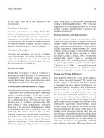
Table 2.1 summarises the comparative
advantages of STIs and CCIs. It has been
suggested that these advantages may be
combined by placing the incision over the
limbus.
10
However, the disadvantage is that
bleeding still occurs and cautery may be
required.
Incision placement
A STI is usually placed at the superior or
oblique (superolateral) position, which ensures
that the conjunctival wound is under the
patient’s upper lid. Surgeon comfort and ease of
surgery are also factors in this decision, and
these same factors influence the choice of
position for a CCI. Aside from the refractive
issues dealt with below, there may be a number
of other considerations when selecting the
placement of an incision.
Access via a temporal approach is often easier
in patients with deep-set eyes or with a
prominent brow. In these circumstances the use
of a lid speculum with a nasal rather than
temporal hinge may be helpful (Figure 2.3). Pre-
existing ocular pathology, such as peripheral
anterior synechiae, corneal scarring and pannus,
or the position of a trabeculectomy filtering bleb
may alter the selection of an incision site.
Surgically induced astigmatism
Scleral and corneal incisions both cause some
degree of corneal flattening in the meridian (or
axis) on which they are performed, with
corresponding steepening in the perpendicular
meridian, termed “surgically induced astigmatism”.
As previously stated, this effect is dependent on
the size of the incision and its proximity to the
centre of the cornea (Figure 2.1). Because a STI
is performed further from the optic axis it
induces less astigmatism than does a CCI of
equivalent width. Various STI pregroove shapes
INCISION PLANNING AND CONSTRUCTION FOR PHACOEMULSIFICATION
13
Table 2.1 Comparative advantages of scleral and corneal incisions
Incision type Advantages
Scleral tunnel incision Minimal induced astigmatism
Large sutureless incisions possible
May be combined with trabeculectomy at single site
Less endothelial cell loss
Rapid wound healing
Safe if converted to large-incision extracapsular technique
Phaco hand piece less likely to cause corneal striae and distort view
Clear corneal incision Induced astigmatism may be used to modify pre-existing astigmatism
Reduced surgical time
Less likely to compromise existing or future glaucoma filtration surgery
No risk of haemorrhage; cautery not required
Reduced risk of phaco burn (shorter tunnel)
Increased ease of hand piece manipulation
Avoids conjunctiva in diseases such as ocular cicatricial pemphigoid
Avoids sclera when scarred and/or thinned
Easy to convert to large-incision extracapsular technique
Figure 2.3 Lid speculum with nasal hinge (BD
Ophthalmic Systems).
have been described that, by altering wound
construction, attempt to minimise surgically
induced astigmatism. These include straight,
curved (limbus parallel), reverse curved (frown),
and V-shaped (chevron) incisions. However,
none of these has been clearly identified as
inducing less astigmatism.
11
The degree of induced astigmatic change and
its stability over time varies with the meridonal
axis on which the incision is placed. Both STIs
and CCIs produce the least astigmatism when
they are placed on the temporal meridian and
most astigmatism when they are placed
superiorly.
12–14
An oblique position has an
intermediate effect.
15,16
These findings reflect the
elliptical shape of the cornea and the greater
proximity of the superior limbus to its centre.
The surgically induced astigmatism reported by
several authors using different unsutured
triplanar incisions at three months is
summarised in Table 2.2. Superiorly placed
incisions are also associated with an increase in
astigmatism over time and a change toward
“against the rule” (ATR) astigmatism, with a
steeper cornea in the 180º axis.
17,18
This effect,
which is dependent on incision size, has been
attributed to the effect of gravity and pressure
from the lids.
The meridian on which an incision is placed
is therefore an important factor in surgical
planning, particularly with reference to a
patient’s pre-existing keratometric or corneal
astigmatism. It should be noted that the
spectacle refraction may be misleading because
lenticular astigmatism is negated by cataract
surgery. With increased age the majority of the
population develop ATR astigmatism. Hence, a
temporally placed incision may reduce or
neutralise this astigmatism. In a few circumstances
the incision may induce a small degree of “with
the rule” (WTR) astigmatism, with corneal
steepening in the 90° meridian. Although it is
generally preferable to undercorrect pre-existing
astigmatism and avoid large swings of axis,
19
WTR astigmatism is considered normal in
younger individuals and may confer some
optical advantage.
Reducing coexisting astigmatism
during phacoemulsification
Naturally occurring astigmatism may be
present in 14–50% of the normal population
20,21
and cataract surgery provides the opportunity to
correct this astigmatism. This improves patients’
unaided vision after surgery, reducing their
dependence on spectacles and increasing their
satisfaction. In patients with moderate levels
of pre-existing astigmatism, a reduction in
astigmatism without altering the axis may be
achieved, by placing the incision on the steep
or “plus” meridian. This is of particular
importance when using multifocal lens implants,
where astigmatism may substantially reduce the
multifocal effect.
22
In these circumstances,
modifying incision architecture may increase
the astigmatic effect of a CCI. Langerman
23
described a triplanar CCI with a deep (750 µm)
pregroove that was intended to create a limbal
“hinge” and ensure a non-leaking incision
CATARACT SURGERY
14
Table 2.2 Reported surgically induced astigmatism (SIA) in unsutured triplanar incisions at three months
Incision type Incision site Incision length (mm) SIA (dioptres) Reference
STI Superior 3·2 0·63 ± 0·43 Oshika et al.
14
5·5 1·00 ± 0·59
Oblique 3·2 0·37 ± 0·28 Hayashi et al.
15
5·0 0·64 ± 0·39
CCI Superior 3·0–3·5 0·88 ± 0·66 Long and Monica
12
Temporal 3·0–3·5 0·67 ± 0·49
3·0 0·20 ± 0·32 Rainer et al.
18
Oblique 3·0 0·39 ± 0·73
SIA vector analysis was conducted using the Jaffe method, except for Rainer et al.,
18
who used the Cravy method.
even if pressure was applied to its posterior lip
(Figure 2.4). The deep pregroove has been
noted to have a keratotomy or limbal relaxing
effect that induces more astigmatic change,
which is more pronounced as the incision length
increases.
24
When attempting to reduce astigmatism by
incision positioning, it is important to ensure
that it is accurately placed on the steep meridian.
A 30º error will simply alter the axis of
astigmatism without changing its power (if
attempting a full correction). Smaller errors
decrease the effect of the incision and change the
axis of astigmatism, albeit less dramatically.
Because torsional eye movement may occur
despite local anaesthesia, the steep axis, or a
reference point on the globe from which this axis
can be derived, should be identified or marked
before anaesthesia. The axis can also be
confirmed with intraoperative keratometry at the
start of surgery. When placing an incision on the
steep meridian of astigmatism, there are some
meridia that may necessitate the surgeon
adopting an unusual operating position or
operating with their non-dominant hand
(Figure 2.5). In such cases it may be preferable
to use a standard phacoemulsification incision in
conjunction with an incisional refractive
technique or a toric lens implant. It is relevant to
note that, when correcting astigmatism with an
incisional technique, coupling changes the
overall corneal power and larger corrections may
therefore alter the IOL biometry calculation (see
INCISION PLANNING AND CONSTRUCTION FOR PHACOEMULSIFICATION
15
Deep pregroove
incision
Figure 2.4 Wound profile of Langermann’s hinge
incision.
90˚
90˚
80˚
45˚
135˚
NO GO (45-80˚: OD / 135-170˚: OS)
- surgeon cannot place incision on steep axis
135˚
45˚
180/0˚0/180˚
90˚
Superior
Superior
OD
OS
90˚
180/0˚
170˚
0/180˚
Temporal
Temporal
GO
- surgeon can place incision on steep axis
Figure 2.5 The “no go” meridia for a right handed surgeon.
Chapter 6). Table 2.3 suggests an approach to
modifying incision type and placement in order
to avoid increasing, and possibly reduce, pre-
existing keratometric astigmatism. However,
surgically induced astigmatism varies with the
size of incision and from surgeon to surgeon,
and it may be necessary to adapt this guide on
the basis of an individual’s experience with their
preferred incision techniques.
Several techniques exist for modulating high
astigmatism intraoperatively. These include
astigmatic keratotomy, limbal relaxing incisions,
opposite CCIs, and toric IOL implantation.
Irrespective of the technique used, the astigmatic
effect of the phacoemulsification incision also
needs to be taken into account (unless it is
astigmatically neutral). Corneal video topography
should be performed before any refractive surgery
is performed to exclude the presence of irregular
astigmatism from, for example, a corneal ectatic
disease. This reaffirms the axis of astigmatism,
which should be identified or marked on the eye,
as discussed above. The surgeon’s principle aim
should be to preserve corneal asphericity and
reduce high preoperative astigmatism while
maintaining its principal meridian.
Limbal relaxing incisions are partial thickness
incisions at the limbus (the corneoscleral
junction) and have been advocated as an effective
and safe method of reducing astigmatism during
cataract surgery.
25
Compared with astigmatic
keratotomy they have the advantage of better
preserving corneal structure with more rapid
visual recovery and less risk of postoperative glare
or discomfort. They are also easier to perform
and do not require preoperative pachymetry. The
incisions can be performed at the start of
phacoemulsification or after lens implantation
(before removal of viscoelastic). With reference to
a suitable nomogram (Table 2.4) or software
program, single or paired, 6- to 8-mm long
incisions are made at the limbus centred on the
axis of corneal astigmatism. They are typically
550–600 µm deep, and preset guarded disposable
blades are available that avoid the need for an
adjustable guarded diamond blade. Astigmatic
keratotomy nomograms usually use degrees
of arc to define the incision length and require
special instrumentation. With an optic zone of
12 mm (the corneal diameter), degrees of arc
approximate to millimeters (for example, ~60° =
~6 mm), and this conveniently allows the length
of a limbal relaxing incision to be marked along
the limbus with a standard calliper. Opposite
CCIs also do not require new instrumentation or
new surgical skills.
26
The use of paired incisions
(both on the steep meridian) increases the
expected flattening effect of a single CCI, and a
mean correction of 2·25 D has been reported
(using 2·8 to 3·5-mm wide phaco incisions).
Although simple to perform, opposite CCIs
necessitate an additional penetrating incision that
may have greater potential for complications
CATARACT SURGERY
16
Table 2.3 Unsutured small incision planning in relation to pre-existing astigmatism
Pre-exisiting keratometric astigmatism Incision type and position
+ 0·75 D ATR Temporal CCI (or STI)
+ 1·00 D WTR or oblique
>+ 0·75 D ATR Langermann hinge CCI on axis
>+1·00 D WTR or oblique
Note: if > +1·75 D (ATR, WTR, or oblique) then consider an incisional refractive technique or toric intraocular lens. ATR,
against the rule; CCI, clear corneal incision; D, dioptres; STI, Scleral tunnel incision; WTR, with the rule.
Table 2.4 Limbal keratotomy nomogram
Astigmatism Incision type Length Optical zone
(dioptres) (mm)
2–3 Two LRIs 6·0 At limbus
>3 Two LRIs 8·0 At limbus
Modified Gills nomogram for limbal relaxing incisions
(LRIs) to correct astigmatism with cataract surgery.
Modified from Budak et al.
25
when compared with an alternative non-
penetrating incisional technique.
27
Implantation of a toric IOL avoids the
potential complications of additional corneal
incisions and has no effect on corneal coupling.
An example is the Staar foldable toric lens
implant, which is identical to current silicone
plate haptic lenses except on its anterior surface
there is a spherocylindrical or toric refracting
element.
28
Like all toric lenses, this requires
accurate intraoperative alignment in order to
correct astigmatism and relies on the IOL
remaining centred. Although plate haptic lenses
may rotate within the capsular bag immediately
after implantation, they show long-term rotational
stability as compared with loop haptic lenses.
29
Early postoperative reintervention may therefore
be required with plate haptic toric lenses and the
ideal toric lens design remains to be identified. A
toric IOL also has the disadvantage that the
astigmatic correction is limited to a narrow range
of powers.
Incision technique
Scleral tunnel incision technique
A conjunctival peritomy is first performed
with spring scissors and forceps (Figure 2.6a).
This is approximately the same length as the
proposed final incision width, and should be
measured and marked using a calliper
beforehand. The conjunctiva is blunt dissected
posteriorly to expose the sclera 2–3 mm behind
the limbus. It is important that this is fully
beneath Tenon’s fascia. If necessary, one or two
radial relieving incisions may be made at the ends
of the conjunctival wound to improve exposure.
The minimum cautery required to achieve
haemostasis is applied to the exposed episcleral
vessels over the proposed incision site.
The width of the incision should be marked
2 mm behind the limbus using a calliper. The
first step of the incision is to create a straight
pregroove incision of around one third scleral
thickness in depth (Figure 2.6b). Care should be
INCISION PLANNING AND CONSTRUCTION FOR PHACOEMULSIFICATION
17
a)
b)
c)
d)
Figure 2.6 Microscope view and wound profile:
steps in the construction of a scleral tunnel incision.
(a) Conjunctival peritomy. (b) Pregroove incision.
(c) Scleral and corneal tunnel. (d) Entry into the
anterior chamber with a keratome.
CATARACT SURGERY
18
taken not to cut too deeply and incise the ciliary
body. This may be avoided by using a guarded
blade with a preset cutting depth of approximately
300 µm (Figure 2.7). Disposable blades with a
fixed cutting depth are widely marketed for this
purpose. During this step, the globe can be
stabilised, and counter traction applied, by
forceps gripping the limbus near to the lateral
edge of the peritomy.
In the second step a pocket or crescent blade
is used to create the scleral tunnel. By pressing
on the posterior edge of the pregroove with the
flat base of the blade, its tip is placed into the
anterior aspect of the groove. Initially this may
require the blade to be directed relatively
downward, but as soon as the tunnel is
commenced the heel of the blade should be
lowered to the conjunctival surface to ensure an
even lamellar dissection through the sclera into
the corneal plane. The lamellar cut should proceed
smoothly and anteriorly, with a combination of
partial rotatory and side to side motions. The
lamellar dissection is continued until the tip of
the pocket blade is just visible within clear
cornea, beyond the limbus (Figure 2.6c). The
tunnel can then be extended further laterally, to
the full width of the pregroove and the desired
incision width. During creation of the scleral
pocket, counter traction can be improved by
gripping the sclera adjacent to the lateral edge of
the pregroove or its posterior lip. Neither the
fragile anterior edge nor the roof of the tunnel
should be gripped. If an extremely sharp pocket
or crescent knife is used, for example a diamond
blade, then counter traction may not be
required.
The final stage of the incision is then
performed using a keratome blade, the width of
which is matched to the diameter of the phaco
tip. Counter traction is now best provided either
by gripping the limbus directly opposite the
incision with forceps or by using a limbal
fixation ring. Limited side to side motions may
facilitate full entry of the blade, without damage
to the pocket. Once the blade tip is visible in
clear cornea, at the end of the tunnel, it is angled
posteriorly. The blade should enter the anterior
chamber directly, avoiding contact between its
tip and the lens or iris. The blade should be
advanced so that the full width of the blade
enters the anterior chamber (Figure 2.6d).
Clear corneal incision technique
Many techniques have been described that
produce an effective self-sealing CCI. This may
mimic a triplanar STI, with the creation of a
pregroove, followed by a tunnel or pocket and
then entry into the anterior chamber. In
contrast, a uniplanar or “stab” incision may be
performed with a keratome directly through the
cornea. A biplanar incision is made by first
creating a pregroove into which the keratome
is placed. A bi- or triplanar incision is more
likely to provide a reproducible self-sealing
incision in terms of width, length, and overall
configuration than is a uniplanar incision.
Moreover, in the event of conversion to a non-
phacoemulsification technique, enlargement of a
uniplanar incision may cause difficulty in
achieving an astigmatically neutral wound
closure. For these reasons, a uniplanar incision
is not recommended for surgeons with little
experience in corneal tunnel construction. If the
lens nucleus is hard and a higher level of
ultrasound power or phacoemulsification time is
anticipated, then the anterior wound edge may
be prone to damage from either manipulation or
Figure 2.7 A disposable 300 µm guarded blade for
pregroove incision (Beaver Accurate Depth Knife;
BD Ophthalmic Systems).
INCISION PLANNING AND CONSTRUCTION FOR PHACOEMULSIFICATION
19
phaco burn, and in these circumstances an
incision with a pregroove may be favoured
(Figure 2.8).
Before commencing the incision, the
formation of a self-sealing paracentesis at the
limbus in the plane of the iris will allow
the anterior chamber to be filled with a viscoelastic.
This provides a consistently firm eye on which
the incision may be performed. If a pregroove is
used, then its dimensions should first be marked
with a calliper along the avascular limbus. The
eye is stabilised using either a limbal fixation ring
or toothed forceps at the limbus adjacent to the
incision site. Some surgeons prefer to grip the
paracentesis, which reduces the risk of a
subconjunctival haemorrhage. The pregroove
incision is then made perpendicular to the
corneal surface, just inside the limbal vascular
arcade, with a depth of around one third of
corneal thickness (Figure 2.9a). The use of a
guarded blade with a preset depth of
approximately 300 µm ensures a consistent
depth. The keratome is placed in the groove by
depressing its posterior lip with the base of the
blade flattened against the globe. Counter
traction is now best provided by gripping or
supporting the limbus, directly opposite the
incision. The path of the keratome through the
cornea is similar irrespective of whether a one or
two step incision is used. The blade is first
angled to create a lamellar dissection in the
corneal plane. This is continued anteriorly
a) b)
Figure 2.8 Clear corneal incision wound profiles
compared. (a) Biplanar: detail of the anterior external
wound edge highlights the pregroove. (b) Uniplanar:
the anterior external wound edge is less robust.
a)
b)
Figure 2.9 Microscope view and wound profile:
steps in the construction of a biplanar clear corneal
incision. (a) Eye stabilised with a ring and pregroove
performed with a diamond blade. (b) Corneal tunnel
and entry into the anterior chamber with a keratome.
within the cornea for approximately 2 mm.
Some keratomes are marked in order to gauge
this distance. If the anterior chamber is relatively
shallow then a longer tunnel may be desirable.
This ensures that the distance between the iris
and the internal aspect of the incision is
maintained, reducing the risk of intraoperative
iris prolapse,
30
although possibly causing corneal
distortion by the phaco hand piece.
Once the required incision length has been
achieved the keratome is then directed
posteriorly. This creates a dimple in the cornea
overlying the blade, and it is then advanced so
that the tip incises Descemet’s membrane and
enters the anterior chamber. The angle of the
blade is subsequently returned to its original
plane and the incision completed (Figure 2.9b).
This creates a straight incision through Descemet’s
membrane (Figure 2.10a). If the blade remains
steeply inclined, them the internal wound shape
adopts a “V” pattern, the apex of which points
toward the centre of the cornea (Figure 2.10b).
In contrast, a shallow entry angle has the
opposite effect (Figure 2.10c). The keratome
should be fully advanced into the anterior
chamber, so that the incision width is uniform
along its length. This ensures that the
manoeuvrability of the phaco tip and hand piece
is not restricted by the internal aspect of the
incision. It also reduces the risk of compression
of the irrigation sleeve or iatrogenic detachment
of Descemet’s membrane when introducing the
phaco tip into the anterior chamber.
The choice of keratome width is determined
by that recommended by the manufacturer of
the phaco tip and hand piece. There is evidence
to suggest that a diamond keratome offers the
advantage over a steel blade of a more regular
and smoother incision.
31
However, a diamond
keratome tends to be thicker than an equivalent
metal blade and hence a slightly wider incision is
created.
Incision complications: avoidance
and management
Both STIs and CCIs have associated
complications, which may appear during their
construction or only become apparent during
phacoemulsification. Table 2.5 identifies these
complications and suggests both immediate and
preventative actions. Complications that may
occur during the postoperative period are
discussed in Chapter 12.
Incision enlargement
It is frequently necessary to enlarge an incision
surgically, either to facilitate IOL implantation or
to convert to a non-phacoemulsification cataract
extraction technique. To maintain, as far as
possible, the advantageous features of the phaco
incision, it is preferable that enlargement should
preserve the three dimensional structure of the
initial incision. When the desired incision width
is anticipated to exceed that of the initial
keratome, then the length of the pregroove and
the width of the tunnel of a triplanar incision
should be constructed to correspond with the
expected final wound dimensions. This also
applies to the length of the pregroove in a
biplanar incision. If it is necessary to enlarge an
incision later in the procedure, after marking
with a calliper, then a pregroove should either be
created or extended to the required width. The
wound is usually, although not necessarily,
enlarged equally on both sides of the pre-existing
incision. To ensure that a single pregroove
incision is made, the blade should be placed in
the existing incision and cut outward from each
side. When substantially enlarging a scleral
tunnel, the peritomy should first be extended and
cautery applied in order to achieve haemostasis.
CATARACT SURGERY
20
a) b) c)
Figure 2.10 Internal incision shape depending on
angle of anterior chamber entry with keratome.
(a) Correct: corneal plane entry. (b) Incorrect: too
steep. (c) Incorrect: too shallow.
Table 2.5 Incision complications
Incision Problem Immediate action Prevention
Scleral
Corneal
Incision of ciliary body during pregroove
Anterior perforation through roof of scleral
tunnel with pocket blade
Anterior perforation at lateral edge of scleral
tunnel with pocket blade
Premature AC entry with pocket blade
Distortion of cornea with phacoprobe
(excessively long tunnel)
Haemorrhage within scleral tunnel ±
hyphaema
Excessive leak of irrigation fluid during
phaco (wound too wide)*
Tight fit around phaco probe (small internal
incision)*
Corneal distortion and striae with phaco
probe (anteriorly placed AC entry)
Iris prolapse during phaco (posteriorly
placed AC entry)*
Conjunctiva “ballooning” with irrigation
fluid (incision too posterior)
Consider suturing incision and performing new
incision at alternative or anterior site; if localised, a
deep radial suture may allow incision to proceed
New incision at alternative site or recommence
with deeper lamellar dissection at same site
Proceed cautiously; if the wound leaks during
phaco, consider new incision at alternative site
Proceed cautiously; wound may not self-seal and
may require a suture; if the wound leaks during
phaco or the iris prolapses, consider new incision
at alternative site
Incise along the lateral aspect of the scleral tunnel
Direct pressure over incision; cautery to posterior
and internal aspect of wound
Temporary suture to partially close wound;
increase irrigation bottle height; consider new
incision at alternative site
Repeat keratome incision ensuring full entry of
blade shoulders into anterior chamber
Consider new incision at alternative site
Check for alternative cause of iris prolapse;
consider new incision at alternative site; consider
peripheral iridectomy; the wound may not self-seal
and may require a suture
Grasp conjunctiva posterior to the incision with
forceps and tear conjunctiva posteriorly away from
wound
Care with pregroove depth; consider using a
guarded blade with preset depth
Maintain lamellar dissection with scleral pocket
blade less “heel down”; confirm that the dissection
is in sclera and not Tenon's fascia
Remember that the dissection is part of a sphere
not a flat plane; confirm that the dissection is in
sclera not Tenon's fascia
Maintain “heel down” position with scleral pocket
blade during lamellar pocket dissection
Place pregroove nearer to the limbus and/or extend
tunnel less into clear cornea
Adequate cautery (particularly posterior to the
pregroove); ensure tunnel is not unnecessarily
deep; consider CCI (patients with impaired
clotting)
Care to reduce any lateral movement of the
keratome during incision; check size of keratome
and phaco hand piece
Ensure full entry of keratome into anterior chamber;
check size of keratome and phaco hand piece
Shorten corneal tunnel length
Increase corneal tunnel length, particularly with a
pre-existing shallow AC
Place the external aspect of the incision further
anteriorly into clear cornea
*Problem may affect both types of incision. AC, anterior chamber; CCI, clear corneal incision.
CATARACT SURGERY
22
A specifically designed keratome with a
truncated tip, of known width, can be used to
complete the enlargement of an incision precisely
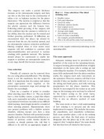
and safely (Figure 2.11). Similarly, an adjustable
diamond tipped cutting calliper can be used
(Figure 2.12). However, a standard blade, pocket
knife, or keratome may be employed. The
anterior chamber should first be filled with a
viscoelastic material in order to reduce the risk of
inadvertent damage to the intraocular structures,
in particular the anterior capsule. The blade is
then introduced into the incision, ensuring that
its edge is parallel to the lateral margins of the
tunnel. Cutting on the inward stroke of the blade
ensures that the sides of the tunnel remain a
consistent length (Figure 2.13a). If the incision is
cut on the outward stroke the tunnel length
shortens (Figure 2.13b), and if a sawing action is
used the wound adopts a zigzag pattern (Figure
2.13c). Placing the blade parallel to the internal
lateral margin of the tunnel avoids creating a
funnel shape and achieves a consistent width.
When converting from phacoemulsification to an
alternative extracapsular technique, an alternative
is to close the initial temporal incision and revert to
a different incision type at the superior meridian.
Several studies have demonstrated that the
initial incision width enlarges during
instrumentation.
32
Scanning electronmicroscopy
has shown tearing of corneal structures following
IOL implantation through small incisions.
33
It
has been suggested that adequate surgical
Figure 2.11 Truncated keratome for incision
enlargement (Edge Ahead IOL knife; BD Ophthalmic
Systems).
Figure 2.12 Pearce single diamond tipped calliper
for wound enlargement (Duckworth and Kent).
c)
b)
a)
Figure 2.13 Wound profile following enlargement is
dependant on direction of blade cut. (a) Correct:
inward, resulting in a consistent tunnel length.
(b) Incorrect: outward, resulting in a shortened tunnel
length. (c) Incorrect: inward and outward, resulting in
a varying tunnel length.
23
INCISION PLANNING AND CONSTRUCTION FOR PHACOEMULSIFICATION
23
enlargement of the primary incision, before IOL
insertion, avoids deformation and lateral tearing
of the wound, preserves incision structure, and
reduces the risk of wound leakage. Enlargement
or stretching of the wound during IOL
implantation has been shown to vary with the
type of lens implant used and, importantly, with
its power.
34
High dioptre power lenses are
usually thicker and therefore require more
wound enlargement before implantation.
Incision closure
Following exchange of viscoelastic for
balanced salt solution (BSS) at the end of
surgery, the anterior chamber should be filled
with BSS via the paracentesis. This allows the
valve-like internal corneal lip of the incision to
close. The security of the incision can then be
examined by gentle pressure on the central
cornea or the limbus. The incision and
paracentesis (or paracenteses) can be dried with
a surgical sponge, and if they are watertight then
they will remain dry. It should be recognised that
substantial pressure on the posterior aspect of
the tunnel may cause leakage and does not
necessarily imply a failure to self-seal.
Corneal hydration can be used to augment
closure of a CCI. BSS in a syringe with a
narrow-gauge blunt cannula is employed. The
cannula tip is placed within the lateral aspect of
the tunnel and directed laterally into the stroma.
BSS is then gently injected to achieve localised
oedema with loss of corneal clarity (Figure 2.14).
A suture may be required to close a wound that
has failed to self-seal or where a phaco burn has
occurred. Both absorbable and non-absorbable
sutures have been employed, although non-
absorbable monofilament is more frequently
used with corneal incisions. In cases where a
large incision may induce astigmatism, a suture
may also be desirable. However, this may delay
stabilisation of postoperative astigmatism as
compared with unsutured incisions.
35
A suture
may be useful to reinforce the wound in patients
who are likely to rub the eye, for example
children or those with mental handicap.
In the past interrupted radial sutures have been
widely employed to close large-incision cataract
extraction wounds. Such sutures appose blocks
of tissue and prevent aqueous leakage; however
if tight they may induce corneal steepening and
“plus” astigmatism. Conversely, loose sutures
may result in corneal flattening and “minus”
astigmatism. Suture techniques to close both
scleral and corneal phacoemulsification incisions
include the simple “X” suture (Figure 2.15), the
Shepard horizontal suture,
4
and the Fine infinity
suture.
36
They aim to oppose the floor and the
roof of the incision and create anteroposterior
wound compression, minimising radial forces on
Figure 2.14 Corneal hydration to close a clear corneal
incision.
Figure 2.15 Detail of a cross (“X”) suture.
the cornea and hence reducing induced
astigmatism.
References
1 Kelman CD. Phacoemulsification and aspiration: a new
technique of cataract removal: a preliminary report. Am
J Ophthalmol 1967;64:23–35.
2 Koch PS. Structural analysis of cataract incision
construction. J Cataract Refract Surg 1991;17(suppl):
661–7.
3 Girard LJ, Rodriguez J, Mailman ML. Reducing
surgically induced astigmatism by using a scleral tunnel.
Am J Ophthalmol 1984;97:450–6.
4 Shepard JR. Induced astigmatism in small incision
cataract surgery. J Cataract Refract Surg 1989;15:85–8.
5 Ernest PH, Lavery KT, Kiessling LA. Is there a
difference in incision healing based on location? J
Cataract Refract Surg 1998;24:482–6.
6 McFarland MS. The clinical history of sutureless
surgery: the first modern sutureless cases. In: Gills JP,
Martin RG, Sanders DR, eds. Sutureless cataract surgery.
Thorofare, NJ: Slack Inc., 1992.
7 Broadway DC, Grierson I, Hitchings RA. Local effects
of previous conjunctival incisional surgery and the
subsequent outcome of filtration surgery. Am J
Ophthalmol 1998;125:805–18.
8 Oshima Y, Tsujikawa K, Oh A, Harino S. Comparative
study of intraocular lens implantation through 3·0 mm
temporal clear corneal and superior scleral tunnel self-
sealing incisions. J Cataract Refract Surg 1997;23:
347–53.
9 Ernest PH, Neuhann T. Posterior limbal incision.
J Cataract Refract Surg 1996;22:78–84.
10 Ernest PH, Lavery KT, Kiessling LA. Relative strength
of scleral corneal and clear corneal incisions constructed
in cadaver eyes. J Cataract Refract Surg 1994;20:626–9.
11 Vass C, Menapace R, Rainer G. Corneal topographic
changes after frown and straight sclerocorneal incisions.
J Cataract Refract Surg 1997;23:913–22.
12 Long DA, Monica ML. A prospective evaluation of
corneal curvature changes with 3·0–3·5mm corneal
tunnel phacoemulsification. Ophthalmology 1996;103:
226–32.
13 Wirbelauer C, Anders N, Pham DT, Wollensak J. Effect
of incision location on preoperative oblique astigmatism
after scleral tunnel incision. J Cataract Refract Surg
1997;23:365–71.
14 Oshika T, Tsuboi S, Yaguchi S, et al. Comparative study
of intraocular lens implantation through 3·2 and 5·5 mm
incisions. Ophthalmology 1994;101:1183–90.
15 Hayashi K, Hayashi HHH, Nakao F, Hayashi F. The
correlation between incision size and corneal shape
changes in sutureless cataract surgery. Ophthalmology
1995;102:550–6.
16 Rainer G, Menapace R, Vass C, Annen D, Strenn K,
Papapanos P. Surgically induced astigmatism following
a 4·0 mm sclerocorneal valve incision. J Cataract Refract
Surg 1997;23:358–64.
17 Roman S, Auclin F, Chong-Sit DA, Ullern MM.
Surgically induced astigmatism with superior and
temporal incisions in cases of with-the-rule preoperative
astigmatism. J Cataract Refract Surg 1998;24:1636–41.
18 Rainer G, Menapace R, Vass C, Annen D, Findl O,
Schmetter K. Corneal shape changes after temporal and
superolateral 3·0 mm clear corneal incisions. J Cataract
Refract Surg 1999;25:1121–6.
19 Guyton D. Prescribing cylinders: the problem of
disortion. Surv Ophthalmol 1997;22:177–88.
20 Bear JC, Richler A. Cylindrical refractive error: a
population study in Western Newfoundland. Am J
Optom Physiol Opt 1983;60:39–45.
21 Hirsch MJ. Changes in astigmatism during the first eight
years of school. Am J Optom 1963;40:127–32.
22 Ravalico G, Parentin F, Baccara F. Effect of astigmatism
on multifocal intraocular lenses. J Cataract Refract
Surgery 1999;25:804–7.
23 Langerman DW. Architectural design of a self-sealing
corneal tunnel, single-hinge incision. J Cataract Refract
Surg 1994;20:84–8.
24 Amigo A, Giebel AW, Muinos JA. Astigmatic
keratotomy effect of single-hinge, clear corneal incisions
using various preincision lengths. J Cataract Refract Surg
1998;24:765–71.
25 Budak K, Friedman NJ, Koch D. Limbal relaxing
incisions with cataract surgery. J Cataract Refract Surg
1998;24:503–8.
26 Lever JL. Dahan E. Opposite clear corneal incisions.
J Cataract Refract Surg 200;26:803–5
27 Nichamin LD. Opposite clear corneal incisions.
J Cataract Refract Surg 2001;27:7–8.
28 Leyland M, Zinicola E, Bloom P, Lee N. Prospective
evaluation of a plate haptic toric intraocular lens. Eye
2001;15:202–5.
29 Patel CK, Ormonde S, Rosen PH, Bron AJ.
Postoperative intraocular lens rotation: a randomized
comparison of plate and loop haptic implants.
Ophthalmology 1999;106:2190–5.
30 Allan BD. Mechanism of iris prolapse: a qualitative
analysis and implications for surgical technique.
J Cataract Refract Surg 1995;21:182–6.
31 Radner W, Menapace R, Zehetmayer M, Mallinger R.
Ultrastructure of clear corneal incisions. Part I: effect of
keratomes and incision width on corneal trauma after
lens implantation. J Cataract Refract Surg 1998;24:
487–92.
32 Steinert RF, Deacon J. Enlargement of incision width
during phacoemulsification and folded intraocular lens
implant surgery. Ophthalmology 1996;103:220–5.
33 Kohnen T, Koch DD. Experimental and clinical
evaluation of incision size and shape following forceps
and injector implantation of a three-piece high-
refractive-index silicone intraocular lens. Graefes Arch
Clin Exp Ophthalmol 1998;236:922–8.
34 Moreno-Montanes J, Maldonado MJ, Garcia-Layana A,
Aliseda D, Munuera JM. Final clear corneal incision size
for AcrySof intraocular lenses. J Cataract Refract Surg
1999;25:959–63.
35 Lyhne N, Corydon L. Two year follow-up of
astigmatism after phacoemulsification with adjusted and
unadjusted sutured versus sutureless 5·2mm superior
scleral tunnels. J Cataract Refract Surg 1998;24:
1647–51.
36 Fine IH. Infinity suture: modified horizontal suture for
6·5mm incisions. In: Gills JP, Sanders DR, eds. Small
incision cataract surgery: foldable lenses, one-stitch surgery,
sutureless surgery, astigmatic keratotomy. Thorofare, NJ:
Slack Inc., 1990.
CATARACT SURGERY
24
Capsulorhexis is not just a neat way to open the
anterior capsule. It is fundamentally different from
all previous techniques in that it maintains the
mechanical and structural integrity of the capsular
bag. It has therefore become the universally
accepted standard method of opening the anterior
capsule for the purpose of cataract extraction
(Box 3.1). The continuous smooth edge to the
capsulotomy provides a much greater degree of
strength,
1
and as such it has contributed
significantly to the development of today’s safe
and controllable phacoemulsification techniques.
Moreover, it has made possible precise,
reproducible, and permanent intracapsular
fixation of the intraocular lens (IOL).
2
In the past, the opening of the anterior lens
capsule for the purpose of removing the cataract
using an extracapsular technique was relatively
uncontrolled. Toothed forceps were used to
remove whatever could be grasped or a needle
would be employed to create a slit opening in the
anterior capsule. With the advent of modern
extracapsular techniques better and more
controlled anterior capsulotomy techniques
were needed to aid manipulation of the nucleus
and aspiration of cortex. The “can opener” and
the “letter box” endocapsular techniques
became the most widely used (see Chapter 8).
The need for even better control arose with the
realisation that the IOL should ideally remain in
a physiological position within the capsular bag
and that ragged peripheral radial tears in the
capsulectomy margin can allow one or both
haptics to dislodge out of the bag. Capsulorhexis
was developed to solve this problem. In 1984,
simultaneously and independently, Howard
Gimbel and Thomas Neuhann described the
same technique, namely tearing a circular
opening in the anterior capsule, instead of
cutting or ripping the capsule, to obtain an
aperture with a smooth continuous margin. The
technique was demonstrated in 1985 in the form
of video presentations, and the first formal
publication was in 1987.
3
The new term
“capsulorhexis” (capsule tearing) was proposed
by Thomas Neuhann in order to emphasise the
25
3 Capsulorhexis
Box 3.1 Advantages of capsulorhexis
• No loose tags or jagged flaps of anterior
capsule to interfere with surgery (especially
during the aspiration of cortical remnants)
• Forces exerted on the capsule and the zonules
are minimal
• The anterior capsule remains stretched
horizontally, maintaining the intracapsular
space for surgical manoeuvres
• Radial tears cannot occur with an intact
capsulorhexis
• Secure, verifiable, reproducible, and
permanent intracapsular implantation and
fixation of lens implants
• Secure intraocular lens implantation into the
ciliary sulcus in the event of a posterior
capsular rupture
• It can be learned safely, without exposing the
patient to any risk, during a standard
extracapsular procedure
novel nature of the technique. Howard Gimbel
originally termed his technique “continuous tear
capsulotomy”. By bringing together both terms,
the abbreviation “CCC” for “continuous
curvilinear capsulorhexis” evolved.
Surgical technique
The technique of capsulorhexis is based on the
property of the anterior lens capsule to behave
mechanically like cellophane. Whereas tearing
from a smooth edge is very difficult, tearing
occurs readily with a minimal amount of force
when departing from a linear break. Following
an incision in the capsule, tractional forces are
applied using either a needle or forceps to
propagate the rhexis tear. Stretching forces,
applied perpendicular to the desired direction of
the tear, will cause tearing but this may be
sudden and uncontrolled (Figure 3.1a). Shear
forces are applied in the direction of tear and are
preferable because the tear direction and rate are
more controllable (Figure 3.1b). In practice a
combination of stretch and shear is used to steer
the tear. An inward or centripetal vector is
required to direct the tear centrally (Figure 3.2c),
whereas an outward or radial vector is applied to
tear in the opposite direction (Figure 3.2d). The
more distant the point of engagement is from the
leading edge of the tear, the more difficult it is to
control the tear and the more centripetally it
must be torn. In contrast, the closer the point of
engagement is to the leading edge, the more
directly the tear will follow the direction of
traction (Figure 3.3). It is therefore advisable to
regrasp the flap close to the leading edge of
the tear frequently (a basic principle governing
the entire technique and its variations). The
intrinsic forces on the anterior capsule are
largely determined by the tension of the zonules.
Shallowing of the anterior chamber and forward
movement of the lens–iris diaphragm causes a
change in the normal vector forces, making it
CATARACT SURGERY
26
a) b)
Figure 3.1 Comparison between tear propagation by
shear and stretch forces illustrated using a sheet of A4
paper (try it for yourself). (a) Stretch: uncontrolled.
(b) Shear: controlled.
a)
c)
b)
d)
r
Figure 3.2 Capsulorhexis. (a) Initiating the
capsulorhexis: central anterior capsule puncture is
extended radially. Note: length r determines the
radius (and hence diameter) of the rhexis.
(b) Flapping over the tearing edge to facilitate shear
tearing. (c) Steering the tear: centripetal vector (solid
arrow) = tear directed inward (open arrow),
decreasing rhexis diameter. (d) Steering the tear:
radial vector (solid arrow) = tear directed outward
(open arrow), increasing rhexis diameter.
more difficult to keep the tear from irretrievably
running outward. Maintaining a deep anterior
chamber during capsulorhexis is therefore
essential, irrespective of the technique used.
There are three basic choices a surgeon has to
make at the outset:
• The instrument used: a cystotome needle or
capsulorhexis forceps
• The access: via the main incision or via a side
port (paracentesis)
• The medium: irrigation with fluid, viscoelastic,
or air.
These three options may be variously
combined, for example using a cystotome
through a side paracentesis under fluid
irrigation, or forceps through the main incision
using viscoelastic. Whichever technique (of the
countless variations that have been described)
the individual surgeon comes to prefer is not
important. What is important is that the surgeon
understands the basic underlying principle and
adapts it to their individual surgical technique.
4
Capsulorhexis is not a technique in the sense of
a cookbook recipe; it is really a principle that
everybody can make work their own way. In that
sense, the descriptions below are to be
understood as “basic directions” rather than
strict prescriptions.
Needle technique
Either a needle specifically designed for
capsulorhexis is used or a 23-gauge needle may
be bent to about 90° near the hub and its tip
bent 45° away from the bevel (Figure 3.4). If
viscoelastic is not used then the needle can be
mounted on an infusion hand piece connected
to a gravity-fed infusion at its maximum height.
With the infusion continuously running, the
anterior chamber is entered through the side
port, the size of which should just permit passage
of the needle. The chamber is therefore fully
formed and maintained as deep as possible.
When using viscoelastic it may be necessary to
refill the anterior chamber during the rhexis, and
by mounting the needle on the viscoelastic
syringe this can be achieved without removing
the needle from the eye (Figure 3.4).
5
The anterior capsule is first perforated near
its geometric centre with the needle tip, which is
advanced to one side (right or left, depending on
surgeon preference) to create a small curved
incision in the capsule (Figure 3.2a). The
desired radius of curvature (or diameter) of the
rhexis is determined by the magnitude of this
sideways movement. When this is reached, the
capsule is lifted close to the leading edge of the
CAPSULORHEXIS
27
Figure 3.3 Controlling the tear. (a) Grasping away
from the tearing edge reduces control. (b) Grasping
near the tearing edge maximises control.
a)
b)
incision and pushed (or pulled) upward in order
to commence the tear. This lifting movement
creates a small flap that is turned or flipped over
on itself (Figure 3.2b). The rhexis tear is then
propagated by engaging this capsule flap with
the tip of the needle (i.e. engaging the side that
had originally been in contact with the cortex
but is now reflected back). Sufficient pressure is
used to grip the flap without the needle tip
perforating the capsule or disturbing the
underlying cortex. (This is particularly important
because disturbing the cortex can severely
reduce visualisation of the flap and tear.) Having
engaged the capsular flap, it is torn in a circular
fashion using appropriately directed tear vectors.
When brought around full circle, the tear is
blended into itself from outside in to avoid a
discontinuity. This inward spiralling manoeuvre,
in which the final part of the rhexis is made to
overlap the origin, to ensures that the rhexis
forms a (near) perfect circle (Figure 3.5). If this
is not carried out then a small triangular peak
results that might interfere with subsequent
elements of the phacoemulsification procedure.
When using viscoelastic to maintain the
anterior chamber it is important to ensure that,
as the capsular flap increases in size, the flap is
kept reflected or spread out over its undersurface
so that the torn edge is clearly identifiable.
Disregarding this detail can lead to an irregular
flap that is frozen in viscoelastic and possibly
mixed with disrupted cortex, making
identification of the tear edge difficult and
leading to loss of control of the rhexis.
Forceps technique
When using a forceps technique for
capsulorhexis a viscoelastic substance is typically
used to maintain the anterior chamber, although
an infusion with an anterior chamber maintainer
may be used as an alternative. Forceps of the
Utrata type (Figure 3.6a) require access through
the main incision (approximately 3 mm in width)
whereas vitrectomy-type forceps (Figure 3.6b),
such as the Koch forceps, may be used through
a paracentesis. To commence the forceps
technique a small central puncture is first made
in the anterior capsule, either with a needle or tip
of the forceps. Some forceps are available with
sharpened tips that are specifically designed for
this purpose.
6
Capsulorhexis using forceps allows the
capsule to be grasped directly and has the
advantage of making the technique more
controllable for many surgeons. The forceps
CATARACT SURGERY
28
Figure 3.4 Capsulorhexis needles. Insulin syringe
needle bent to act as a cystotome (top). Manufactured
cystotome (BD Ophthalmic Systems) mounted on a
viscoelastic syringe (bottom).
Figure 3.5 Completed capsulorhexis. Note that, by
overlapping the start and finish points, it is completely
circular and that the cortex is undisturbed.
technique carries the disadvantage that as the
rhexis proceeds, especially beneath the incision,
deformation of the wound makes the loss of
viscoelastic inevitable. As discussed previously,
it is crucial to maintain a deep anterior chamber
during capsulorhexis. Refilling the chamber with
viscoelastic as loss occurs minimises the risk of
loss of control over the capsule tear but is time
consuming. Using instruments that open only
at the tip (cross-action or vitrectomy-type
capsulorhexis forceps) and that may be used
through a paracentesis can help to tackle this
problem.
Optimal diameter
The question of which diameter should ideally
be attempted is best answered with respect to
the size of the lens implant optic. Most surgeons
prefer a diameter that will just cover the margin
of the optical part of the IOL, completely sealing
it into the capsular bag, which reduces posterior
capsule opacification (see Chapter 12). There is
no doubt that an asymmetrical opening, partly
covering and partly not covering the optic
margin, is to be avoided because for its potential
of causing IOL decentration.
Learning capsulorhexis
A major advantage of capsulorhexis is that a
surgeon familiar with extracapsular sugery can
learn it without exposing the patient to
additional risk. Whatever technique of anterior
capsulotomy the surgeon normally uses, a
capsulorhexis may first be attempted using the
guidelines above. The key rule to follow is
not to persist when control of the tear is lost.
From this moment, the surgeon should continue
by reverting to their standard capsulotomy
technique. Therefore, during the learning period
the patient, as well as the surgeon, will at least
benefit from the surgeon’s basic technique. For
the new surgeon, artificial and animal eyes allow
the capsulorhexis technique to be practised
safely (see Chapter 1). Staining the capsule as
discussed below can help the trainee during the
early stages of learning to perform a rhexis.
7
Complications: avoidance and
management
There are three key intraoperative complications
that can occur during capsulorhexis:
• A discontinuity of the capsule margin
• A tear into the zonules
• A diameter that is too small.
CAPSULORHEXIS
29
Figure 3.6 Capsule forceps with close-ups of tips.
(a) Utrata-type forceps for use through main incision
(Duckworth and Kent). (b) Vitrectomy-type forceps
for use through a paracentesis (Duckworth and Kent).
b)
a)
The causes, prevention, and management for
each of these situations are discussed here. The
two commonest postoperative complications
following capsulorhexis are anterior capsule
contraction and incarceration of viscoelastic,
which are discussed in Chapter 7.
Discontinuity of the anterior
capsule margin
The major causes of a discontinuity in the
rhexis are finishing the capsulorhexis from inside
outward or cutting an intact rhexis margin with
the second instrument or the phaco tip during
surgery. The most important rule when
completing the capsulorhexis is always to close
the circle from outside inward. If the flap breaks
off during the course of the tear then the
remaining flap created by the initial incision in
the capsule can sometimes be used to complete
the rhexis by going in the opposite direction (for
example, clockwise instead of anticlockwise). If
this is not possible then a deliberate incision at a
separate site in the rhexis edge may be torn
round to include the discontinuity (Figure 3.7).
This can also be useful if the tear runs out
during capsulorhexis. A break in the rhexis that
is recognised during surgery should, if possible,
be grasped with forceps and torn round to blend
it into the main rhexis edge.
A break in an otherwise intact rhexis margin
will in most cases cause a radial tear into the
zonules. The risk of a radial tear extending
around into the posterior capsule increases with
friability of the zonules and manoeuvres that
distend the anterior capsule opening. Nuclear
fracturing techniques, which rely on pushing
the nuclear parts widely apart, and IOL
implantation must therefore proceed with
caution. A radial tear in the rhexis margin is a
contraindication to plate haptic lens implantation
but it does not necessarily preclude the use of
other folding IOL implants. The IOL should be
carefully inserted and the haptics placed at 90°
from the radial tear (a relaxing incision opposite
the first tear may be considered).
Tear into the zonules
If the tear involves zonular fibres, either because
it is too peripheral or because the zonules insert
abnormally centrally, then it cannot easily be
CATARACT SURGERY
30
a)
b)
Figure 3.7 Blending a break in the capsulorhexis
margin into main rhexis. (a) Gripping the tear with
capsule forceps. (b) Resulting complete but
asymmetrical rhexis.
continued. Persistent attempts to retrieve the
rhexis may simply direct the tear along the
zonule fibre into the periphery, like tearing paper
alongside a ruler. With the help of high
microscope magnification, careful focusing, and
an optimised red or specular reflex, the relevant
zonules may usually be identified and their
insertions carefully removed from the capsule
with a needle or forceps. The tear can then be
directed centrally and continued. Sometimes
this situation can also be managed by grasping
the flap close to its tearing edge and briskly
pulling it centrally. However, this manoeuvre
carries a higher risk and is only advised when the
more controlled approach does not seem
possible.
Capsulorhexis with too small a diameter
If the surgeon realises that the diameter of the
rhexis is getting smaller than desired, then the
tear may be continued beyond 360° in an
outward spiral until the desired diameter is
reached. Alternatively, the diameter may be
secondarily enlarged after phacoemulsification,
as described below for the mini-capsulorhexis
technique.
Difficult situations (troubleshooting)
Capsulorhexis is usually comparatively
straightforward to perform under ideal
conditions. When these conditions are not met
capsulorhexis becomes more difficult but should
not be unmanageable.
There are several difficult situations. Although
these frequently occur in various combinations,
they are discussed separately in order to make
the basic principles of management clear. In
all cases maintaining control of the capsule
tear is essential. It is important that the anterior
chamber be maintained as deep as possible,
and the rhexis should progress slowly in small
steps with frequent regrasping near the tearing
edge.
No red reflex
When there is an inadequate reflex from the
fundus to retroilluminate the surgical site, other
clues and techniques can be used to visualise the
capsule. First, slightly inclining the eye relative to
the observation and illumination paths can
sometimes produce enough of a red reflex to
proceed safely. Increasing the microscope
magnification is also often helpful. Oblique
illumination, either in addition to or instead of
coaxial illumination, can provide an “orange skin”
like specular reflex on the capsule. Having
switches on the microscope control pedal allows
the two illumination types to be used to maximum
effect. Alternatively, a vitrectomy endoilluminator,
used through a paracentesis, can produce effective
oblique illumination.
8
In the UK Mr Arthur Steele
popularised capsulorhexis under air using a needle
in a closed chamber when no red reflex is present.
More recently capsule stains have been used to
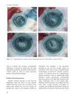
improve visualisation of the capsule (Figure 3.8).
Fluorescein,
9
indocyanine green,
10
and trypan
blue
11
have all been described, either injected
directly intracamerally or under the capsule.
Intracameral injection is usually preceded by
injecting an air bubble into the anterior
chamber, and the air and dye is then displaced
by viscoelastic.
12
Capsule visualisation with
fluorescein staining is improved by using a blue
light source.
The small pupil
In addition to obscuring the anterior capsule,
a small pupil may also reduce the red reflex.
Therefore, the techniques described above may
be needed. Measures to increase the pupil
diameter are discussed in Chapter 10.
Alternatively, the pupil can be retracted with a
second instrument through a paracentesis,
allowing the peripheral capsule to be viewed and
the rhexis performed. As the tear progresses the
second instrument is moved along the pupillary
edge to maintain visualisation. Pulling the tear
around behind the iris without seeing the tearing
CAPSULORHEXIS
31