Adaptive Motion of Animals and Machines - Hiroshi Kimura et al (Eds) Part 5 pdf
Bạn đang xem bản rút gọn của tài liệu. Xem và tải ngay bản đầy đủ của tài liệu tại đây (533.07 KB, 20 trang )
76 R. Hackert, H. Witte, M. S. Fischer
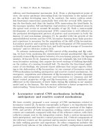
Fig. 7. Variations of the angle ulna/ground with speed are small. The right scale
gives the number of steps N used to calculate the mean values and the standard
deviations.
[12]. In humans the spring-leg and the mass (CoM) are well aligned. The
above described results indicate, that the common linear spring-point mass
model may as well be applied to the situation in the pika’s forelimbs. In
the hindlimbs, the consideration of the mass extension of the trunk seems
inevitable. The variation of the CoM height found in this study is very similar
to that for the dog derived from numerical integration of ground reaction
forces by Cavagna et al. [7]. In that case the vertical displacement of the CoM
over time showed more than two extrema. McMahon & Cheng [13] calculated
how the angle of attack of a spring-mass system defined as the angle which
minimized the maximum of the force during the stance phase variates as a
function of the horizontal and vertical velocity. The variation of this angle
with horizontal velocity also is small (about 7˚). The reasons for an almost
constancy of this angle still are poorly understood as far as the dynamics of
locomotion is concerned, but perhaps may find an explanation by the results
of further studies on the dynamic stability of quadrupedal locomotion.
Our study shows that the motion of the trunk is a determinant factor in
the motion of the CoM. The model of a rigid body that jumps from one limb
to the other is not able to explain the variety of the pattern of vertical motions
of CoM provoked by running locomotor modes. Bending of the back is not a
passive bending due to inertia of the back. For robotics the Raibert idea of
minimizing dissipative energy flows in combination with the usage of “intelli-
gent“, self-stabilising mechanics with minimal neuronal/computational con-
trol effort is attractive. Understanding of motion systems evolutively tested
for longer periods in this context may be a promising directive.
Interactions between Motions of the Trunk and the Angle of Attack 77
Acknowledgments
We thank Prof. R. Blickhan, who kindly provided us access to the high speed
camera system. Dr. D. Haarhaus invested his ecxperience in a multitude of
cineradiographic experiments.
References
1. Hildebrand M.(1965): Symmetrical gaits of horses. – Science 150: 701-708.
2. Hildebrand M.(1977): Analysis of asymmetrical gaits. –JMamm58(2 ): 131-156.
3. Jenkins F.A.(1971): Limb posture and locomotion in the Virginia opossum
(Didelphis marsupialis) and other non-cursorial mammals. J Zool (Lond) 165:
303-315.
4. Fischer M.S. & Lehmann R.(1998): Application of cineradiography for the metric
and kinematic study of in-phase gaits during locomotion of the pika (Ochotona
rufescens, Mammalia: Lagomorpha). - Zoology 101: 12-37.
5. MS Fischer & H Witte (1998): The functional morphology of the three-
segmented limb of mammals and its specialities in small and medium-sized
mammals. Proc Europ Mechanics Coll Euromech 375 Biology and Technology
of Walking: 10–17.
6. Cavagna G.A., Saibene & Margaria (1964) Mechanical work in running - J Appl
Physiol 19(2) 249-256.
7. Cavagna G.A., Heglund N.C. & Taylor C.R. (1977): Mechanical work in terres-
trial locomotion: two basic mechanisms for minimizing energy expenditure. - Am
J Physiol 233: 243-2.
8. McMahon T.A.(1985): The role of compliance in mammalian running gaits. -J
exp Biol 115: 263-282.
9. Bernstein N.A.(1967): The coordination and regulation of movements. Perga-
mon, London.
10. Blickhan R.(1989): The spring-mass model for running and hopping. - J
Biomech 22(11/12): 1217-1227.
11. Lee C.R., Farley C. (1998): Determinant of the center of mass in human walking
and running. - JexpBiol201(pt 21): 2935-2944.
12. Full R.J., Koditschek D.E.(1999): Templates and anchors: neuromechanical hy-
potheses of legged locomotion on land. – JexpBiol202(Pt 23), 3325–3332.
13. McMahon T.A. & Cheng G.C. (1990): The mechanics of running: how does
stiffness couple with speed? – JBiomech23 (Suppl. 1): 65-78.
On the Dynamics of Bounding and Extensions:
Towards the Half-Bound and Gallop Gaits
Ioannis Poulakakis, James Andrew Smith, and Martin Buehler
Ambulatory Robotics Laboratory, Centre for Intelligent Machines,
McGill University, Montr´eal QC H3A 2A7, Canada
Abstract. This paper examines how simple control laws stabilize complex running
behaviors such as bounding. First, we discuss the unexpectedly different local and
global forward speed versus touchdown angle relationships in the self-stabilized
Spring Loaded Inverted Pendulum. Then we show that, even for a more complex
energy conserving unactuated quadrupedal model, many bounding motions exist,
which can be locally open loop stable! The success of simple bounding controllers
motivated the use of similar control laws for asymmetric gaits resulting in the first
experimental implementations of the half-bound and the rotary gallop on Scout II.
1 Introduction
Many mobile robotic applications might benefit from the improved mobil-
ity and versatility of legs. Twenty years ago, Raibert set the stage with his
groundbreaking work on dynamically stable legged robots by introducing a
simple and highly effective three-part controller for stabilizing running on
his one-, two-, and four-legged robots, [9]. Other research showed that even
simpler control laws, which do not require task level or body state feedback,
can stabilize running as well, [1]. Previous work on the Scout II quadruped
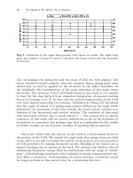
(Fig. 1) showed that open loop control laws simply positioning the legs at a
desired touchdown angle, result in stable running at speeds over 1 m/s, [12].
Fig. 1. Scout II: A simple four-legged robot.
Motivated by experiments on cockroaches (death-head cockroach, Blaber-
ous discoidalis), Kubow and Full studied the role of the mechanical sys-
tem in control by developing a simple two-dimensional hexapedal model, [5].
The model included no equivalent of nervous feedback and it was found to
80 I. Poulakakis, J. A. Smith, M. Buehler
be inherently stable. This work first revealed the significance of mechanical
feedback in simplifying neural control. Full and Koditschek set a foundation
for a systematic study of legged locomotion by introducing the concepts of
templates and anchors, [2]. To study the basic properties of sagittal plane
running, the Spring Loaded Inverted Pendulum (SLIP) template has been
proposed, which describes running in animals that differ in skeletal type, leg
number and posture, [2]. Seyfarth et al., [11], and Ghigliazza et al., [3], found
that for certain leg touchdown angles, the SLIP becomes self-stabilized if the
leg stiffness is properly adjusted and a minimum running speed is exceeded.
In this paper, we first describe some interesting aspects of the relation-
ship between forward speed and leg touchdown angles in the self-stabilized
SLIP. Next, we attempt to provide an explanation for simple control laws
being adequate in stabilizing complex tasks such as bounding, based on a
simple sagittal “template” model. Passively generated cyclic bounding mo-
tions are identified and a regime where the system is self-stabilized is also
found. Furthermore, motivated by the success of simple control laws to gen-
erating bounding running, we extended the bounding controller presented in
[12] to allow for asymmetric three- and four-beat gaits. The half-bound, [4],
and the rotary gallop [4,10], expand our robots’ gait repertoire, by introduc-
ing an asymmetry to the bound, in the form of the leading and trailing legs.
To the authors’ best knowledge this is the first implementation of both the
half-bound and the gallop in a robot.
2 Bounding experiments with Scout II
Scout II (Fig. 1) has been designed for power-autonomous operation. One of
its most important features is that it uses a single actuator per leg. Thus,
each leg has two degrees of freedom (DOF): the actuated revolute hip DOF,
and the passive linear compliant leg DOF.
In the bound gait the essential components of the motion take place in
the sagittal plane. In [12] we propose a controller, which results in fast and
robust bounding running with forward speeds up to 1.3 m/s, without body
state feedback. The controller is based on two individual, independent front
and back virtual leg controllers. The front and back virtual legs each detect
two leg states - stance and flight. During flight, the controller servoes the
flight leg to a desired, fixed, touchdown angle. During stance the leg is swept
back with a constant commanded torque until a sweep limit is reached. Note
that the actual applied torque during stance is determined primarily by the
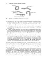
motor’s torque-speed limits, [12]. The sequence of the phases of the resulting
bounding gait is given in Fig. 2.
Scout II is an underactuated, highly nonlinear, intermittent dynamic sys-
tem. The limited ability in applying hip torques due to actuator and friction
constraints and due to unilateral ground forces further increases the complex-
ity. Furthermore, as Full and Koditschek state in [2], “locomotion results from
On the Dynamics of Bounding and Extensions 81
complex high-dimensional, dynamically coupled interaction between an or-
ganism and its environment”. Thus, the task itself is complex too, and cannot
be specified via reference trajectories. Despite this complexity, simple control
laws, like the one described above and in [12], can stabilize periodic motions,
resulting in robust and fast running without requiring any task level feedback
like forward velocity. Moreover, they do not require body state feedback.
Fig. 2. Bounding phases and events.
It is therefore natural to ask why such a complex system can accomplish
such a complex task without intense control action. As outlined in this paper,
and in more detail in [7,8], a possible answer is that Scout II’s unactuated,
conservative dynamics already exhibit stable bounding cycles, and hence a
simple controller is all that is needed for keeping the robot bounding.
3 Self-stabilization in the SLIP
The existence of passivelly stable gaits in the conservative, unactuated SLIP,
discussed in [3,11], is a celebrated result that suggests the significance of the
mechanical system in control as was first pointed out by Kubow and Full in
[5]. However, the mechanism that results in self-stabilization is not yet fully
understood, at least in a way that could immediately be applicable to improve
existing control algorithms. It is known that for a set of initial conditions
(forward speed and apex height), there exists a touchdown angle at which
the system maintains its initial forward speed, see Fig. 3 (left). As Raibert
noticed, [9], if these conditions are perturbed, for example, by decreasing the
touchdown angle, then the system will accelerate in the first step, and, if the
touchdown angle is kept constant, it will also accelerate in the subsequent
steps and finally fall due to toe stubbing. However, when the parameters are
within the self-stabilization regime, the system does not fall! It converges to
a periodic motion with symmetric stance phases and higher forward speeds.
This fact is not captured in Raibert’s linear steady-state argument, [9], based
on which one would be unable to predict self-stabilization of the system.
A question we address next is what is the relationship between the forward
speed at which the system converges i.e. the speed at convergence, and the
touchdown angle. To this end, simulation runs have been performed in which
82 I. Poulakakis, J. A. Smith, M. Buehler
the initial apex height and initial forward velocity are fixed, thus the energy
level is fixed, while the touchdown angle changes in a range where cyclic
motion is achieved. For a given energy level, this results in a curve relating the
speed at convergence to the touchdown angle. Subsequently, the apex height
is kept constant, while the initial forward velocity varies between 5 and 7 m/s.
This results in a family of constant energy curves, which are plotted in Fig.
3 (right). It is interesting to see in Fig. 3 that in the self-stabilizing regime
of the SLIP, an increase in the touchdown angle at constant energy results in
a lower forward speed at convergence. This means that higher steady state
forward speeds can be accommodated by smaller touchdown angles, which,
at first glance, is not in agreement with the global behavior that higher speeds
require bigger (flatter) touchdown angles and is evident in Fig. 3 (right).
Fig. 3. Left: Symmetric stance phase in the SLIP. Right: Forward speed at conver-
gence versus touchdown angle at fixed points obtained for initial forward speeds 5
to 7 m/s and apex height equal to 1 m (l
0
=1 m, k =20 kN/m and m =1 kg).
The fact that globally fixed points at higher speeds require greater (flatter)
touchdown angles was reported by Raibert and it was used to control the
speed of his robots based on a feedback control law, [9]. However, Fig. 3 (right)
suggests that in the absence of control and for constant energy, reducing the
touchdown angle results in an increase of the speed at convergence. Thus,
one must be careful not to transfer results from systems actively stabilized to
passive systems, because otherwise opposite outcomes from those expected
may result. Note also that there might exist parameter values resulting in a
local behavior opposite to that in Fig. 3, illustrating that direct application
of the above results in designing intuitive controllers is not trivial.
4 Modeling the Bounding Gait
In this section the passive dynamics of Scout II in bounding is studied based
on the template model shown in Fig. 4 and conditions allowing steady state
cyclic motion are determined.
On the Dynamics of Bounding and Extensions 83
Assuming that the legs are massless and treating toes in contact with the
ground as frictionless pin joints, the equations of motion for each phase are
d
dt
q
˙q
=
˙q
−M
−1
(F
el
+ G)
, (1)
where q =[xyθ]
T
(Fig. 4), M, is the mass matrix and F
el
, G are the vectors
of the elastic and gravitational forces, respectively. The transition conditions
between phases corresponding to touchdown and lift-off events are
y ± L sin θ ≤ l
0
cos γ
td
i
,l
i
≤ l
0
, (2)
where i = b, f for the back (- in (2)) and front (+ in (2)) leg respectively.
Fig. 4. A template for studying sagittal plane running.
To study the bounding cycle of Fig. 2 a return map is defined using the
apex height in the double leg flight phase as a reference point. The states at
the n
th
apex height constitute the initial conditions for the cycle, based on
which we integrate successively the dynamic equations of all the phases. This
process yields the state vector at the (n+1)
th
apex height, which is the value
of the return map P :
4
×
2
→
4
calculated at the n
th
apex height, i.e.
x
n+1
= P(x
n
, u
n
), (3)
with x =[yθ ˙x
˙
θ]
T
, u =[γ
td
b
γ
td
f
]
T
; the touchdown angles are control inputs.
We seek conditions that result in cyclic motion and correspond to fixed
points ¯x of P, which can be determined by solving x − P(x)=0 for all
the (experimentally) reasonable touchdown angles. The search space is 4-
dimensional with two free parameters and the search is conducted using the
Newton-Raphson method. An initial guess, x
0
n
, for a fixed point is updated
by
x
k+1
n
= x
k
n
+
I −∇P
x
k
n
−1
P
x
k
n
− x
k
n
, (4)
where n corresponds to the n
th
apex height and k to the number of iterations.
Evaluation of (4) until convergence (the error between x
k
n
and x
k+1
n
is
smaller than 1e−6) yields the solution. To calculate P at x
k
n
, we numerically
integrate (1) for each phase using the adaptive step Dormand-Price method
with 1e − 6and1e − 7 relative and absolute tolerances, respectively.
84 I. Poulakakis, J. A. Smith, M. Buehler
Implementation of (4) resulted in a large number of fixed points of P,
for different initial guesses and touchdown angles, which exhibited some very
useful properties, [7,8]. For instance, the pitch angle was found to be always
zero at the apex height. More importantly, the following condition was found
to be true for all the fixed points calculated randomly using (4)
γ
td
f
= −γ
lo
b
,γ
td
b
= −γ
lo
f
. (5)
It is important to mention that this property resembles the case of the SLIP,
in which the condition for fixed points is the lift-off angle to be equal to the
negative of the touchdown angle (symmetric stance phase), [3].
It is desired to find fixed points at specific forward speeds and apex
heights. Therefore, the search scheme described above is modified so that
the forward speed and apex height become its input parameters, specified
according to running requirements, while the touchdown angles are now con-
sidered to be “states” of the search procedure, i.e. variables to be determined
from it, [7,8]. Thus, the search space states and the “inputs” to the search
scheme are x
∗
=[θ
˙
θγ
td
b
γ
td
f
]
T
and u
∗
=[y ˙x]
T
, respectively.
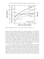
Fig. 5 illustrates that for 1 m/s forward speed, 0.35 m apex height and
varying pitch rate there is a continuum of fixed points, which follows an “eye”
pattern accompanied by two external branches. The existence of the external
branch implies that there is a range of pitch rates where two different fixed
points exist for the same forward speed, apex height and pitch rate. This
is surprising since the same total energy and the same distribution of that
energy among the three modes of the motion -forward, vertical and pitch-
can result in two different motions depending on the touchdown angles. Fixed
points that lie on the internal branch correspond to a bounding motion where
the front leg is brought in front of the torso, while fixed points that lie on
the external branch correspond to a motion where the front leg is brought
towards the torso’s Center of Mass (COM), see Fig. 5 (right).
Fig. 5. Left: Fixed points for 1m/s forward speed and 0.35 m apex height. Right:
Snapshots showing the corresponding motions.
On the Dynamics of Bounding and Extensions 85
5 Local stability of passive bounding
The fact that bounding cycles can be generated passively as a response to the
appropriate initial conditions may have significant implications for control.
Indeed, if the system remains close to its passive behavior, then the actuators
have less work to do to maintain the motion and energy efficiency, an impor-
tant issue to any mobile robot, is improved. Most importantly there might
exist operating regimes where the system is passively stable, thus active sta-
bilization will require less control effort and sensing. The local stability of
the fixed points found in the previous section is now examined. A periodic
solution corresponding to a fixed point ¯x is stable if all the eigenvalues of the
matrix A = ∂P(x, u)/∂x|
x=¯x
have magnitude less than one.
Fig. 6 (left) shows the eigenvalues of A for forward speed 1 m/s, apex
height 0.35 m and varying pitch rate,
˙
θ. The four eigenvalues start at dark
reqions (small
˙
θ), move along the directions of the arrows and converge to the
points marked with “x” located in the brighter regions (large
˙
θ)oftheroot
locus. One of the eigenvalues (#1) is always located at one, reflecting the
conservative nature of the system. Two of the eigenvalues (#2 and #3) start
on the real axis and as
˙
θ increases they move towards each other, they meet
inside the unit circle and then move towards its rim. The fourth eigenvalue
(#4) starts at a high value and moves towards the unit circle but it never
gets into it, for those specific values of forward speed and apex height. Thus,
the system cannot be passively stable for these parameter values.
To illustrate how the forward speed affects stability we present Fig. 6
(right), which shows the magnitude of the larger eigenvalue (#4) at two dif-
ferent forward speeds. For sufficiently high forward speeds and pitch rates,
the larger eigenvalue enters the unit circle while the other eigenvalues remain
well behaved. Therefore, there exists a regime where the system can be pas-
sively stable. This is a very important result since it shows that the system
can tolerate perturbations of the nominal conditions without any control ac-
tion taken! This fact could provide a possible explanation to why Scout II can
bound without the need of complex state feedback controllers. It is important
to mention that this result is in agreement with recent research from biome-
chanics, which shows that when animals run at high speeds, passive dynamic
self-stabilization from a feed-forward, tuned mechanical system can reject
rapid perturbations and simplify control, [2,3,5,11]. Analogous behavior has
been discovered by McGeer in his passive bipedal running work, [6].
6 The half-bound and rotary gallop gaits
This section describes the half-bound and rotary gallop extensions to the
bound gait. The controllers for both these gaits are generalizations of the
original bounding controller, allowing two asymmetric states to be observed
in the front lateral leg pair and adding control methods for these new states.
In the half-bound and rotary gallop controllers the lateral leg pair state
machine adds two new asymmetric states: the left leg can be in flight while the
86 I. Poulakakis, J. A. Smith, M. Buehler
Fig. 6. Left: Root locus showing the paths of the four eigenvalues as the pitch rate,
˙
θ, increases. Right: Largest eigenvalue norm at various pitch rates and for forward
speeds 1.5 and 4m/s. The apex height is 0.35 m.
right leg is in stance, and vice versa. In the regular bounding state machine
these asymmetric states are ignored and state transitions only occur when
the lateral leg pair is in the same state: either both in stance or both in flight.
The control action associated with the asymmetric states enforces a phase
difference between the two legs during each leg’s flight phase, but is otherwise
unchanged from the bounding controller as presented in [12].
The following describes the front leg control actions. Leg 1 (left) touches
down before Leg 3 (right):
Case 1: Leg 1 and Leg 3 in flight. Leg 1 is actuated to a touchdown
angle (17
o
, with respect to the body’s vertical). Leg 3 is actuated to a larger
touchdown angle (32
o
) to enforce separate touchdown times.
Case 2: Leg 1 and Leg 3 in stance. Constant commanded torques until 0
o
.
Case 3: Leg 1 in stance, Leg 3 in flight. Leg 1 is commanded as in Case 2
and Leg 3 as in Case 1.
Case 4: Leg 1 in flight, Leg 3 in stance. Leg 1 is commanded as in Case 1
and Leg 3 as in Case 2.
Application of the half-bound controller results in the motion shown in
Fig. 7; the front legs are actuated to the two separate touchdown angles and
maintain an out-of-phase relationship during stance, while the back two legs
have virtually no angular phase difference at any point during the motion.
Application of the rotary gallop controller results in the motion in Fig. 8; the
front and back leg pairs are actuated to out-of-phase touchdown angles (Leg
1: 17
o
, Leg 3: 32
o
, Leg 4: 17
o
, Leg 2: 32
o
).
Fig. 9 (left) illustrates the half-bound footfall pattern. The motion sta-
bilizes approximately one second after it begins (at 132 s), without back leg
phase difference. Fig. 9 (right) shows the four-beat footfall pattern for the
rotary gallop. The major difference between both the bound and the half-
On the Dynamics of Bounding and Extensions 87
bound controllers and the gallop controller is that a phase difference of 15
o
(Leg 4: 17
o
; Leg 2: 32
o
) is enforced between the two back legs during the
double-flight phase. It must be mentioned here that although the half-bound
and the rotary gallop gaits have been studied in biological systems [4], to the
authors’ best knowledge this is the first implementation on a robot.
Fig. 7. Left: Snapshots of Scout II during the half bound: back legs (#2,4) in
stance, front left leg (#1) touchdown, front right leg (#3) touchdown, and back
legs (#2,4) touchdown. Right: Leg angles in the half-bound.
Fig. 8. Snapshots of Scout II during the rotary gallop: All legs in flight, first front leg
(#1) touchdown, second front leg (#3) touchdown, first back leg (#4) touchdown
and second back leg (#2) touchdown. Right: Leg angles in the rotary gallop.
Fig. 9. Stance phases (shaded) for the half-bound (left) and rotary gallop (right).
88 I. Poulakakis, J. A. Smith, M. Buehler
7 Conclusion
This paper examined the difference between the local and global forward
speed versus touchdown angle relationships in the self-stabilized SLIP. It
then showed that a more complex model for quadruped sagittal plane run-
ning can exhibit passively generated bounding cycles under appropriate ini-
tial conditions. Most strikingly, under some initial conditions the model was
found to be self-stable! This might explain why simple controllers as those
in [12], are adequate in stabilizing a complex dynamic task like running.
Self-stabilization can facilitate the control design for dynamic legged robots.
Furthermore, preliminary experimental results of the half-bound and rotary
gallop running gaits have been presented. Future work includes the applica-
tion of asymmetric gaits to improving maneuverability on Scout II.
Acknowledgments
Support by IRIS III and by NSERC is gratefully acknowledged. The work of
I. Poulakakis has been supported by a R. Tomlinson Doctoral Fellowship and
by the Greville Smith McGill Major Scholarship.
References
1. Buehler M. 2002. Dynamic Locomotion with One, Four and Six-Legged Robots.
J. of the Robotics Society of Japan 20(3):15-20.
2. Full R. J. and Koditschek D. 1999. Templates and Anchors: Neuromechanical
Hypotheses of Legged Locomotion on Land. J. Exp. Biol. 202:3325-3332.
3. Ghigliazza R. M., Altendorfer R., Holmes P. and Koditschek D. E. 2003. A Sim-
ply Stabilized Running Model. SIAM J. on Applied Dynamical Systems 2(2):187-
218.
4. Hildebrand M. 1977. Analysis of Asymmetrical Gaits. J. of Mammalogy
58(31):131-156.
5. Kubow T. and Full R. 1999. The Role of the Mechanical System in Control: A
Hypothesis of Self-stabilization in Hexapedal Runners. Phil.Trans.R.Soc.of
Lond. Biological Sciences 354(1385):854-862.
6. McGeer T. 1989. Passive Bipedal Running. Technical Report, CSS-IS TR 89-02,
Centre For Systems Science, Burnaby, BC, Canada.
7. Poulakakis I. 2002. On the Passive Dynamics of Quadrupedal Running.M.Eng.
Thesis, McGill University, Montr´eal, QC, Canada.
8. Poulakakis I., Papadopoulos E., Buehler M. 2003. On the Stable Passive Dynam-
ics of Quadrupedal Running. Proc. IEEE Int. Conf. on Robotics and Automation
(1):1368-1373.
9. Raibert M. H. 1986. Legged Robots That Balance. MIT Press, Cambridge MA.
10. Schmiedeler J.P. and Waldron K.J. 1999. The Mechanics of Quadrupedal
Galloping and the Future of Legged Vehicles. Int. J. of Robotics Research
18(12):1224-1234.
11. Seyfarth A., Geyer H., Guenther M. and Blickhan R. 2002. A Movement Cri-
terion for Running, J. of Biomechanics 35:649-655.
12. Talebi S., Poulakakis I., Papadopoulos E. and Buehler M. 2001. Quadruped
Robot Running with a Bounding Gait. Experimental Robotics VII, D. Rus and
S. Singh (Eds.), pp. 281-289, Springer-Verlag.
Part 3
Machine Design and Control
Jumping, Walking, Dancing, Reaching:
Moving into the Future. Design Principles for
Adaptive Motion
Rolf Pfeifer
Artificial Intelligence Laboratory, Department of Information Technology,
University of Zurich, Andreasstrasse 15, CH-8050 Zurich, Switzerland.
pfeifer@ifi.unizh.ch, phone: +41 1 63 5 4320/31, fax: +41 1 635 68 09,
http://www.ifi.unizh.ch/∼pfeifer
Abstract. Designing for adaptive motion is still largely considered an art. In recent
years, we have been developing a set of heuristics or design principles, that on the
one hand capture theoretical insights about adaptive systems, and on the other
provide guidance in actually designing and building adaptive systems. In this paper
we discuss, in particular, the principle of “ecological balance” which is about the
relation between morphology, materials, and control. As we will argue, artificial
evolution together with morphogenesis is not only “nice to have” but turns out to
be a necessary design tool for adaptive motion.
1 Introduction
The field of adaptive systems, as loosely characterized by conferences such as
SAB (Simulation of Adaptive Behavior), AMAM (Adaptive Motion in An-
imals and Machines), Artificial Life, etc., is very heterogeneous and there
is a definite lack of consensus on the theoretical foundations. As a conse-
quence, agent design is – typically – performed in an ad hoc and intuitive
way. Although there have been some attempts at elaborating principles, gen-
eral agreement is still lacking. In addition, much of the work on designing
adaptive systems is focused on the programming of the robots. But what we
are really interested is in designing entire systems. The research conducted in
our laboratory, but also by many others, has demonstrated that often, bet-
ter, cheaper, more robust and adaptive agents can be developed if the entire
agent is the design target rather than the program only. This implies taking
embodiment into account and going beyond the programming level proper.
Therefore we prefer to use the term “engineering agents for adaptive motion”
rather than “programming agents”.
If this idea of engineering agents is the goal, the question arises what form
the theory should have, i.e. how the experience gained so far can be captured
in a concise scientific way. The obvious candidate is the mathematical theory
of dynamical systems, and there seem to be many indications that ultimately
this may be the tool of choice for formulating a theory of intelligence. For the
time being, it seems that progress over the last few years in the field has been
92 Rolf Pfeifer
slow, and we may be well-advised to search for an intermediate solution for
the time being. The form of design principles seems well-suited for a number
of reasons. First, at least at the moment, there don’t seem to be any real
alternatives. The information processing paradigm, another potential candi-
date, has proven ill-suited to come to grips with natural, adaptive forms of
intelligence. Second, because of the unfinished status of the theory, a set of
principles is flexible and can be dynamically changed and extended. Third,
design principles represent heuristics for actually building systems. In this
sense, they instantiate the synthetic methodology (see below). And fourth,
evolution can also be seen as a designer, a “blind one” perhaps, but an ex-
tremely powerful one. We hope to convince the reader that this is a good
idea, and that some will take it up, modify the principles, add new ones, and
try to make the entire set more comprehensive and coherent. The response
so far has been highly encouraging and researchers as well as educated lay
people seem to be able to relate to these principles very easily.
A first version of the design principles was published at the 1996 con-
ference on Simulation of Adaptive Behavior (SAB 1996, “From Animals to
Animats”) (Pfeifer, 1996). A more elaborate version has been published in the
book “Understanding Intelligence” (Pfeifer and Scheier, 1999). More recently,
some principles have been extended to incorporate ideas on the relation be-
tween morphology, materials, and control (Ishiguro et al., this volume; Hara
and Pfeifer, 2000a; Pfeifer, 2003).
Although most of the literature is still about programming, some of the
research explicitly deals with complete agent design and includes aspects
of morphology (e.g. Bongard, 2002; Bongard and Pfeifer, 2001; Hara and
Pfeifer, 2000a; Lipson and Pollack, 1999; Pfeifer, 1996; Pfeifer and Scheier,
1999; Pfeifer, 2003). Our own approach over the six years or so has been
to try and systematize the insights gained in the fields of adaptive behavior
and adaptive motion by incorporating ideas from biology, psychology, neuro-
science, engineering, and artificial intelligence into a set of design principles
(Pfeifer, 1996; Pfeifer and Scheier, 1999); they form the main topic of this
paper.
We start by giving a very short overview of the principles. We then pick
out and discuss in detail “ecological balance” and provide a number of ex-
amples for illustration. We then show how artificial evolution together with
morphogenesis can be employed to design ecologically balanced systems. It
is clear that these considerations are only applicable to embodied systems.
This is not a technical paper but a conceptual one. The goal is to provide
a framework within which technical research can be conducted that takes
into account the most recent insights in the field. In this sense, the paper has
somewhat of a tutorial and overview flavor and should be viewed as such.
Jumping, Walking, Dancing, Reaching: Moving into the Future 93
2 Design principles: overview
There are different types of design principles: Some are concerned with the
general “philosophy” of the approach. We call them “design procedure prin-
ciples”, as they do not directly pertain to the design of the agents but more
to the way of proceeding. Another set of principles is concerned more with
the actual design of the agent. We use the qualifier “more” to express the
fact that we are often not designing the agent directly but rather the initial
conditions and the learning and developmental processes or the evolutionary
mechanisms and the encoding in the genome as we will elaborate later. The
current over will, for reasons of space, be very brief; a more extended version
is in preparation (Pfeifer and Glatzeder, in preparation).
Tab le 1. Overview of the design principles.
94 Rolf Pfeifer
2.1 P-Princ 1: The synthetic methodology principle.
The synthetic methodology, “understanding by building” implies on the one
hand constructing a model of some phenomenon of interest (e.g. how an insect
walks, how a monkey is grasping a banana). On the other we want to abstract
general principles.
2.2 P-Princ 2: The principle of emergence.
The term emergence is controversial, but we use it in a very pragmatic way,
in the sense of not being preprogrammed. When designing for emergence, the
final structure of the agent is the result of the history of its interaction with
the environment. Strictly speaking, behavior is always emergent,; it is always
the result of a system-environment interaction. In this sense, emergence is
not all or none, but a matter of degree: the further removed from the actual
behavior the designer commitments are made, the more we call the resulting
behavior emergent.
2.3 P-Princ 3: The diversity-compliance principle.
Intelligent agents are characterized by the fact that they are on the one hand
exploiting the specifics of the ecological niche and on the other by behavioral
diversity. In a conversation I have to comply with the rules of grammar of
the particular language, and then I have to react to what the other individ-
ual says, and depending on that, I have to say something different. Always
uttering one and the same sentence irrespective of what the other is saying
would not demonstrate great behavioral diversity.
2.4 P-Princ 4: The time perspectives principle.
A comprehensive explanation of behavior of any system must incorporate at
least three perspectives: (a) state-oriented, the “here and now”, (b) learning
and development, the ontogenetic view, and (c) evolutionary, the phylogenetic
perspective. The fact that these perspectives are adopted by no means implies
that they are separate. On the contrary, they are tightly intertwined, but it
is useful to tease them apart for the purpose of scientific investigation.
2.5 P-Princ 5: The frame-of-reference principle.
There are three aspects to distinguish whenever designing an agent: (a) the
perspective, i.e. are we talking about the world from the agent’s perspec-
tive, the one of the observer, or the designer; (b) behavior is not reducible
to internal mechanism; trying to do that would constitute a category error;
and (c) apparently complex behavior of an agent does not imply complex-
ity of the underlying mechanism. Although it seems obvious that the world
Jumping, Walking, Dancing, Reaching: Moving into the Future 95
“looks” very different to a robot than to a human because the robot has
completely different sensory systems, this fact is surprisingly often ignored.
Second, behavior cannot be completely programmed, but is always the result
of a system-environment interaction. Again, it is surprising how often this
obvious fact is ignored even by roboticists.
2.6 A-Princ 1: The three-constituents principle.
This very often ignored principle states that whenever designing an agent we
have to consider three components. (a) the definition of the ecological niche
(the environment), (b) the desired behaviors and tasks, and (c) the agent
itself. The main point of this principle is that it would be a fundamental mis-
take to design the agent in isolation. This is particularly important because
much can be gained by exploiting the physical and social environment.
2.7 A-Princ 2: The complete agent principle.
The agents of interest are autonomous, self-sufficient, embodied and situ-
ated. This view, although extremely powerful and obvious, is not very often
considered explicitly.
2.8 A-Princ 3: The principle of parallel, loosely coupled
processes.
Intelligence is emergent from an agent-environment interaction based on a
large number of parallel, loosely coupled processes that run asynchronously
and are connected to the agent’s sensory-motor apparatus. The term “loosely
coupled” is used in contrast to hierarchically coupled processes where there
is a program calling a subroutine and the calling program has to wait for
the subroutine to complete its task before it can continue. In that sense, this
hierarchical control corresponds to very strong coupling.
2.9 A-Princ 4: The principle of sensory-motor coordination
All intelligent behavior (e.g., categorization, memory) is to be conceived as
a sensory-motor coordination. This sensory-motor coordination, in addition
to enabling the agent to interact efficiently with the environment, serves the
purpose of structuring its sensory input. One implication is that the problem
of categorization in the real world is greatly simplified through the interaction
with the environment because of the generation of “good” (correlated, and
stationary) patterns of sensory stimulation.
96 Rolf Pfeifer
2.10 A-Princ 5: The principle of cheap design.
Designs must be parsimonious, and exploit the physics and the constraints of
the ecological niche. This principle is related to the diversity compliance prin-
ciple in that it implies, for example, compliance with the laws of physics(e.g.,
robots with wheels that exploit the fact that the ground is mostly flat).
2.11 A-Princ 6: The redundancy principle.
Agents should be designed such that there is an overlap of functionality of
the different subsystems. For example, the visual and the haptic systems
both deliver spatial information, but they are based on different physical
processes (electromagnetic waves vs. mechanical touch). Merely duplicating
components does not lead to very interesting redundancy; the partial overlap
of functionality and the different physical processes are essential. If there is
a haptic system in addition to the visual one, the system can also function
in complete dark, whereas one with 10 cameras ceases to function if the light
goes out.
2.12 A-Princ 7: The principle of ecological balance.
This principle consists of two parts, the first one concerns the relation be-
tween the sensory system, the motor system, and the neural control. The
“complexity” of the agent has to match the complexity of the task envi-
ronment, in particular: given a certain task environment, there has to be a
match in the complexity of the sensory, motor, and neural system. The sec-
ond is about the relation between morphology, materials, and control: Given
a particular task environment, there is a certain balance or task distribution
between morphology, materials, and control (for references to both ideas, see,
e.g. Hara and Pfeifer, 2000a; Pfeifer, 1996; Pfeifer, 1999, 2000; Pfeifer and
Scheier, 1999). Because we are dealing with embodied systems, there will be
two dynamics, the physical one or body dynamics and the control or neural
dynamics. There is the deep and important question of how the two can be
coupled in optimal ways. The research initiated by Ishiguro and his colleagues
(e.g. Ishiguro et al., 2003) promises deep and important pertinent insights.
2.13 A-Princ 8: The value principle.
This principle is, in essence, about motivation. It is about why the agent
does anything in the first place. Moreover, a value system tells the agent
whether an action was good or bad, and depending on the result, the prob-
ability of repetition of an action will be increased or decreased. Because of
the unknowns in the real world, learning must be based on mechanisms of
self-organization. The issue of value systems is central to agent design and
Jumping, Walking, Dancing, Reaching: Moving into the Future 97
must be somehow resolved. However, it seems that to date no generally ac-
cepted solutions have been developed. Research on artificial motivation and
emotion, is highly relevant in this context (e.g. Breazeal, 2002; Manzotti,
2000; Picard, 1997; Pfeifer, 2000b).
Although it does capture some of the essential characteristics of adaptive
systems, this set is by no means complete. A set of principles for designing evo-
lutionary systems and collective systems, are currently under development.
As mentioned earlier, all these principles only hold for embodied systems. In
this paper, we focus on the principle of ecological balance which is at the
heart of embodiment.
3 Information theoretic implications of embodiment
There is a trivial meaning of embodiment namely that “intelligence requires
a body”. In this sense, anyone using robots for his or her research is doing
embodied artificial intelligence and have to take into account gravity, fric-
tion, torques, inertia, energy dissipation, etc. However, there is a non-trivial
meaning, namely that there is a tight interplay between the physical and the
information theoretic aspects of an agent. The design principles all directly
or indirectly refer to this issue, but some focus on this interplay, i.e. the prin-
ciple of sensory-motor coordination where through the embodied interaction
with the environment sensory-motor patterns are induced, the principle of
cheap design where the proper embodiment leads to simpler and more robust
control, the redundancy principle which states that proper choice and posi-
tioning of sensors leads to robust behavior, and the principle of ecological
balance that explicitly capitalizes on the relation between morphology, mate-
rials, and neural control. For the purpose of illustration we will capitalize on
the latter in this paper. We proceed by presenting a number of case studies
illustrating the application of these principles to designing adaptive motion.
In previous papers we have investigated in detail the effect of changing sensor
morphology on neural processing (e.g. Lichtensteiger and Eggenberger, 1999;
Maris and te Boekhorst, 1996; Pfeifer, 2000a, b; Pfeifer and Scheier, 1999).
In this paper we focus on the motor system.
3.1 The passive dynamic walker
The passive dynamic walker which goes back to McGeer (1990a, b), illustrated
in figure 1a, is a robot (or, if you like, a mechanical device) capable of walking
down an incline, there are no motors and there is no microprocessor on the
robot; it is brainless, so to speak. In order to achieve this task the passive
dynamics of the robot, its body and its limbs, must be exploited (the robot
is equipped with wide feet of a particular shape to guide lateral motion, soft
heels to reduce instability at heel strike, counter-swinging arms to negate yaw
induced by leg swinging, and lateral-swinging arms to stabilize side-to-side