Adaptive Motion of Animals and Machines - Hiroshi Kimura et al (Eds) Part 8 docx
Bạn đang xem bản rút gọn của tài liệu. Xem và tải ngay bản đầy đủ của tài liệu tại đây (658.32 KB, 20 trang )
Simulation Study of Self-Excited Walking of a Biped Mechanism 139
Fig. 7. Walking performance as a function of bent knee angle(R =0)
when the bent knee angle is larger than 5 degrees. Therefore, it is not appli-
cable to increase the velocity by increasing the feedback gain only. However,
in order to make the biped locomotion enter the limit cycle, we have to in-
crease the feedback gain as the bent knee angle increases. For the straight-leg
mode, k=4.6Nm/rad is enough to obtain a stable walk. But when the bent
knee angle increases to 12 degrees, k=7Nm/rad is indispensable to obtain a
stable walk. In addition, the foot clearance is influenced by the feedback gain
k. The clearance becomes minimum in the middle of the swing phase. As
k increases, the minimum clearance also increases. In the bent-knee walking
model, the clearance decreases as the bent angle increases. Since the mini-
mum clearance can be regarded as a margin of stable walking, it is necessary
to increase the value of k in order to realize steady walking.
α =10
◦
k =8.0Nm/radAs seen in Fig.4, the walking speed can be further
increased by increasing the radius of the cylindrical foot. Figure 7 shows the
effect of foot radius on the walking performance when bent knee angle αgs 10
degrees and k=8Nm/rad. Here the mass of the foot is ignored in simulation.
From Fig. 7 we can note that as the foot radius increases, the step length
and velocity increase almost linearly. This is because the contact point of the
support leg is carried by the rolling motion of the cylindrical foot surface in
addition to the angular motion as an inverted pendulum. As the radius of
the foot reaches 0.4 m, the velocity increases to 0.7 m/s. This means a 40%
140 Kyosuke Ono, Xiaofeng Yao
increase in contrast to the model without the foot. But we may encounter the
problem of losing stability because the foot clearance from the ground will
decrease as the radius of the foot increases. When the radius is larger than 0.4
m, the toe of the swing foot may strike the ground. From the simulation, we
found that the walking speed of 0.7m/s can also be achieved when R=0.3m
and α=15.
Fig. 8. Effect of foot radius on walking characteristics (α=10
◦
and k=8.0Nm/rad)
4 Conclusion
By giving the supporting leg a bent knee angle, the walking speed of the
biped mechanism increases significantly due to the increase in step length
and the decrease in period as the knee angle increases. The increasing rate of
the bent knee model at 16 bent knee angle from the straight knee model is
2.3 whereas the increasing rate of the specific cost remains 14. The walking
speed can be further increased by increasing the foot radius. When α=10, the
walking velocity increases by 40% whereas the specific cost increases only by
20%. Walking velocity of 0.7 m/s can be obtained when the bent knee angle
is 15 and the foot radius is 0.3m or when the bent knee angle is 10 and the
foot radius is 0.4m.
Simulation Study of Self-Excited Walking of a Biped Mechanism 141
References
1. Kato T., Takanishi A., and Naito G., et al, 1981, “The realization of the qusasi
dynamic walking by the biped walking machine,” Proceedings of the Inter-
national Symposium on Theory and Practice and Manipulators, POMANSY,
pp.341-351.
2. Miyazaki F., and Arimoto S., 1980, “A control theoretic study on dynamical
biped locomotion,” Journal of Dynamic Systems, Measurement, and Control,
102(4), pp.233-239.
3. Mita T., Yamagaguchi T., Kashiwase T., and Kawase, T., 1984, “Realization
of a high speed biped using modern control theory,” International Journal of
Control, 40(1), pp.107-119.
4. Miura, H., and Shimoyama, I., 1984, “Dynamic Walk of a Biped,” Int. J. of
Robotics Research, 3(2), pp.60-74.
5. Furusho, j., and Masubuchi, M, 1986, “Control of a Dynamical Biped Loco-
motion System for Steady Walking,” Trans. ASME, J. of Dynamic Systems,
Measurement, and Control, 108(2), pp.111-118.
6. Kajita, S. and Kobayashi, A., 1987, “Dynamic Walk Control of a Biped Robot
with Potential Energy Conserving Orbit,” Journal of SICE, 23(3), pp.281-287.
7. Sano A., Furusho J., 1990, “3D dynamic walking robot by controlling the an-
gular momentum,” Journal of the SICE, 26(4), pp.459-466.
8. Goswami, A., Espiau, B., and Keramane, A., 1997, Limit Cycles in a Passive
Compass Gait Biped and Passivity-Mimicking Control Laws, J. Autonomous
Robots, 4(3), pp.273-286.
9. Garcia, M., Chatterrjee, A., Riuna, A., and Coleman, M., J., 1998, The Simplest
Walking Model: Stability, Complexity,and Scaling, ASME J. of Biomech. Eng.
120(2), pp.281-288.
10. Goswami,A., Thuilot, B., and Espiau,B., 1998, A Study of the Passive Gait of a
Compass-Like Biped Robot: Symmetry and Chaos, Int. J. Robot. Res. 17(12),
pp.1282-1301.
11. McGeer T., 1990, “Passive dynamic walking,” International Journal of Robotics
Research, 9(2), pp.62-81.
12. McGeer, T., 1990, “Passive walking with knees,” Proceedings of 1990 IEEE
Robotics and Automation Conf., pp.1640-1645.
13. McGeer, T., 1993, “Dynamics and control of bipedal locomotion,” Journal of
Theoretical Biology, 163, pp.277-314.
14. Hirai, K., Hirose, M., Haikawa, Y., and Takenaka, T., 1998, “The Development
of Honda Humanoid Robot, Proc. IEEE Int. Conf. Robotics and Automation,”
pp.983-985.
15. Ono K., Takahashi R., Shimada T., 2001, “Self-Excited Walking of a Biped
Mechanism,” Int. J. of Robotics Research, Vol.20, No.12, pp.953-966.
16. Ono K., Furuichi T., and Takahashi, R., 2004, “Self-Excited Walking of a Biped
Mechanism with Feet,” International Journal of Robotics Research, 23(1),
pp.55-68.
17. Jessica Rose and James G. Gamble, 1993, Human Walking (Second Edition),
Waverly Company.
Appendix 1
M1
11
= I
1
+ m
1
a
2
1
+ m
2
l
2
1
+ m
3
l
2
1
142 Kyosuke Ono, Xiaofeng Yao
M1
12
=(m
2
a
2
+ m
3
l
2
)l
1
cos(θ
2
− θ
1
)
M1
13
= m
3
a
3
l
1
cos(θ
3
− θ
1
)
M1
22
= I
2
+ m
2
a
2
2
+ m
3
l
2
2
M1
23
= m
3
a
3
l
2
cos(θ
3
− θ
2
)
M1
33
= I
3
+ m
3
a
2
3
C1
12
= −(m
2
a
2
+ m
3
l
2
)l
1
sin(θ
2
− θ
1
)
C1
13
= −m
3
a
3
l
1
sin(θ
3
− θ
1
)
C1
23
= −m
3
a
3
l
2
sin(θ
3
− θ
2
)
K1
1
=(m
1
a
1
+ m
2
l
1
+ m
3
l
1
)g sin(θ
1
+ β
1
)
K1
2
=(m
2
a
2
+ m
3
l
2
)g sin θ
2
K1
3
= m
3
a
3
g sin θ
3
Appendix 2
f
1
(θ
1
,
˙
θ
−
1
)=I
1
˙
θ
−
1
+ {a
1
m
1
v
1x
+ l
1
(m
2
v
2x
+ m
3
v
3x
)}cos θ
1
+{a
1
m
1
v
1y
+ l
1
(m
2
v
2y
+ m
3
v
3y
)}sin θ
1
f
2
(θ
2
,
˙
θ
−
2
)=I
2
˙
θ
−
2
+(a
2
m
2
v
2x
+ l
2
m
3
v
3x
)cosθ
2
+(a
2
m
2
v
2y
+ l
2
m
3
v
3y
)sin
θ
2
f
3
(θ
3
,
˙
θ
−
3
)=I
3
˙
θ
−
3
+ a
3
m
3
v
3x
cos θ
3
+ a
3
m
3
v
3y
sin θ
3
Appendix 3
M2
11
= I
1
+ m
1
a
2
1
+ m
2
l
2
1
M2
12
= m
2
a
2
l
1
cos(θ
2
− θ
1
)
M2
22
= I
2
+ m
2
a
2
2
C2
12
= −m
2
a
2
l
1
sin(θ
2
− θ
1
)
K2
1
=(m
1
a
1
+ m
2
l
1
)g sin θ
1
K2
2
= m
2
a
2
g sin θ
2
Design and Construction of MIKE;
a 2-D Autonomous Biped Based on Passive
Dynamic Walking
Martijn Wisse and Jan van Frankenhuyzen
Delft University of Technology, Dept. of Mechanical Engineering, Mekelweg 2,
NL-2628 CD Delft, The Netherlands
Abstract. For research into bipedal walking machines, autonomous operation is an
important issue. The key engineering problem is to keep the weight of the actuation
system small enough. For our 2D prototype MIKE, we solve this problem by apply-
ing pneumatic McKibben actuators on a passive dynamic biped design. In this paper
we present the design and construction of MIKE and elaborate on the most crucial
subsystem, the pneumatic system. The result is a fully autonomous biped that can
walk on a level floor with the same energy efficiency as a human being. We encour-
age the reader to view the movies of the walking results at />.
1 Introduction
We are performing research into bipedal walking robots with two long-term
goals in mind. First, we expect that it increases our understanding of human
walking, which in turn can lead to better rehabilitation of the impaired. Sec-
ond, autonomous walking robots could greatly enhance the entertainment ex-
perience for visitors of theme parks and the like. Both long-term goals impose
identical requirements on bipedal robots. They should be anthropomorphic
in function and appearance, their locomotion should be robust, natural and
energy efficient, and they should be easy to construct and control.
A solution for energetic efficiency is the exploitation of the ’natural dy-
namics’ of the locomotion system. In 1989 McGeer [6] introduced the idea
of ‘passive dynamic walking’. He showed that a completely unactuated and
therefore uncontrolled robot can perform a stable walk when walking down a
shallow slope. His most advanced prototype (Figure 1A) has knees and a hip
joint, which connect in total four thighs and shanks (with rigidly attached
circular feet). The inner two legs form a pair and so do the outer legs, so that
the machine essentially has 2D behavior.
We believe that passive dynamic walking should be the starting point
for successful biped design. For a human-like robot walking on level ground,
a necessity of actuation arises for energy input (instead of walking down a
slope), and for stabilization against large disturbances. We propose a robot
design that can perform a robust motion as a result of the passive dynamics,
while the actuators only compensate for friction and impact energy losses.
144 Martijn Wisse, Jan van Frankenhuyzen
(A)
(B)
Fig. 1. (A) Close copy of
McGeer’s walker by Garcia et
al.,(B) 2D biped prototype
MIKE
We are materializing this combination of passive dynamic walking and
actuation in the form of our new prototype MIKE (see Figure 1B). On top
of the specifications of McGeer’s machine, MIKE is provided with McKibben
muscles (pneumatic actuators) in the hip and knee joints that can provide
energy for propulsion and control, thus eliminating the need for a slope and
providing an enhanced stability. In this paper we will describe the design and
construction of MIKE, focusing in sections II - V on the key construction
elements; foot shape, McKibben muscles, pneumatic system, pressure control
unit. Section VI presents walking experiments of MIKE walking downhill and
on a level floor.
2Footshape
2.1 Foot shape in literature
The human foot is shaped so that the center of pressure (the average contact
point) travels forward during the progression of a walking step. This effect
is known as ‘foot roll-over’. When replicating the human foot for prostheses
or for walking robots, many designers apply a curved foot sole with an ap-
proximately circular foot roll-over shape. For contemporary foot prostheses,
Hansen et al. [4] shows the effective foot roll-over shapes of different makes.
From his graphs we conclude that they all have a foot radius of 30-35 [cm].
Apparently that was empirically determined to be the best foot shape.
In passive dynamic walking robot research, many computer models and
prototypes are equipped with circular feet, following McGeer’s example. McGeer [6]
determined the effect of the foot radius on the local stability (i.e. small dis-
turbances) of his walkers and so concluded that a foot radius of about 1/3 of
the leg length would be a good choice. However, we argue that a good local
stability does not imply a good disturbance rejection for larger disturbances.
As an example, we compare the findings of Garcia et al. [2] on the simplest
walking model with our own. Their simplest walking model was equipped
Design and Construction of MIKE 145
with point feet (foot radius equal to zero), and showed stable downhill walk-
ing for slopes up to 0.015 [rad]. However, when studying the allowable size
of the disturbances for that model [10], we found that even a 2% change of
the initial stance leg velocity could make the model fall over. In conclusion,
more information is needed about the effect of the foot roll-over shape on the
allowable size of the disturbances.
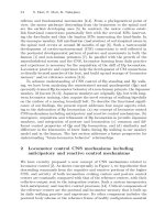
2.2 Test machine for foot roll-over shape
We built a test machine (Figure 2) to answer the question: ‘with what foot
radius can the largest disturbance be handled?’ The test machine weighs 3 [kg]
and is, with a leg length of 38 [cm], approximately half the size of MIKE. It
has no knees, the only joint is at the hip. The test machine was placed on a
shallow slope with a disturbance half-way. The disturbance was realized by
lowering the second half of the walkway. The stability was quantified as the
largest amount of lowering that the test machine could still recover from and
continue walking to the end of the slope.
0
2
4
6
8
100 200 300 400
foot radius [mm]
*
*
*
*
max disturbance [mm]
Fig. 2. Stability results of the
test machine (left) tested with
four different foot radii: 50,
100, 190 and 380 [mm] with a
foot length limited to approx.
8 [cm]. Apparently a larger
foot radius is always better
We built four different sets of feet with radii from 50 [mm] to 380 [mm],
but limited the foot length to about 8 [cm]. The results are plotted in Figure 2.
Apparently, the larger the foot radius the better, as coincides with intuition.
Of course, when the foot length is limited, there is no gain in increasing the
foot radius above a certain value; the walker would just spend more time on
the heel and toe.
2.3 Construction
Theoretically, MIKE needs feet with a radius as large as possible. In practice
however, there is a limitation to the length of the foot due to the required
foot clearance. If the foot is long, bending the knee will not result in enough
clearance for the swing leg, but rather in the opposite. Based on the empiri-
cally determined prosthetic foot shape and some experimenting with MIKE,
146 Martijn Wisse, Jan van Frankenhuyzen
eventually we decided on a foot radius of 25 [cm] and a length of 13 [cm].
This is pretty close to McGeer’s recommended 1/3 of the leg length.
Another practical consideration is the place of attachment of the foot to
the shank. McGeer shifted the feet somewhat forward from the center, so that
the passive reaction torques would keep the knees locked during the stance
phase. We don’t need this, for we have muscles to actively extend the knees.
However, empirical study showed that the best stability results were obtained
indeed with the feet shifted forward about 6 [cm], see Figure 3.
Fig. 3. In practice, we obtained the best results
withafootradiusof25[cm],afootlengthof13[cm],
and a forward displacement of 6 [cm]. The foot
switch allows the controller to adapt to the actual
step time by registering the exact instant of heel
strike
3 McKibben muscles as adjustable springs
3.1 Background and requirements
For autonomous systems, it is crucial to apply lightweight actuators. For a
passive dynamic walker, another requirement is that the actuators should
not interfere with the passive swinging motions of the legs. McGeer says the
following about this matter: “The geared motors or fluidic actuators used
on most mechanical bipeds do not satisfy this requirement; lift one of their
legs, and it will hang catatonically or, at best, grind slowly to a halt at
the bottom of its swing.” We chose to use pneumatic McKibben muscles as
actuators that fulfill these requirements. In comparison to other alternatives,
such as commercially available pneumatic cylinders, McGeer’s LITHE [7],
Direct Drive torque motors, or MIT Leglab’s Series Elastic Actuators [9],
the McKibben muscles are very lightweight and simple in construction and
application.
Under constant pressure the McKibben muscles behave like a spring with
low hysteresis. Because the muscles can only provide tension force, we use
them in a pair of antagonists, counteracting on the same passive joint (see
Figure 4). Increasing the internal pressure results in a higher spring stiffness,
which in turn increases the natural frequency of the limb.
3.2 Operating principle, technical realization and results
A McKibben muscle consists of flexible rubber tube, covered by a weave of
flexible yet non-extensible threads, see Figure 5. The operating principle is
Design and Construction of MIKE 147
Fig. 4. Overview of the McKibben muscles on MIKE. Each
muscle drawn represents two muscles performing the same
function in the machine
best explained when starting with a non-attached, pressurized muscle. If from
that state the muscle is extended, the non-extensible threads are forced into
an orientation with a smaller inter-thread angle, thus decreasing the diam-
eter of the muscle. The cumulative effect of muscle extension and diameter
0.45 MPa
0.4 MPa
0.3 MPa
0.2 MPa
40
30
20
10
0
5
10 15 20
Travel (mm)
Force
(N)
50
P
P
F
F
Fig. 5. McKibben muscles; (left top) operating principle, (left bottom) photo-
graph of the Shadow muscle, (right) force-length diagram
reduction is a decrease of muscle volume. Against an assumed constant mus-
cle pressure, reducing the muscle volume costs work. This work can only be
supplied by a tension force in the muscle attachments. In other words; mus-
cle extension causes a counteracting force, which makes the muscles act like
tension springs. A more detailed study of the McKibben muscle used as an
adjustable spring can be found in [11], where the relation between muscle
extension and tension force is presented as:
F =
b
2
P
2πn
2
L
0
∆L (1)
with F = muscle force, b = length of weave threads, P
= relative muscle
pressure, n = number of turns of a thread, L
0
= muscle rest length, and
∆L = relative muscle extension. This relation reveals the most important
characteristics of a McKibben muscle:
148 Martijn Wisse, Jan van Frankenhuyzen
• The muscles behave like linear springs,
• The spring constant is proportional to the muscle pressure.
McKibben muscles are based on a simple concept and are generally easy
to construct. However, it is our experience that the choice of materials and
connectors is important for the muscle lifetime. Therefore, we use commer-
cially available muscles (Figure 5) made by the Shadow Group [3], which
they sell at £6 each. The muscles weigh less than 10 grams and can produce
a force of 40 [N] at 0.40 [MPa].
Figure 5 shows the mechanical behavior of one type of Shadow muscle (6
mm diameter, 150 mm length) at different pressure levels. Note that indeed
the muscles behave like linear springs (in this range). Also, note that there
is a small but noticeable hysteresis-loop, representing losses mainly due to
friction between the scissoring threads and the rubber tube.
4 Pneumatic system
4.1 Background and presumptions
Because a McKibben muscle needs pressurized gas for functioning, our au-
tonomous biped MIKE needs to be provided with an efficient, lightweight
and properly working pneumatic system. First of all, we have to carry along
our own reservoir of pressurized gas. The gas should be stored at saturation
pressure in order to keep the necessary container volume as small as possible.
Secondly, the high pressure from this container has to be reduced to various
operation pressure levels between 0.1 [MPa] and 0.4 [MPa].
Minimizing gas consumption helps to increase the autonomous operation
time. Van der Linde [11] developed the so called ‘Actively Variable Passive
Stiffness’-system. This system includes a solenoid 3/2 valve that switches the
internal muscle pressure between two preset pressure levels. In this way, only
a small volume of gas is needed every time the muscle is activated, because
the muscle pressure is never completely vented to ambient pressure.
4.2 Requirements
To have time for proper experiments, we need a few minutes of autonomous
operation time on one gas container. Measurements on the amount of exhaust
gas, during a pressure decrease from 0.35 to 0.15 [MPa] in one muscle, tell
us that we need 44 milligrams CO
2
per actuation. During each step 4 muscle
activations take place, so that we need 176 milligrams of gas each step. The
step time is 0.6 seconds. By choosing an ISI CO
2
-bulb [5] with 86 grams of
gas, we have an acceptable 5 minutes of continuous experimental time.
Because our goal is to build a transportable and easy to handle biped, we
(intuitively) put the maximum total weight on 7 kg. Regarding the amount
Design and Construction of MIKE 149
(and weight) of the electrical and mechanical sub-systems, a total weight of
the pneumatic system of 1 kg seems to be acceptable.
Since the muscle pressure is directly related to the stiffness, it is important
to be able to control the pressure levels with high accuracy. A relatively short
response time is needed to make it possible to execute control actions during
a step time of 0.6 seconds.
4.3 System overview
The pneumatic system provides the actuation for our prototype MIKE. The
pneumatic system receives input from the on-board controller in the form of
valve control signals. The controller determines when each muscle is activated
or de-activated. The two respective muscle pressures are to be preset manually
when tuning the prototype. The output of the pneumatic system obviously
has the form of joint torques that influence the passive dynamic leg motions.
PRESSURE REGULATING SYSTEM (SEE FIG. 8)
McKIBBEN MUSCLE (SEE FIG. 5)
SOLENOID VALVE (SMC-
TYPE VQZ 115)
CARBONDIOXIDE-CONTAINER
Fig. 6. Overview of the pneu-
matic system on MIKE
To provide for this desired input-output behavior, the pneumatic sys-
tem consists of four components (see Figure 6): 1) gas container, 2) manu-
ally adjustable pressure reduction valves, 3) electronically controlled 3/2-way
switching valves, and 4) McKibben muscles. The pressure reduction system
is the most crucial part of the pneumatic system. We developed this system
and will present it in the next section. For the valves we use the pilot pressure
operated VQZ 115 valves from SMC [8]. Although these are about the most
efficient commercially available valves, they still consume 0.5 Watts each. We
are encouraging suppliers to develop more efficient valves. The McKibben
muscles have been discussed in the previous section.
5 Pressure control unit
5.1 Background and requirements
The pressure control unit must be able to regulate the desired muscle pres-
sures accurately and fast (well within the step time of 0.6 seconds). Second,
150 Martijn Wisse, Jan van Frankenhuyzen
application in an autonomous biped requires a compact, lightweight and gas
efficient solution.
There are two commercially available regulator principles, each of which
can only fulfill part of the above requirements. The indirectly controlled pres-
sure regulators (flapper-nozzle type) provide fast and accurate pressure con-
trol at the cost of a high internal gas consumption and relatively large physical
dimensions. Directly controlled pressure regulators (piston type) are generally
small and lightweight and need no extra gas supply for internal consumption,
but are not sensitive and accurate enough for our application. We used the
directly controlled principle, as small size and gas efficiency are the most
important requirements, and minimized the disadvantages.
5.2 Operating principle
The piston type pressure regulator is drawn in Figure 7. A valve separates
the input pressure from the output pressure. The output pressure acts on a
spring loaded piston, where the manually adjustable spring load represents
the output pressure level. If the output pressure falls below this preset value,
A
P
in
P
out
A
Exhaust
C
P
in
C
From high pressure
supply
From muscle
(via valve)
Relief into
atmosphere
To muscle (via valve)
a)
b)
Fig. 7. Working principle of (a)pres-
sure regulator valve and (b) pressure
relief valve
the spring loaded piston opens the valve and the output pressure level is
restored. To ascertain that the pressure regulator is sensitive, it needs to be
constructed with a high ratio of A:C (see Figure 7) and with low internal
friction.
The low preset pressure level is realized by integrating a separate pressure
relief valve (see Figure 7) in the muscle outlet. The spring loaded piston in
the pressure relief valve is open as long as the muscle pressure is higher than
the preset level (drawn situation).
5.3 Technical realization and results
The principles discussed above are translated into functioning prototypes.
Experiments have convinced us that the required relatively high accuracy
cannot be met by a single-stage pressure regulator, due to pressure overshoot
and steady state offset. Therefore we have divided the pressure reduction in
two stages, see Figure 8.
Design and Construction of MIKE 151
First, one main pressure regulator directly on the gas bulb brings the pres-
sure from 5.8 [MPa] to about 1.0 [MPa]. Second, a second-stage reduction
from 1.0 [MPa] to 0.2 – 0.4 [MPa], with 4 different preset manually adjustable
pressure levels, is realized in the input pressure control block (‘IN’, Figure 8).
In these valves, the pistons are equipped with diaphragms to minimize fric-
tion effects and to provide the required sensitivity and accuracy. The output
pressure control block (‘OUT’) includes four adjustable pressure relief valves.
Basically the same piston construction as in the input pressure reduction
valves has been used. The two pressure-control blocks together weigh about
180 gram and have a volume of less than 8 x 5.5 x 1.5 cubic centimeter.
After assembling the complete pneumatic system, it is possible to evaluate
the behaviour by measuring the muscle pressure in time, during a switching-
action of the described solenoid valve. Figure 8 shows the dynamic response
of the complete system (see Figure 6) when pressurized from 0.15 [MPa]
to 0.35 [MPa] and back. We obtain an accuracy/repeatability of about 10
[kPa], and a relatively slow response as was to be expected with the choice
of pressure regulator type. However, the system is fast enough according to
the successful walking results.
IN
OUT
MAIN
TO
SOLENOID
VALVE
0.2
0.25
0.3
0.35
0
0.2 0.3 0.4 0.5 0.60.1
0.15
0.4
Relative
pressure
(MPa)
Time (seconds)
Fig. 8. (left) technical drawings of pressure reduction system, (right) dynamic
response of the complete pneumatic system
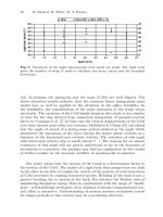
6 Walking experiments
6.1 Downhill walking
We performed walking experiments with an increasing number of active de-
grees of freedom, starting with walking down a slope with rigid knees. With
rigid knees, foot scuffing is inevitable. To eliminate this problem for our ini-
tial experiments, we constructed ’stepping stones’ at the expected footfall
152 Martijn Wisse, Jan van Frankenhuyzen
locations. Together with the slope angle this required some tuning, eventu-
ally resulting in stable walking with steps of 0.24 [m] at a slope angle of
0.06 [rad].
In this setting, we could start with experiments with rigid knees, similar
to the testing machine in Figure 2. With the Agilent HEDS-5540 incremental
optical encoder on the hip joint, the hip angle was recorded during a successful
run as shown in Figure 9. As is apparent from the figure, the gait was not
symmetrical. When the middle legs were swinging (positive hip angle), the
step was much longer in duration. Heel strike only occurred when they were
already far on their way back, noticeable by the small bump (impact shock) in
the graph. It is not clear whether this asymmetry resulted from a non-perfect
launch or from the machine’s natural dynamics. A simulation study in the
near future should reveal this. Although not symmetrical, the emergent gait
was encouraging enough to continue with experiments with bending knees.
0123456
-0.6
-0.3
0
0.3
0.6
time [s]
relative hip angle [rad]
heel
strike
heel
strike
inner
legs
swing
outer
legs
swing
manual
launch
manual
stop (catch)
01234567
-0.6
-0.3
0
0.3
0.6
time [s]
heel
strike
knee
strike
Fig. 9. Walking results (left) with stiff knees on a floor with stepping stones on
a0.06[rad]slope,(right) with active knees on a 0.06 [rad] slope. The prototype
completes 7 symmetrical steps until the end of the walking surface
By bending the knee for the appropriate time interval during the swing
phase of a leg, the prototype can gain just enough foot clearance for contin-
uous walking without stepping stones. As McGeer has shown, it is possible
to obtain the appropriate timing with pure passive dynamics by tuning the
mechanical properties. In our experience, it is then essential to keep the cen-
ter of mass of the shank very close below the knee joint. However, we want
the ability to actively interfere with the knee motion for future rough terrain
walking experiments, so MIKE was provided with knee-stretching muscles.
Having these muscles there anyway, we decided to actively control the knee
motion rather than completely rely on the passive dynamic motion.
The knee is stretched actively with a McKibben muscle counteracted by
a passive spring, see Figure 4. The default knee muscle pressure is ‘high’
(0.35 [MPa]), which is switched to ‘low’ (0.08 [MPa]) at the other leg’s heel
strike, and switched back to ’high’ after an empirically determined 400 [ms].
With this activation pattern we obtained steady walking for the entire length
Design and Construction of MIKE 153
of the slope (5 [m]) with the appearance to be able to continue to walk
indefinitely, see Figure 9. It is easy to launch the prototype by hand, so
we would call it ‘pretty stable’. We have not yet performed experiments to
determine the exact stability of the gait.
In these walking experiments MIKE has about the same specific resistance
as a walking human being, using about 10 [W] to pull its 7 [kg] along at a
speed of 0.4 [m/s]. The energy consumption consists of three components.
First, the propulsion is obtained from gravity by walking down a 0.06 [rad]
slope, which counts for 1.6 [W]. Second, the knee muscles use approximately
0.4 [MPa] CO
2
which accounts for 5.3 [W]. Actually, to keep the storage
volume small, the CO
2
is stored and supplied at the saturation pressure,
5.8 [MPa]. The inevitable loss of energy in the process of pressure reduction
from 5.8 to 0.4 [MPa] is not taken into account. Third, the prototype is
equipped with a number of sensors and a a low power (less then 1 [W]) Strong-
Arm based Linux machine (the LART [1]), which use together about 3 [W].
Obviously, the bulk of the energy consumption goes to the architecture for
improving the stability even when using low-power components. We hope to
increase the walking stability without increasing the energy consumption even
more by using the timing of the muscle activations as a control parameter [11].
6.2 Walking on level floor
Finally, we activated the hip muscles and leveled out the walking surface.
That made the robot lose its natural tendency to tilt and walk forward,
so we had to shift the center of mass forward with a few centimeters. The
hip muscles are the same as the knee muscles, but operate as antagonistic
pairs. When heel strike is detected one muscle is set to high, its antagonist
to low, so that the swing leg is pulled forward. We have not yet performed
accurate measurements on the torque that the muscles exert on the hip, but
it is estimated to be below 2.5 [Nm], approximately the same as the maximal
torque from gravity. This simple form of hip control is sufficient to obtain a
robust gait, see [12].
Mike performs a steady walk on a level floor, as demonstrated with video’s
at />. It can handle irregularities in the terrain, such as
the sidewalk in front of our building.
With the ability to walk on level ground, we finally had the opportunity
to perform an endurance test. On the 86 grams of CO
2
, MIKE can walk 3.5
minutes. After a continuous walk that long, the main pressure regulator is
deeply frozen due to gas expansion; apparently it is a little undersized for the
actual gas flow.
7 Conclusion
We started this research with the question: “How to keep the actuators and
energy storage device lightweight enough to enable autonomous operation for
154 Martijn Wisse, Jan van Frankenhuyzen
a walking biped?” Our solution is provide the biped with a pneumatic actua-
tion system. This form of actuation is successful when applying the following
two ideas: 1) use McKibben muscles as adjustable springs and 2) develop a
compact and well performing pneumatic system. With these developments
we were able to construct a fully autonomous biped. We have succeeded in
making it walk in a stable manner on a level floor, see />.
Now that we have concluded the first phase of this project, we are aiming
at the following goals: first to add an upper body while maintaining passive
dynamic properties, and finally to extend to three dimensions.
Acknowledgements
This research is funded by the Dutch national technology foundation STW.
Thanks to Richard van der Linde, Arend Schwab, Dick Plettenburg, Frans
van der Helm, Erik Mouw and Jan-Derk Bakker.
References
1. LART board. Strong-arm based low power linux machine, developed at delft
university of technology. ( />2. M. Garcia, A. Chatterjee, A. Ruina, and M. J. Coleman. The simplest walking
model: Stability, complexity, and scaling. ASME J. Biomech. Eng., 120(2):281–
288, April 1998.
3. Shadow Group. ().
4. A. H. Hansen, D. S. Childress, and E. H. Knox. Prosthetic foot roll-over shapes
with implications for alignment of trans-tibial prostheses. Prosthetics and Or-
thotics International, 24:205–215, 2000.
5. ISI. ().
6. T. McGeer. Passive dynamic walking. Intern. J. Robot. Res., 9(2):62–82, April
1990.
7. T. McGeer. Passive dynamic biped catalogue. In R. Chatila and G. Hirzinger,
editors, Proc., Experimental Robotics II: The 2nd International Symposium,
pages 465–490, Berlin, 1992. Springer–Verlag.
8. SMC pneumatics. ().
9. G. Pratt and M. Williamson. Series elastic actuators. In Proceedings of IROS
’95, Pittsburgh, PA, 1995.
10. A. L. Schwab and M. Wisse. Basin of attraction of the simplest walking model.
In Proc., International Conference on Noise and Vibration, Pennsylvania, 2001.
ASME.
11. R. Q. vd. Linde. Design, analysis and control of a low power joint for walking
robots, by phasic activation of mckibben muscles. IEEE Trans. Robotics and
Automation, 15(4):599–604, August 1999.
12. M. Wisse, A. L. Schwab, R. Q. van der Linde, and F. C. T. van der Helm. How
to keep from falling forward; elementary swing leg action for passive dynamic
walkers. Submitted to IEEE Transactions on Robotics, 2004.
Learning Energy-Efficient Walking with
Ballistic Walking
Masaki Ogino
1
, Koh Hosoda
1,2
and Minoru Asada
1,2
1
Dept. of Adaptive Machine Systems, Graduate School of Engineering,Osaka
University, 2-1 Yamadaoka, Suita, Osaka, 565-0871, Japan
2
HANDAI Frontier Research Center, Osaka University, 2-1 Yamadaoka, Suita,
Osaka, 565-0871, Japan
Abstract. This paper presents a method for energy efficient walking of a biped
robot with a layered controller. The lower layer controller has a state machine for
each leg. The state machine consists of four states: 1) constant torque is applied to
hip and knee joints of the swing leg, 2) no torque is applied so that the swing leg can
move in a ballistic manner, 3) a PD controller is used so that the certain posture
can be realized at the heel contact, which enables a biped robot to walk stably, and
4) as the support leg, hip and knee joints are servoed to go back and the torque
to support upper leg is applied. With this lower layer controller, the upper layer
controller can search parameters that enable the robot to walk as energy efficiently
as human walking without paying any attention to fall down.
1 Introduction
Comparing with human walking, bipedal walking of the current robots is
rather rigid since it does not utilize natural dynamics while human walking
does. Passive dynamic walking (PDW) is the walking mode in which a robot
can go down a shallow incline without any control nor any actuation, only
with its own mechanical dynamics [1], and it is one approach to realize natural
motion in a robot. This walking looks so similar to human walking that
many researchers have intensively studied its characteristic features and the
conditions that enable a robot to walk in a PDW manner [2][3][8][9][10][13].
Although PDW teaches us that mechanical dynamics of a robot can reduce
control efforts for walking, the structural parameters and initial conditions
to realize PDW are strictly limited, and it is not always known how we can
apply PDW properties to walking on a level floor. The properties that a
controller should have in order to realize both stable and energy efficient
walking simultaneously are not known yet.
We suppose that one of such properties is to have a control phase in which
no torque is applied to a robot, instead the gravitational and inertial force
are utilized for motion. Such kind of walking is called ”ballistic walking”.
Ballistic walking is supposed to be a human walking model suggested by
Mochon and McMahon [6]. They got the idea from the observation of human
walking data, in which the muscles of the swing leg are activated only at the
beginning and the end of the swing phase.
156 M. Ogino, K. Hosoda, M. Asada
There are a number of methods to realize ballistic walking. Taga proposed
a CPG controller that enables a human model to walk very stably with as
the same energy efficiency as human walking [14]. The torque profile of his
model shows the ballistic properties clearly. His CPG model is, however, very
complicated and it is not always necessary to use CPG to realize energy ef-
ficient walking in a robot if the same properties are realized with a simpler
controller. Actually, Linde shows that the energy efficient walking can be real-
ized by a simple controller in which muscle contraction is activated by sensor
information of foot contact [4]. Recently, Pratt demonstrated in simulation
and in a real robot that energy efficient walking is possible with a simple
state machine controller, in which the knee joint of the swing leg moves pas-
sively in the middle of the swing phase [11]. He determined the parameters
of walking by hand coding and genetic algorithm, and it is unclear to make
the energy efficient walking with learning from non-efficient walking.
In this paper, to utilize mechanical dynamics of a robot structure, we let
the hip joint free in the middle of the swing phase, and use torque control
instead of a PD controller in the beginning of the swing phase. Moreover, the
learning module is added to the state machine controller so that the minimum
energy walking can be realized.
The rest of the paper is organized as follows. First, the state machine
controller to realize ballistic walking is introduced. Next, the learning module
to optimize the parameters of the state machine controller is described. Then,
the proposed controller is applied to a biped model that has the same length
and mass to a human.
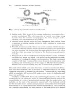
2 Ballistic walking with state machine
Here, we use a robot model consisting of 7 links: a torso, two thighs, two
shanks and two foots as shown in Fig.1. The parameters of the robot are
showninTable1.
The state machine controller at each leg consists of four states, as shown
in Fig 2: the beginning of the swing phase (swing I ), the middle of the swing
phase (swing II ), the end of the swing phase (swing III ), and the support
phase (support).
In the support phase, the hip joint is controlled with a proportional deriva-
tive (PD) manner so that the torso stands up and the support leg goes back.
To the knee joint, torque is applied so that the knee joint becomes straighten
during the support phase. Therefore, the torque applied to the hip and waist
joint are given by the following equations;
τ
1
= −K
p
(θ
1
− θ
1d
) − K
v
(
˙
θ
1
−
˙
θ
1d
) − K
wp
θ
w
− K
wv
˙
θ
w
, (1)
τ
2
= −K
p
(θ
2
− θ
2d
) − K
v
(
˙
θ
2
−
˙
θ
2d
). (2)
The reference trajectory for the above PD controllers are described with the
simple sinusoidal functions which connect the angle of the beginning of the
Learning Energy-Efficient Walking with Ballistic Walking 157
Upper Body (3.0[kg] )
Thigh (0.5[kg] )
Shank (0.5[kg] )
Foot (0.2[kg])
0.5[m]
0.3[m]
0.3[m]
0.08 [m]
w
1
2
3
Fig. 1. Robot model
support
swing I
swing II
swing III
t > Tswg1
t > Tswg1 +Tswg2
Heel Contact
(t is set to 0)
Heel Contact
of another leg
(t is set to 0)
Fig. 2. A state machine controller consisting of four states
state to the desired angle which should be realized at the end of the state,
θ
1d
(t)=
(θ
1e
−θ
1s
)
2
(1 − cos
πt
T
spt
)+θ
1s
(t<T
spt
)
θ
1e
(t ≥ T
spt
)
, (3)
˙
θ
1d
(t)=
π(θ
1e
−θ
1s
)
2T
spt
sin
πt
T
spt
(t<T
spt
)
0(t ≥ T
spt
)
, (4)
158 M. Ogino, K. Hosoda, M. Asada
θ
2d
(t)=
(θ
2e
−θ
2s
)
2
(1 − cos
πt
T
spt
)+θ
2s
(t<T
spt
)
θ
2e
(t ≥ T
spt
)
(5)
and
˙
θ
2d
(t)=
π(θ
2e
−θ
2s
)
2T
spt
sin
πt
T
spt
(t<T
spt
)
0(t ≥ T
spt
)
(6)
where θ
∗s
indicates the angle at the moment when the controller enters the
support phase (the moment of contact of the swing leg with the ground),
and θ
∗e
indicates the desired angle that should be realized at the end of the
support phase. t is the time since the controller enters to the support phase
and T
spt
is the desired time when the support phase ends. In this simulation,
the control gains are set as K
p
= 300.0 [Nm/rad], K
v
=3.0 [Nm sec/rad],
K
wp
= 300.0 [Nm/rad] and K
wv
=0.3[Nm sec/rad], and the desired angles
of the end of the support phase are set as θ
1e
=20.0 [deg] and θ
2e
=0.0
[deg].
The swing phase is separated to three states; swing I (the beginning
phase), swing II (the middle phase), and swing III (the end phase). In swing
I, the controller applies constant torque to both the hip and knee joint. After
the certain time passes, the control state changes to swing II, in which no
torque is applied to the hip and knee joints. Therefore, in swing II, the swing
leg moves in a fully passive manner. After the swing time passes T
swg2
,the
control state changes to swing III, in which the joints are servoed using PD
controllers so that the desired posture at the end of the swing phase can be
realized. By taking a certain posture at the moment of ground contact, a
certain degree of walking stability can be assured. The state of the controller
transits to the state support when the swing leg contacts with the ground.
The output torque can be summarized as the following equations,
τ
1
=
⎧
⎨
⎩
A (t<T
swg1
)
0(T
swg1
≤ t<T
swg1
+ T
swg2
)
−K
p
(θ
1
− θ
1d
) − K
v
(
˙
θ
1
−
˙
θ
1d
)(T
swg1
+ T
swg2
≤ t)
(7)
and
τ
2
=
⎧
⎨
⎩
−B (t<T
swg1
)
0(T
swg1
≤ t<T
swg1
+ T
swg2
)
−K
p
(θ
2
− θ
2d
) − K
v
(
˙
θ
2
−
˙
θ
2d
)(T
swg1
+ T
swg2
≤ t)
, (8)
where the reference trajectory in swing III is given in the same manner as
the support phase, eqs.(4)-(7). In our study, the desired angles of the hip
and knee joints at the end of the swing phase are set as θ
1e
= −20 [deg] and
θ
2e
= 0 [deg], respectively. T
swg1
and T
swg2
are set to 0.2 [sec], and 0.05 [sec].
Throughout walking, a PD controller with the weak gains (K
p
=3.0
[Nm/rad] and K
v
=0.3 [Nm sec/rad]) is used to the ankle joints,
τ
3
= −K
p
(θ
3
− θ
3d
) − K
v
(
˙
θ
3
−
˙
θ
3d
)(9)