Biomimetics - Biologically Inspired Technologies - Yoseph Bar Cohen Episode 2 Part 6 ppsx
Bạn đang xem bản rút gọn của tài liệu. Xem và tải ngay bản đầy đủ của tài liệu tại đây (658.95 KB, 30 trang )
interface between the electronics and neurons, and the matrix to enable survival of the cellular
components while being housed in microelectronics.
17.2.1 Simulations of Prosthetic Vision
One of the major arguments supporting the concept of a retinal prosthesis is the fact that cochlear
implant patients can understand speech with only six input channels. Simulations of cochlear implant
audition have shown that speech reduced to as few as four frequencies provides enough information
for the human brain to understand language. Similarly, it is hoped that visual prostheses will be able
to transmit useful information without replacing the input from all 100 million photoreceptors.
Several experiments were done to define the minimum acceptable resolution for useful vision. Early
studies in this area focused on simulating prosthetic vision from a cortical implant. The points of
stimulation (pixels) required for specific activities varied from 80 to more than 600, depending on
the activity being performed (Brindley, 1965). Most recent studies show that 625 pixels is a better
estimate for certain tasks. It was concluded that 625 electrodes implanted in a 1 cm
2
area near the
foveal representative of the visual cortex could produce a phosphene image with a visual acuity of
approximately 20/30. Such acuity could provide useful restoration of functional vision for the
profoundly blind (Cha et al., 1992a–c).
Although these studies began to delineate the number of electrodes needed, the fact that all the
pixels were projected on a very small area of the retina, made it impractical to translate to the design
of a retinal prosthesis, in which the electrodes would be spread over the entire macular region. Thus,
a low vision enhancement system (LVES) has been modified to filter images on a head mounted
display in order to simulate pixelized prosthetic vision and to produce an array of dots. The results
suggested that a fair level of visual function can be achieved for facial recognition and reading large
print text using pixelized vision parameters such as a 25 Â 25 grid in a 108 field, with high contrast
imaging and four or more gray levels.
17.3 MECHANICAL EFFECTS OF IMPLANTATION OF RETINAL PROSTHESIS
Retinal tissue is delicate and can easily tear or detach from the back of the eye. The delicate nature
of the retinal tissue can also predispose it to pressure necrosis by a chronic implant being placed on
it. Increased intraocular pressure, typical in glaucoma, can lead to damage to retinal ganglion cells
and significant visual loss. Also, there is an abundant blood supply within and underneath the retina.
Disruption of this vasculature can lead to chronic inflammation or new blood vessel formation, both
of which can lead to retinal damage. Studies have shown that an epiretinal array can be secured to
the inner retinal surface in a safe and secure manner, is mechanically stable, and biologically
tolerated over a 6-month period (Majji et al., 1999).
Any intraocular implantable device has to be tested for biocompatibility. Since these devices are
to remain within the intraocular environment for many years, they have to continue to be electric-
ally effective, and also not cause mechanical damage over time. Moreover, the device should also
not undergo long term degradation, like corrosion, in the ocular environment.
17.3.1 Infection and Inflammation
The eye, as is the central nervous system, has been described as immunological or partially
immunological privileged (Rocha et al., 1992). Despite this fact, the inflammatory course is
identical to that occurring elsewhere in the body once an incitement for inflammation has occurred
(Oehmichen, 1983). Mere surgical manipulation, any infection, biodegradation or any release of
toxic substances from a foreign body can provoke a severe inflammatory response. Bacterial
infections are often delayed and appear to be due in part to the host’s inability to respond properly
Bar-Cohen : Biomimetics: Biologically Inspired Technologies DK3163_c017 Final Proof page 432 21.9.2005 11:47pm
432 Biomimetics: Biologically Inspired Technologies
to infections. Their origins are frequently distant infected sites in the body or skin flora (Dougherty
and Simmons, 1982).
17.3.2 Ocular Side-Effects of Long Term Implantation
Since the field of retinal implants is relatively new, there are few reports available on the long-term
side-effects or complications related to implantation of a device. Sham surgeries have been done,
with no electrical stimulation, to simulate prosthetic implantation, to study the mechanical damage
to the eye. In one such study, performed in four dogs, mild retinal folds were noticed at one edge of
the array, which did not progress over time; there was no retinal detachment (RD) seen in any of the
dogs. Retinal pigment epithelium (RPE) changes were noted near the retinal tacks which are used to
fix the epiretinal implant (Majji et al., 1999). In another study (Walter et al., 1999), nine out of ten
rabbits were implanted without serious complications. The implant was found to be stable at the
original fixation site and there was no change noted in retinal architecture underneath the implant
by light microscopy. In three cases, mild cataract formation was observed, while in one case, a total
RD was found after a 6-month follow-up. In another study, three rabbits were implanted with an
electrode array in the subretinal space. No side-effects were reported (Chow and Chow, 1997).
The anatomy and physiology of the retina evaluated after implantation of a retinal implant.
Vascular integrity was evaluated by injection of fluorescent dye into the blood stream and
subsequent imaging of the dye’s presence in the ocular blood flow (a technique called fluorescein
angiography). Good vascular perfusion was noted during the entire follow-up period of more than 6
months (Majji et al., 1999). Also, in the same study, electroretinogram (ERG) findings were found
to be within reasonable limits after the surgery. There is histopathological confirmation that the
retina underneath an epiretinal array does not undergo any damage over 6 months of follow-up.
Light microscopy and electron microscopy have proved that the retinal microstructure does not
show any signs of degradation over this time, though the area around the tack showed localized loss
of retinal and RPE layers.
A single volunteer with end-stage RP has been chronically implanted with an optic nerve cuff
electrode connected to an implanted neurostimulator and antenna in February 1998. Chronic
follow-up of this patient has not shown any side-effects to the surgery or the presence of electrodes
around the optic nerve.
17.3.3 Attachment of the Implant to the Retina
Any implanted device will be exposed to the ocular movements, especially in cases where vitreous
surgery replaces the vitreous gel with fluid-filled cavity, where counter-currents from the fluid can
generate forces on the epiretinal implant; hence, it requires a stable fixation to its intended anatomic
location. Ocular rotational movements have been recorded to reach 7008 visual angle/sec. These
extreme movements can certainly dislodge the epiretinal device and move it away from the required
location. The subretinal implant will not face the same counter-current movements as an epiretinal
implant would, since it is expected to stay within the confines of the subretinal space taking the
advantage of the adherence forces between the sensory retina and the retinal pigment epithelium.
Even though the likelihood of displacement of such devices is low, they have been known to be
displaced after implantation (Peyman et al., 1998). Surgical implantation of such a device can be
either through the sclera (ab externo) or intraocularly through a retinotomy site after a vitrectomy
procedure.
There have been various approaches to the attachment of the epiretinal implant or device to the
retina. Bioadhesives, retinal tacks, and magnets have been considered and tested as some of the
methods for the array attachment. Retinal tacks and the electrode array have been shown to be
firmly attached to the retina for up to 1 year of follow-up with no significant clinical or histological
side-effects (Majji et al., 1999). Similar results were seen in rabbits (Walter et al., 1999).
Bar-Cohen : Biomimetics: Biologically Inspired Technologies DK3163_c017 Final Proof page 433 21.9.2005 11:47pm
Interfacing Microelectronics and the Human Visual System 433
There have been studies on the use of commercially available compounds for their suitability as
intraocular adhesives in rabbits. One type of adhesive (SS-PEG hydrogel, Shearwater Polymers,
Inc.) proved to be strongly adherent and nontoxic to the retina (Margalit et al., 2000). Other groups
have done similar experiments (Lowenstein et al., 1999).
The preferable fixation site for the intracortical microstimulation arrays is the cortex itself; skull
will not be a good site due to the brain’s constant movement in relation to the skull. These arrays are
currently inserted either manually in an individual fashion or in a group of 2 to 3 electrodes normal
to the cortical surface to a depth of 2 mm or by a pneumatic system that inserts 100-electrode arrays
into the cortex in about 200 msec.
17.3.4 Hermetic Sealing of the Electronics
Prostheses will be composed of electronic parts within the eye. These components will be exposed
to the chemical environment in the eye. These implanted parts will have to be sealed, such that they
are not exposed to corrosion of the ocular fluids. Also, this protective coat will have to last for some
years or decades for the continued functioning of the implant. The requirement of hermetically
sealing a circuit in the case of neural stimulating devices is complicated by the demand that
multiple conductors (feedthroughs) must penetrate the hermetic package so that the stimulation
circuit can be electrically connected to each electrode site in the array. These connections are the
most vulnerable leakage points in the system (Margalit et al., 2004).
17.4 ELECTRICAL CONSIDERATIONS IN RETINAL PROSTHETIC DEVICES
The effectiveness of an electrical stimulation for an intraocular retinal prosthesis, whether epiretinal
or subretinal, is governed by a number of parameters characteristic of the electrode array, including
shape and size of the electrodes, spacing between electrodes, electrode materials, current return
positions, and stimulating current waveform, to name a few. Optimal electrode array type and
characteristics must also take into account other factors that can influence the one or more
parameters, including thermal or electrical safety or ease of surgical implantation.
17.4.1 Stimulating Electrodes: General Considerations with Regard to Electrical
Stimulation of the Retina
The characteristics of the stimulating electrode array are often of competing nature: for example, it
might be desirable to mechanically position the electrodes as close as possible to the ganglion and
bipolar cells, but that would then result in penetrating electrodes that could harm the fragile
structure of the retina. Similarly, it may appear natural to develop small electrodes to achieve
high-resolution electrical stimulation of the retina; however, current densities needed to elicit
phosphenes may exceed safety limits and potentially cause damage to the retina. Further, it is not
completely clear, to say the least, the relation between size of the electrode and size of the visual
spot induced by that electrode.
The problem is phenomenally complex, as it simultaneously involves neural activation at the
microscopic level and control of the spread of the current in retinal tissue at the macroscopic level.
Both problems are strongly coupled and involve very different scales and methods of analysis,
which increases the complexity of solving the problem of optimal stimulation of retinal tissue and,
indirectly, the problem of optimal physical characteristics of the stimulating electrode arrays.
Besides geometrical considerations that can affect the effectiveness of the electrical stimulation
of the retinal tissue, other aspects of the system design can have a significant impact on the induced
stimulation. Among the challenges that must be considered to achieve optimal electrical stimula-
tion, in the sense of an electrical stimulation which uses as little current as possible to elicit visual
Bar-Cohen : Biomimetics: Biologically Inspired Technologies DK3163_c017 Final Proof page 434 21.9.2005 11:47pm
434 Biomimetics: Biologically Inspired Technologies
perception, there are the actual characteristics of the ‘‘contact’’ between retina and electrode, which
strongly impact the current magnitude and direction in retinal tissue. In fact, even though each layer
of the retina is characterized by a different conductivity, the vitreous humor is in general signifi-
cantly more conductive than each of the layers of the retinal tissue. The consequences of this can
easily be understood by thinking of the vitreous humor as the ‘‘preferred path’’ of the electrical
current as opposed to the retina, if the conditions are such to make this possible. Therefore, if a
stimulating electrode has its surface in contact with the vitreous humor, and not only with the retina
as it may happen for example with dome-shaped electrodes with only the tip in actual contact with
the retina, most of the current will tend to flow through the vitreous humor without passing through
the retina when the current return is located in the eyeball. This, in turn, may result in higher
currents needed to stimulate the retina and therefore elicit vision. It is therefore clear that the choice
of stimulating electrodes in terms of shape, size, and characteristics, as well as the system design in
its entirety, including the choice of the current return location for the electrodes, can have a
substantial impact on the effectiveness of the electrical stimulation of the retina. This, in turn,
has a significant impact on the feasibility of the entire system, since a more effective stimulation
will require less current, which will result in less power dissipation by the stimulating microchip,
leading to a lower temperature increase in the eye and surrounding tissue due to the operation of the
retinal prosthesis.
17.4.2 The Impedance Method for the Solution of Quasi-Static
Electromagnetic Problems
The problem of characterizing the current spread in retinal tissue, which can also lead to a better
understanding of the neural activation once coupled with models of the neural cells, can be solved
through quasi-static electromagnetic methods. A very versatile method that has a number of
benefits in the modeling of the system is the impedance method (Gandhi et al., 1984) (or admittance
method [Armitage et al., 1983]), but other methods based on the solution of the quasi-static
electromagnetic problem can be used as well (finite-element method, finite-difference method,
scalar potential finite-difference method [Dawson et al., 1996], to name a few). The impedance
method is based on the discretization of the physical model that must be modeled into computa-
tional cells. The edges of these computational cells are impedances (or admittances) which are
computed using the electrical conductivity of the material in the cell and the width, length, and
height of the computational cell. Therefore, the physical model is represented by means of an
electrical network with resistance or admittances derived from the physical properties of the
physical model itself. In its basic formulation, the impedance method uses uniform cells to
discretize the physical model; however, nonuniform cells, leading to a multiresolution impedance
method, can be used to reduce the computational time and computer memory needed to solve the
problem (Eberdt et al., 2003).
The problem of characterizing the current spread in the retina translates, therefore, into the
problem of developing an accurate model of the eye and the retina, with a geometrical resolution
sufficiently high to describe current variations on the geometrical scale of interest (DeMarco et al.,
2003). Even with the multiresolution impedance method, however, it is extremely challenging to
develop a model that reaches cellular scales in the retinal tissue and at the same time covers an
extended area such as the entire eyeball. Therefore, some compromise must be reached in terms of
resolutions vs. geometrical scales of interest for the complete characterization of the system.
A possible approach is to discretize the fine retinal structure and electrode geometries with
resolutions as low as 5 mm, for example, and subsequently use neural models with the current
levels found in the neural layers in order to model the response to electrical signals. Another
approach would be the direct coupling of the macro-scale current spread modeling with electrical
circuits to model the neural interaction. This is because in methods such as the impedance or
admittance methods, there is no restriction on the circuit element used between two nodes. In the
Bar-Cohen : Biomimetics: Biologically Inspired Technologies DK3163_c017 Final Proof page 435 21.9.2005 11:47pm
Interfacing Microelectronics and the Human Visual System 435
simplest case this is impedance related to the electrical properties of the biological tissue or
electrodes: in more complex cases it can be an arbitrarily complex circuit that can be solved with
circuit simulators such as SPICE
1
. In fact, the entire impedance or admittance network can be
solved with such circuit simulators, with subcircuits describing specific functions or particular
behaviors related to the electrical stimulation.
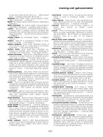
Figure 17.2 shows an example of a multiresolution computational mesh of a retinal section, with
its various layers classified and associated to a conductivity specific for each of them (Eberdt et al.,
2003). Figure 17.3 shows instead the current spread in this classified model of the retina for two
types of electrodes, coaxial electrodes and dome electrodes with side current return, respectively, as
obtained by two-dimensional multiresolution impedance method simulations. It can be qualita-
tively seen that the current magnitudes in various layers of the retina depend upon the type of
electrode. Higher resolution and coupling with neural models can also be incorporated in these
models. It should be noted, however, that there is a degree of uncertainty with respect to a number
of parameters, such as the conductivity of each layer, which is estimated based on water content and
affinity with other tissues, and actual retinal geometric features, which can be significantly distorted
in diseased retinas.
17.5 RETINAL PROSTHESIS AND RELATED THERMAL EFFECTS
An implantable device for neural stimulation should generally receive power and data wirelessly
(Rucker and Lossinsky, 1999) — through a telemetry link — process the received data, and inject
currents in the neural tissue by means of a number of stimulating electrodes that in general need to
accommodate desired waveforms, frequency of stimulation, and amplitudes of stimulating signals.
Each of these characteristics is generally responsible for power dissipation, which may result in
thermal increase in the human body in proximity of the implanted device.
A dual-unit epiretinal prosthesis (DeMarco et al., 1999; Liu et al., 2000), consisting of
an extraocular unit with an external camera for image collection, a data encoding chip, and the
primary coil for inductive power and data transfer and an intraocular unit with the secondary
coil, data processing chips, an electrode stimulator chip, and the electrode array for epiretinal
stimulation, could potentially lead to significant temperature increase in the eye and surrounding
tissues.
Figure 17.2 Example of a multiresolution computational mesh of a frog retina.
Bar-Cohen : Biomimetics: Biologically Inspired Technologies DK3163_c017 Final Proof page 436 21.9.2005 11:47pm
436 Biomimetics: Biologically Inspired Technologies
The wireless link causes electromagnetic power deposition in the head and eye tissues, which
could lead to indirect thermal rise in the tissue, known to be the dominant physiological hazard due
to power deposition in human tissues (Adair and Petersen, 2002). Moreover, the implanted
electronic IC chips will dissipate power in the form of heat, which will directly lead to the thermal
elevation in the surrounding tissues. It is therefore necessary to quantify these thermal effects in
order to determine the safe limits of operation of the prosthetic system.
The temperature rise in the head and eye tissues due to the operation of the prosthesis can be
experimentally determined with in vivo experiments or computationally evaluated by means of a
computer code for the solution of the bio-heat equation. Preliminary computational predictions
have been performed to evaluate the thermal influence of a dual-unit epiretinal prosthesis system on
the human head and eye tissues and, therefore, provide a quantitative measure of the temperature
rise in human body as a result of the operation of an implantable neurostimulator. As an example of
typical methods and results, the following paragraphs and subsections provide a brief account of the
methods and model used in such bio-engineering computations.
To quantify the thermal impact of the dual-unit epiretinal prosthesis system, the bio-heat
equation can be numerically discretized both spatially and temporally using the well-known
finite-difference time domain (FDTD) method (Sullivan, 2000; Wang and Fujiwara, 1999). In
this example, the computational prediction was performed on a very high-resolution anatomically
accurate three-dimensional human head model obtained from the National Library of Medicine
(The National Library of Medicine, The Visible Human Project, 2000). For the computational
study, the different tissues in the head model were modeled by their dielectric and thermal
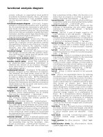
properties (DeMarco et al., 2003). Figure 17.4 shows the head model, which was utilized in the
computational domain to evaluate the natural steady state (or basal, initial) temperature distribution
in the model (due to the internal tissue metabolism with no implanted heat sources).
(a)
Figure 17.3 Qualitative image of the current spread in the frog retina due to (a) coaxial electrodes and (b) disc
electrodes. Current density values range from white (max) to black (zero).
Bar-Cohen : Biomimetics: Biologically Inspired Technologies DK3163_c017 Final Proof page 437 21.9.2005 11:48pm
Interfacing Microelectronics and the Human Visual System 437
The bio-heat equation is developed from the well-known heat equation (Necati, 1985) by con-
sidering the additional sources of thermal influence for computations involving the human body
(DeMarco et al., 2003; Bernardi et al., 2003; Gosalia et al., 2004). In the presence of implantable
devices and sources of electromagnetic power deposition, the bio-heat equation is given as:
Cr
@T
@t
¼r
.
KrTðÞþA ÀBTÀ T
B
ðÞþrSAR þ P
density
chip
|fflfflfflfflfflfflfflfflfflfflffl{zfflfflfflfflfflfflfflfflfflfflffl}
External heat sources
W
m
3
!
(17:1)
which equates the product of thermal capacitance (Cr) and temperature rise per unit time to the
different ways of accumulation of heat energy in the tissues. In Equation (17.1), the following
notations have been used:
.
r
.
KrTðÞ: thermal spatial diffusion term, which leads to heat transfer through conduction (K [J/m
.
sec
.
8C]);
.
A: tissue specific internal metabolic heat production, which will lead to an initial natural steady
state temperature distribution (J/m
3
.
sec);
.
B: tissue specific capillary blood perfusion coefficient (J/m
3
.
sec
.
8C). This has a cooling influence
proportional to the difference in tissue temperature (T) and blood temperature (T
B
);
.
rSAR and P
density
chip
: external heat sources due to electromagnetic power deposition and power
dissipated by the implanted electronics, which will lead to a thermal rise beyond the initial natural
steady state temperature distribution in the head model.
Besides the bio-heat equation, the heat exchange at the tissue interface with the external environ-
ment has to be modeled accurately. At this interface, a boundary condition to model the heat
exchange with the surrounding environment is imposed on the computations,
K
@T
@n
x; y; zðÞ¼ÀH
a
T
ðx; y; zÞ
À T
a
ÀÁ
W
m
2
!
(17:2)
Figure 17.4 Example of a three-dimensional computational head model used for numerical simulation of the
temperature increase in the tissue due to the operation of an implantable neurostimulator.
Bar-Cohen : Biomimetics: Biologically Inspired Technologies DK3163_c017 Final Proof page 438 21.9.2005 11:48pm
438 Biomimetics: Biologically Inspired Technologies
where n is perpendicular to the skin surface and the right hand expression models the heat losses
from the surface of the skin due to convection and radiation, which is proportional to the difference
between skin temperature (T
(x, y, z)
) and external environmental temperature (T
a
).
For all the computations performed in the example above, the temperature of blood was
assumed to be constant at 378C, while H
a
is the heat convection coefficient and is assumed to be
10.5 W/(m
2
.
8C). The thermal parameters for all the tissues in the head model have been directly
obtained from previous studies (DeMarco et al., 2003; Bernardi et al., 2003).
In order to validate the thermal method and model used, in vivo experiments conducted with dogs
were simulated, and experimental and computational results were compared. The experiment com-
prised of mechanically holding a heater probe (1.4 Â1.4 Â1.0 mm in size) dissipating 500 mW in the
vitreous cavity of the eye of the dog for 2 h (Gosalia et al., 2004; Piyathaisere et al., 2003). The
experimental set up included thermocouples to measure the temperature rise at different locations in
the vitreous cavity and the retina during this period. Figure 17.5 shows the comparison between the
experimentally observed and the simulated results for temperature rise at the retina and the vitreous
cavity. The uncertainty in the exact locations of the thermocouples during the actual experiment is the
likely cause of the small difference between simulated and experimental results.
17.5.1 Heat and the Telemetry System
As mentioned in the preceding paragraphs, the wireless telemetry system can be a source of thermal
rise since it causes deposition of electromagnetic (EM) power in the head and eye tissues. Using the
FDTD technique, the deposited EM power can be quantified in terms of the specific absorption rate
(SAR) and several studies have quantified the thermal effects in the human head and eye tissues
based on the evaluated SAR using the bio-heat equation (DeMarco et al., 2003; Bernardi et al.,
1998, 2000; Hirata et al., 2000). SAR is expressed as sE
*
2
= 2rðÞfor conductivity s, electric field E
*
,
0
0
10
20
30
40
50
60
70
80
90
100
10 20 30 40
Time, minutes
50 60 70 80
Temperature, ЊC
Thermal rise observed in experiments vs. simulation
Experimental : Heater
Experimental : Mid-vitreous
Simulation : Mid-vitreous
Simulation : Heater
Figure 17.5 Comparison between observed experimental results and computationally derived results for an
experiment designed to validate the computational models. (From Gosalia K, Weiland J, Humayun M, and Lazzi G.
IEEE Transactions on Biomedical Engineering, 51(8): 1469–1477, 2004. With permission.)
Bar-Cohen : Biomimetics: Biologically Inspired Technologies DK3163_c017 Final Proof page 439 21.9.2005 11:48pm
Interfacing Microelectronics and the Human Visual System 439
and mass density r at each cell (x, y, z) in the computational model. In the radiofrequency range, the
IEEE/ANSI (IEEE standard safety levels, 1999) safety limit for peak 1-g EM power deposition is
1.6 W/kg for the general population (the reader is encouraged to refer to the standard for a detailed
description of maximum permissible exposure [MPE], SAR, and effect of the frequency for EM
safety considerations). In general, if the EM power deposition remains well within this limit, the
thermal effects induced will be negligible. Therefore, it is necessary to quantify the EM power
deposition in the head tissues due to the wireless telemetry link to establish if there could be
potential hazards. As an example and to illustrate the procedure, we have used a circular coil of
approximately 37 mm diameter modeled at a distance of 20 mm from the eye and excited by a 2 A
current at the center operation frequency of 10 MHz. Computed peak 1-g SAR observed in the head
model due to such an excitation was 0.02 W/kg. At this currently estimated operating current level
for the wireless telemetry link, the SAR values do not exceed the IEEE safety limits for power
absorption (IEEE Standard exposure to RF, 1999). Thus, it can be reasonably concluded that the
contribution of SAR to the final temperature elevation would be negligible compared to the rise in
temperature due to power dissipation in the implanted chip. In these cases, the power dissipation
due to the implanted chip and coil alone can be considered as the extraneous heat source (besides
the natural metabolism of the eye).
However, it should be noted that this will not always be the case. The peak 1-g SAR value
directly depends upon the wireless link employed for supplying power and data to the implanted
device, the geometrical characteristics of the wireless devices, the frequency of operation, their
placement with respect to the human body, and their power level. In general, one must evaluate the
SAR to ensure that it is within guidelines and determine whether such SAR could result in a thermal
increase and therefore would need to be included in the bio-heat equation.
17.5.2 Power Dissipation of Implanted Electronics
In order to compute the thermal elevation due to implanted electronics, the implanted chip was
modeled in the three-dimensional head model. The chip was modeled to have a composite thermal
conductivity K ¼60 J/(m sec 8C) and encapsulated in a 0.5-mm thick layer of insulation (K ¼60
J/[m sec 8C]). These values of thermal conductivity are very high compared to the values of the
tissues in the human head (Gosalia et al., 2004).
When an actual prosthesis is implanted, there are several parametric options that can be
explored to minimize the thermal elevation in the surrounding tissues. In order to characterize
these options, several thermal simulations were performed with the chip modeled with different
sizes, placed at different locations (within the eyeball) and also dissipating different amounts of
power in order to gain an insight into the best possible configuration (from the point of view of least
thermal elevation) for an implant in the eye.
As an example of the impact of the location of the implanted microchip on the temperature
increase, we considered two locations for positioning the implanted unit within the eyeball of the
patient. In the first case, the lens can be removed and the implanted chip hinged between the ciliary
muscles of the eye (referred to as the anterior position). The other considered position is in the
middle of the vitreous cavity parallel to the axis of the eyeball (referred to as the center position).
Both these cases were characterized computationally. The implanted chip was modeled at both
these locations and thermal simulations were performed to study the variation in temperature
increase in different human head tissues as a function of the implant location.
For both the above cases, the size of the implanted chip was kept constant at 4 Â 4 Â 0.5 mm
and was allowed to dissipate 12.4 mW (anticipated worst case power dissipation from an implanted
current stimulator chip driving a 16 electrode array positioned on the retina). The power density for
each cell of the model of the chip was calculated from the total power dissipated (12.4 mW) and was
kept uniform throughout the total volume of the chip (it should be noted that uniform power
dissipation is a further simplification since such an implanted device could, in effect, exhibit
Bar-Cohen : Biomimetics: Biologically Inspired Technologies DK3163_c017 Final Proof page 440 21.9.2005 11:48pm
440 Biomimetics: Biologically Inspired Technologies
nonuniform ‘‘hot-spots’’). It was observed that within 26 min of actual stimulation time (because of
the extremely small time step in the FDTD simulations, the actual simulation time was significantly
higher), the thermal elevation profiles in the tissues reached to within 5 to 7% of their final values.
Since this provided a good indication of the approximate thermal rise, all the simulations were
performed for approximately 26 min (physical time).
The maximum temperature increase for both chip positions was observed on the surface of
the insulating layer. In both cases, the maximum thermal increase was approximately 0.828C. In the
first case where the chip was placed in the anterior position, the temperature of the ciliary muscles
rose by 0.368C as compared to 0.198C when the chip was placed in the center position. In
the vitreous cavity, temperature rise was 0.268C for the chip placed in center of the eye while the
anterior chip raised its temperature by 0.168C (Gosalia et al., 2004).
A chip placed in the anterior chamber of the eye raised the temperature of the retina by less than
half the amount that a chip placed in the center did (0.05 8C by anterior chip as compared to 0.128C
by a center chip) (Gosalia et al., 2004). In these simulations, it was observed that the vitreous cavity
was acting as a heat sink since the rise in temperature of tissues beyond the eyeball is very small.
A graphic comparison of the thermal elevation observed for the anterior and the center placed chips
is provided in Figure 17.6. The anterior position is certainly preferable for the implanted unit in
order to minimize the temperature rise in the vitreous cavity and on the retina.
A similar analysis can be performed to compute the impact of the size of the implant and
dissipated power on the temperature increase in the tissue (Gosalia et al., 2004). It is worth pointing
out, however, that power dissipation of the implanted microchip is probably the most significant
parameter among all to be considered.
Two cases were considered in this example: in the first case, the chip dissipated 12.4 mW
and in the second case, it dissipated 49.6 mW. For both of these cases, the size of the chip was
0
0.1
0.2
0.3
0.4
0.5
0.6
0.7
0.8
0.9
Temperature increase (ЊC)
Influence of POSITION of Implant on tissue heating
Insulation of the chip
Anterior position of the chip
Mild-vitreous position of the chip
4 8 12 16 20 24
Time (min)
Vitreous cavity
Retina
Figure 17.6 Thermal rise observed due to different locations of the implanted chip (anterior and center of the
eyeball). (From Gosalia K, Weiland J, Humayun M, and Lazzi G. IEEE Transactions on Biomedical Engineering,
51(8): 1469–1477, 2004. With permission.)
Bar-Cohen : Biomimetics: Biologically Inspired Technologies DK3163_c017 Final Proof page 441 21.9.2005 11:48pm
Interfacing Microelectronics and the Human Visual System 441
4 Â 4 Â 0.5 mm and it was placed in the center of the eyeball. Power density was again kept
uniform throughout the chip. The computation was performed for 26 min of simulated physical
time.
Figure 17.7 graphically compares the temperature increase observed on the insulation, in the
vitreous cavity and on the retina for both cases. From the thermal elevation results, it is observed
that increasing the power dissipation by a factor of 4 does not necessarily lead to a rise in the
temperature by the same factor. In the majority of tissues, a temperature rise by a factor of around
3.5 to 5 is observed for a four times increase in the power dissipation in the implant.
This preliminary investigation provided a qualitative and quantitative estimate of the thermal
influence of such an implanted prosthetic system in the eye. Also, in the actual system, the various
parametric variations can be optimized to yield the least harmful configuration from the point of
view of thermal damage to the tissues of the eye of head. Several efforts are currently underway to
accurately quantify the contribution of each aspect of such a prosthetic configuration to the eventual
thermal and electromagnetic influence on the human tissues.
17.6 FUTURE IMPLICATIONS
A retinal prosthesis will form several interfaces with the eye including thermal, electrical, and
mechanical. All of these interfaces must be considered simultaneously during the design of a safe
and effective retinal prosthesis. For example, it may be possible to reduce the thermal concerns by
using a larger electrode that consumes less power. However, such an electrode may stimulate a
large area of the retina and not allow fine resolution vision. Many other optimization problems are
presented by such a complex interaction. Therefore, future designs may well need to use automated
optimization algorithms to yield the most effective device.
0
0
0.25
0.75
0.50
1.00
1.25
1.75
2.00
2.25
2.50
2.75
3.00
1.50
10 20 30
Power dissipation in the chip (mW)
40 50 60
Temperature Increase (Њ C)
Influence of POWER DISSIPATION of implant on tissue heating
Retina
Vitreous cavity
Insulation of the chip
Figure 17.7 Variation of the temperature as a function of the power dissipated by the retinal implant chip.
Bar-Cohen : Biomimetics: Biologically Inspired Technologies DK3163_c017 Final Proof page 442 21.9.2005 11:48pm
442 Biomimetics: Biologically Inspired Technologies
While future implants will depend on the continued advances in technology, the success of these
implants (i.e., helping the blind see) will be jeopardized if we do not understand the neurobiology of
the electrically stimulated visual system (Weiland and Humayun, 2003). The sense of vision is
enormously complex and the nervous system has the ability to remodel in response to new stimuli.
The development of prototypes that can be permanently implanted in research animals now gives
us the ability to study these effects by applying advanced microscopy and tissue labeling methods
developed in neuroscience basic research. While these studies are absolutely necessary and will
yield valuable information, human implant studies are the only way to verify the effectiveness of
the devices. Therefore, a multifaceted effort including technology development, biological re-
search, and strict monitored, limited human tests is needed to advance the current artificial vision
devices from proof-of-principle to accepted clinical treatment for blindness.
17.7 SUMMARY
The work in visual prostheses has come a long way from the days of laboratory research and the
initial volunteer experiments. Today, we have a few patients implanted with the actual device; these
devices have shown no major side-effect or complication related to surgery. Some of these patients
have shown encouraging responses. Artificial visual stimulus is being tried at various levels, from
the retina all the way to the cortex. Each type of implant has its own advantages and problems. The
implant has to be not only biocompatible, but also be able to avoid damage from corrosion in the
biological spaces the device will be implanted in. Long term damage from electrical current is an
issue, as is the issue with the type of vision generated by the blind patients through these implants.
There are several challenges involved and issues to be considered during the design and
development of a retinal prosthetic system, which can restore a limited form of vision. The
electrical considerations of the prosthetic system (size and shape of electrodes, magnitude of
current injection, size and shape of the implanted unit and its power dissipation, frequency, and
strength of the wireless telemetry link) are closely coupled with safety considerations of the entire
system (maximum allowable current densities and thermal elevation). These issues have to be
resolved to realize a safe and effective retinal prosthesis system or any other implantable neuro-
stimulator with a large number of channels. Several electromagnetic methods and computational
techniques are being utilized to investigate the electrical performance characteristics of a prosthetic
implant. The impedance (or admittance) method coupled with the multiresolution meshing scheme
(to represent the intricate details of the retinal tissues — with a 5 mm resolution) appears very
promising for characterizing the current spread in the retinal layers for given current stimulation
and electrode array parameters. The computational implementation of the bio-heat equation
through the FDTD method has been utilized to characterize the thermal elevation in the eye and
head tissues due to the operation of the wireless telemetry link and power dissipation of the implant.
Both these numerical techniques employ a very high spatial resolution and anatomically accurate
model of the human head and eye. Tissues are represented by their dielectric and thermal properties
as required for the specific computational investigation. Using these methods, it is possible to
optimize the performance of an implantable neurostimulator such as the epiretinal prosthesis
system with respect to effectiveness of stimulation and power dissipation.
REFERENCES
Adair ER and Petersen RC. Biological effects of radiofrequency/microwave radiation. IEEE Transactions on
Microwave Theory and Techniques, 50:953–962, March 2002.
Armitage DW, LeVeen HH, and Pethig R. Radiofrequency-induced hyperthermia: computer simulation of
specific absorption rate distributions using realistic anatomical models. Physics in Medicine and
Biology, 28:31–42, 1983.
Bar-Cohen : Biomimetics: Biologically Inspired Technologies DK3163_c017 Final Proof page 443 21.9.2005 11:48pm
Interfacing Microelectronics and the Human Visual System 443
Bak M, Girvin JP, Hambrecht FT, Kufta CV, Loeb GE, and Schnidt EM. Visual sensations produced by
intracortical microstimulation of the human occipital cortex. Medical and Biological Engineering and
Computing, 28:257–259, 1990.
Bernardi P, Cavagnaro M, Pisa S, and Piuzzi E. SAR distribution and temperature increases in an anatomical
model of the human eye exposed to the field radiated by the user antenna in a wireless LAN. IEEE
Transactions on Microwave Theory and Techniques, 46:2074–2082, December 1998.
Bernardi P, Cavagnaro M, Pisa S, and Piuzzi E. Specific absorption rate and temperature increases in the head
of a cellular phone user. IEEE Transactions on Microwave Theory and Techniques, 48:1118–1126,
July 2000.
Bernardi P, Cavagnaro M, Pisa S, and Piuzzi E. Specific absorption rate and temperature elevation in a subject
exposed in the far field of radio-frequency sources operating in the 10–900 MHz range. IEEE
Transactions on Biomedical Engineering, 50:295–304, March 2003.
Berson EL, Rosner B, Sandberg MA, Hayes KC, Nicholson BW, Weigel-DiFranco C, and Willett WA.
A randomized trial of vitamin A and vitamin E supplementation for retinitis pigmentosa (see com-
ments). Archives of Ophthalmology, 111:761–772, 1993.
Brabyn JA. New developments in mobility and orientation aids for the blind. IEEE Transactions on Biomed-
ical Engineering, 29:285–289, 1982.
Button J and Putnam T. Visual responses to cortical stimulation in the blind. Journal of Iowa State Medical
Society, 52:17–21, 1962.
Brindley GS. The number of information channels needed for efficient reading. Journal of Physiology, 177:44,
1965.
Brindley GS and Lewin WS. The sensations produced by electrical stimulation of the visual cortex. Journal of
Physiology, 196:479–493, 1968.
Brindley G and Rushton D. Implanted stimulators of the visual cortex as visual prosthetic devices.
Transactions of the American Academy of Ophthalmology and Otolaryngology, 78:OP741–OP745,
1974.
Cha K, Horch KW, and Normann RA. Simulation of a phosphene-based visual field: visual acuity in a
pixelized vision system. Annals of Biomedical Engineering, 20:439–449, 1992a.
Cha K, Horch KW, and Normann RA. Mobility performance with a pixelized visual system. Vision Research,
32:1367–1372, 1992b.
Cha K, Horch KW, Normann RA, and Boman DK. Reading speed with a pixelized vision system. Journal of
Optical Society of America, 9:673–677, 1992c.
Chen SJ, Humayun MS, and Weiland JD. Electrical stimulation of the mouse retina: a study of electrically
elicited visual cortical responses. The Association of Research in Vision and Ophthalmology Annual
Meeting, 1999; Fort Lauderdale. Abstract 3886 S736.
Chiang YP, Bassi JL, and Javitt JC. Federal budgetary costs of blindness. Milbank Q, 70:319–340, 1992.
Chow AY and Chow VY. Subretinal electrical stimulation of the rabbit retina. Neuroscience Letters,
225:13–16, 1997.
Chow AY and Peachey NS. The subretinal microphotodiode array retinal prosthesis (letter; comment).
Ophthalmic Research, 30:195–198, 1998.
Crapper DR and Noell WK. Retinal excitation and inhibition from direct electrical stimulation. Journal of
Neurophysiology, 6:924–947, 1963.
Curcio CA, Medeiros NE, and Millican CL. Photoreceptor loss in age-related macular degenration. Investi-
gative Ophthalmology Visual Science, 37:1236–1249, 1996.
Dawson TW, De Moerloose J, and Stuchly MA. Comparison of magnetically induced ELF fields in humans
computed by FDTD and scalar potential FD codes. Applied Computational Electromagnetics Society,
11:63–71, 1996.
DeMarco SC, Clements M, Vichienchom K, Liu W, Humayun M, de Juan EJ, Weiland J, and Greenberg
RJ. An epi-retinal visual prosthesis implementation. Annual Conference BMES, vol. 1, p. 475, 1999.
DeMarco SC, Lazzi G, Liu W, Weiland JD, and Humayun MS. Computed SAR and thermal elevation in a 0.25
mm 2-D model of the humal eye and head in response to an implanted retinal stimulator: parts 1 and 2.
IEEE Transactions on Antennas and Propagation, 51(9):2274–2286, 2003.
Dobelle WH and Mladejovsky MG. Phosphenes produced by electrical stimulation of human occipital cortex,
and their application to development of a prosthesis for the blind. Journal of Physiology, 243:553–576,
1974.
Bar-Cohen : Biomimetics: Biologically Inspired Technologies DK3163_c017 Final Proof page 444 21.9.2005 11:48pm
444 Biomimetics: Biologically Inspired Technologies
Dobelle WH, Mladejovsky MG, Evans JR, Roberts TS, and Girvin JP. ‘‘Braille’’ reading by a blind volunteer
by visual cortex stimulation. Nature, 259:111–112, 1976.
Dougherty SH and Simmons RL. Infections in bionic man: the pathobiology of infections in prosthetic devices
— part II. Current Problems in Surgery, 19:265–319, 1982.
Eberdt M., Brown PK, and Lazzi G. Two-dimensional SPICE-linked multiresolution impedance method for
low-frequency electromagnetic interactions. IEEE Transactions on Biomedical Engineering, 50, 881–
889, July 2003.
Eckmiller R. Learning retina implants with epiretinal contacts. Ophthalmic Research, 29:281–289, 1997.
Foerster O. Beitrage zur pathophysiologie der sehban und der spehsphare. Journal of Psychology and
Neurology (Lpz), 39:435–463, 1929.
Gandhi OP, DeFord JF, and Kanai H. Impedance method for calculation of power deposition patterns in
magnetically induced hyperthermia. IEEE Transactions on Biomedical Engineering, 31:644–651,
1984.
Gosalia K, Weiland J, Humayun M, and Lazzi G. Thermal elevation in the human eye and head due to the
operation of a retinal prosthesis. IEEE Transactions on Biomedical Engineering, 51(8):1469–1477,
2004.
Greenberg RJ, Velte TJ, Humayun MS, Scarlatis GN, and de Juan E Jr. A computational model of electrical
stimulation of the retinal ganglion cell. IEEE Transactions on Biomedical Engineering, 46:505–514,
1999.
Guenther E, Troger B, Schlosshauer B, and Zrenner E. Long term survival of retinal cell cultures on retinal
implant materials. Vision Research, 39:3988–3994, 1999.
Hirata A, Matsuyama SI, and Shiozawa T. Temperature rises in the human eye exposed to EM waves in the
frequency range 0.6–6 GHz. IEEE Transactions on Electromagnetic Compatibility, 42:386–393,
2000.
Humayun MS, de Juan E Jr, Dagnelie G, Greenberg RJ, Propst RH, and Phillips DH. Visual perception elicited
by electrical stimulation of retina in blind humans. Archives of Ophthalmology, 114:40–46, 1996.
Humayun MS, Prince M, de Juan EJ, Barron Y, Moskowitz M, Klock IB, and Milam AH. Morphometric
analysis of the extramacular retina from postmortem eyes with retinitis pigmentosa. Investigative
Ophthalmology and Visual Science, 40:143–148, 1999a.
Humayun MS, de Juan EJ, Weiland JD, Dagnelie G, Katona S, Greenberg RJ, and Suzuki S. Pattern electrical
stimulation of the human retina. Vision Research, 39:2569–2576, 1999b.
IEEE Standard for Safety Levels With Respect to Human Exposure to Radio Frequency Electromagnetic
Fields. 3 kHz to 300 GHz. IEEE Standard C95.1, 1999.
Jones KE and Normann RA. An advanced demultiplexing system for physiological stimulation. IEEE
Transactions on Biomedical Engineering, 44:1210–1220, 1997.
Kanda H, Morimoto T, Fujikado T, Tano Y, Fukuda Y, and Sawail H. Electrophysiological studies of the
feasibility of suprachoroidal–transretinal stimulation for artificial vision in normal and RCS rats.
Investigative Ophthalmology and Visual Science, 45:560–566, 2004.
Karny H. Clinical and physiological aspects of the cortical visual prosthesis. Surveys of Ophthalmology,
20:47–58, 1975.
Kim A, Sadda S, Pearlman J, Humayun M, de Juan EJ, Melia M, and Green WR. Morphometric analysis of the
macula in eyes with disciform age-related macular degeneration. Retina, 22: 471–477, 2002.
Lederman RJ, Noell WK. Optic nerve population responses to transretinal electrical stimulation. Vision Re-
search, 9:1041–1052, 1969.
Liu W, Vichienchom K, Clements M, DeMarco SC, Hughes C, McGucken E, Humayun MS, de Juan EJ,
Weiland JD, and Greenberg RJ. A neurostimulus chip with telemetry unit for retinal prosthetic device,
IEEE Journal of Solid-State Circuits, 35:1487–1497, October 2000.
Lowenstein J, Rizzo JF, Shahin M, Coury A. Novel retinal adhesive used to attach electrode array to retina.
The Association for Research in Vision and Ophthalmology Annual Meeting, 1999; Fort Lauderdale.
Abstract 3874.
Majji AB, Humayun MS, Weiland JD, Suzuki S, D’Anna SA, and de Juan E Jr. Long term histological and
electrophysiological results of an inactive epiretinal electrode array implantation in dogs. Investigative
Ophthalmology and Visual Science, 40:2073–2081, 1999.
Margalit E, Fujii G, Lai J, Gupta P, Chen S, Shyu J, Piyathaisere DV, Weiland JD, de Juan E Jr., and Humayun
MS. Bioadhesives for intraocular use. Retina, 20:469–477, 2000.
Bar-Cohen : Biomimetics: Biologically Inspired Technologies DK3163_c017 Final Proof page 445 21.9.2005 11:48pm
Interfacing Microelectronics and the Human Visual System 445
Margalit E, Dagnelie G, Weiland JD, de Juan E, and Humayun MS. Can vision be restored by electrical
stimulation? In: Horch KW and Dhillon GS (eds) (Chapter 7.5) Nueroprostheses: Theory and Practice.
Singapore: World Scientific, 1067–1102, 2004.
Maynard EM, Nordhausen CT, and Normann RA. The Utah intracortical electrode array: a recording structure
for potential brain–computer interfaces. Electroencephalography and Clinical Neurophysiology,
102:228–239, 1997.
Maynard EM. Visual prostheses. Annual Review of Biomedical Engineering, 3:145–168, 2001.
Nordhausen CT, Maynard EM, and Normann RA. Single unit recording capabilities of a 100 microelectrode
array. Brain Research, 726:129–140, 1996.
Necati O. Heat Transfer: A Basic Approach. New York: McGraw Hill, 1985.
Normann RA, Maynard EM, Rousche PJ, and Warren DJ. A neural interface for a cortical vision prosthesis.
Vision Research, 39:2577–2587, 1999.
Oehmichen M. Inflammatory cells in the central nervous system: an integrating concept based on recent
research in pathology, immunology and forensic medicine. Progress in Neuropathology, 5:277–335,
1983.
Peterman MC, Mehenti NZ, Bilbao KV, Lee CJ, Leng T, Noolandi J, Bent SF, Blumenkranz MS, and Fishman
HA. The artificial synapse chip: a flexible retinal interface based on directed retinal cell growth and
neurotransmitter stimulation. Artificial Organs, 27(11):975–985, 2003.
Peyman G, Chow AY, Liang C, Chow VY, Perlman JI, and Peachey NS. Subretinal semiconductor micro-
photodiode array. Ophthalmic Surgical Lasers, 29:234–241, 1998.
Piyathaisere DV, Margalit E, Chen SJ, Shyu JS, D’Anna SA, Weiland JD, Grebe RR, Grebe L, Fujii G, Kim
SY, Greenberg RJ, de Juan EJ, and Humayun MS. Heat effects on the retina. Ophthalmology Surgery
and Lasers Imaging, 34(2):114–120, 2003.
Pollen DA. Responses of single neurons to electrical stimulation of the surface of the visual cortex. Brain,
Behavior and Evolution, 14:67–86, 1977.
Potts AM and Inoue J. The electrically evoked response (EER) of the visual system II. Effect of adaptation and
retinitis pigmentosa. Investigative Ophthalmology, 8:605–612, 1969.
Potts AM and Inoue J. The electrically evoked response of the visual system (EER) III. Further consideration to
the origin of the EER. Investigative Ophthalmology, 9:814–819, 1970.
Potts AM, Inoue J, and Buffum D. The electrically evoked response of the visual system (EER). Investigative
Ophthalmology, 7:269–278, 1968.
Ranck JB Jr. Which elements are excited in electrical stimulation of mammalian central nervous system:
a review. Brain Research, 98:417–440, 1975.
Rita P, Kaczmarek ME, Tyler ME, and Garcia-Lara J. Form perception with a 49-point electrotactile stimulus
array on the tongue: a technical note. Journal of Rehabilitation Research and Development, 35:427–
430, 1998.
Rizzo J. and Wyatt J. Prospects for a visual prosthesis. Neuroscientist, 3:251–262, 1997.
Rizzo J, Wyatt J, Loewenstein J, and Kelly S. Acute intraocular retinal stimulation in normal and blind
humans. The Association of Research in Vision and Ophthalmology Annual Meeting, 2000; Fort
Lauderdale. Abstract 532 S102.
Rocha G, Baines MG, and Deschenes J. The immunology of the eye and its systemic interactions. Critical
Reviews of Immunology, 12:81–100, 1992.
Rucker L and Lossinsky A. Percutaneous Connectors. 30th Neural Prosthesis Workshop, NINDS, NINCD,
NIH, October 1999.
Santos A, Humayun MS, de Juan EJ, Greenberg RJ, Marsh MJ, Klock IB, and Milam AH. Preservation of the
inner retina in retinitis pigmentosa. A morphometric analysis. Archives of Ophthalmology, 115:511–
515, 1997.
Schmidt EM, Bak MJ, Hambrecht FT, Kufta CV, O’’Rourke DK, and Vallabhanath P. Feasibility of a visual
prosthesis for the blind on intracortical microstimulation of the visual cortex. Brain, 119(Pt 2):507–
522, 1996.
Shimazu K, Miyake Y, and Watanabe S. Retinal ganglion cell response properties in the transcorneal
electrically evoked response of the visual system. Vision Research, 39:2251–2260, 1999.
Stone JL, Barlow WE, Humayun MS, de Juan EJ, and Milam AH. Morphometirc analysis of macular
photoreceptors and ganglion cells in retinas with retinitis pigmentosa. Archives of Ophthalmology,
110:1634–1639, 1992.
Bar-Cohen : Biomimetics: Biologically Inspired Technologies DK3163_c017 Final Proof page 446 21.9.2005 11:48pm
446 Biomimetics: Biologically Inspired Technologies
Sullivan D. Electromagnetic Simulation Using the FDTD Method. New York: IEEE Press, 2000.
Suzuki S, Humayun MS, de Juan E Jr, Weiland JD, and Barron YA. A comparison of electrical stimulation
threshold in normal mouse retina vs. different aged retinal degenerate (rd) mouse retina. The Associ-
ation of Research in Vision and Ophthalmology Annual Meeting, 1999; Fort Lauderdale. Abstract
3886 S735.
Tassicker. (US 2760483). 1956. Ref Type: Patent.
The National Library of Medicine. The Visible Human Project. (Online). Available: />research/visible/visible_human.html, 2000.
Uematsu S, Chapanis N, Gucer G, Konigsmark B, and Walker AE. Electrical stimulation of the celebral visual
system in man. Confinia Neurologica, 36:113–124, 1974.
Veraart C, Wanet-Defalque MC, Gerard B, Vanlierde A, and Delbeke J. Pattern recognition with the optic
nerve visual prosthesis. Artificial Organs, 27(11):996–1004, 2003.
Walter P, Szurman P, Vobig M, Berk H, Ludtke-Handjery HC, Richter H, Mittermayer C, Heimann K, and
Sellhaus B. Successful long term implantation of electrically inactive epiretinal microelectrode arrays
in rabbits. Retina, 19:546–552, 1999.
Wang J and Fujiwara O. FDTD computation of temperature rise in the human head for portable telephones.
IEEE Transactions on Microwave Theory and Techniques, 47:1528–1534, August 1999.
Weiland JD, Humayun MS. Suzuki S, D’Anna SA, and de Juan E Jr. Electrically evoked response (EER) from
the visual cortex in normal and retinal degenerate dog. The Association of Research in Vision and
Ophthalmology Annual Meeting, 1999; Fort Lauderdale. Abstract 4125 S783.
Weiland JD and Humayun MS. Past, present and future of artificial vision. Artificial Organs, 27(11):961–962,
2003.
Yagi T and Watanabe M. A computional study on an electrode array in a hybrid retinal implant. Proceedings of
1998 IEEE International Joint Conference on Neural Networks, 780–783, 1998.
Zrenner E, Miliczek KD, Gabel VP, Graf HG, Guenther E, Haemmerle H, Hoefflinger B, Kohler K, Nisch W,
Schubert M, Stett A, and Weiss S. The development of subretinal microphotodiodes for replacement of
degenerated photoreceptors. Ophthalmic Research, 29(5): 269–280, 1997.
Zrenner E, Stett A, Weiss S, Aramant RB, Guenther E, Kohler S, Miliczek KD, Seiler MJ, and Hammerle H.
Can subretinal microphotodiodes successfully replace degenerated photoreceptors? Vision Research,
39:2555–2567, 1999.
Zrenner E. Will retinal implants restore vision? Science, 295:1022–1025, 2002.
Bar-Cohen : Biomimetics: Biologically Inspired Technologies DK3163_c017 Final Proof page 447 21.9.2005 11:48pm
Interfacing Microelectronics and the Human Visual System 447
Bar-Cohen : Biomimetics: Biologically Inspired Technologies DK3163_c017 Final Proof page 448 21.9.2005 11:48pm
18
Artificial Support and Replacement
of Human Organs
Pramod Bonde
CONTENTS
18.1 Introduction 450
18.2 Historical Perspective 450
18.3 Artificial Kidney 451
18.4 Artificial Liver 452
18.5 Heart and Lung Machine 453
18.6 Artificial Lung 454
18.7 Ventricular Assist Devices 454
18.7.1 Centrifugal Pumps 456
18.7.2 Paracorporeal Devices 456
18.7.3 Intracorporeal Devices 456
18.7.4 Newer Rotary Axial Pumps 457
18.8 Total Artificial Heart 459
18.8.1 AbioCor Total Artificial Heart (ABIOMED, Inc, Denver, CO) 460
18.8.2 CardioWest TAH (SynCardia Systems, Inc., Tucson, AZ) 460
18.8.3 Penn State TAH (ABIOMED, Inc., Denver, CO) 460
18.9 Total Joint Replacements 461
18.10 Bio-Artificial Pancreas 462
18.11 Visual Prosthesis (Artificial Eye) 462
18.12 Artificial Skin Substitutes 463
18.13 Artificial Blood 463
18.14 Other Substitutes 464
18.15 Limitations of the Current Organ Replacement Systems 464
18.15.1 Impact of Other Technologies 464
18.15.1.1 Tissue Engineering 464
18.15.1.2 Stem Cell Technology 465
18.15.1.3 Impact of Understanding the Human Genome 465
18.15.1.4 Microelectromechanical Systems 465
18.15.2 Nanotechnology and Biomimetics 466
18.16 Summary 466
References 467
Bar-Cohen : Biomimetics: Biologically Inspired Technologies DK3163_c018 Final Proof page 449 21.9.2005 3:40am
449
18.1 INTRODUCTION
Heart disease is a leading cause of death and contributes to 29% of total deaths in USA (Anderson
and Smith, 2003). About five million people suffer from heart failure each year with additional
500,000 being diagnosed new every year (AHA, 2003). Approximately 1,000,000 will die within
2 years of their diagnosis. Heart transplant is the only definitive therapy for these patients
(Baumgartner et al., 2002). Respiratory failure accounts for the fourth leading cause of death
followed by kidney and liver failure (Anderson and Smith, 2003). The current gold standard for
treating organ failure is transplantation (UNOS, 2003). There are strict criteria for patients to be
accepted as suitable candidates for transplantation and in 2002, there were close to 80,000 patients
in the USA on the waiting list to receive organ transplantation (UNOS, 2003). During the same year
24,000 received a transplant, with a majority (18,000) receiving them from deceased donors. The
latter accounted mostly for kidney and liver transplantation. In 2002, approximately 14,000 patients
had kidney transplants and in the same period 5,000 liver transplants were performed (UNOS,
2003). Each year approximately 3,000 heart transplants are performed (AHA, 2003; Baumgartner
et al., 2002; UNOS, 2003). As pointed out earlier, the strict criteria for organ transplantation mean
that many patients do not have the option of organ transplantation, in addition, as mentioned above,
a significant number of patients die waiting for a transplant due to the mismatch in supply and
demand of the organs (Baumgartner et al., 2002; UNOS, 2003).
The only alternative for these patients today is the supportive management offered by artificial
organ systems. The design and development of the most of the artificial organ systems can be traced
to the 1950s and 1960s (Cooley et al., 1969; Gibbon, 1954; Gottschalk and Fellner, 1997; Kolff,
2002). The subsequent modifications were added later on as the experience with these systems
increased. The substitution of organ function by artificial organs represents one of the most
remarkable achievements in the 20th century (Lysaght and Reyes, 2001). It is currently estimated
that close to 20 million people worldwide derive benefit of prolonging the organ function and
quality of life with the use of some kind of artificial medical implant (Lysaght and Hazlehurst,
2004; Malchesky, 2001). Artificial organ supports constitute a part of this population. It represents
a financial spending of 350 billion per year on organ replacement therapy and is likely to increase
in the future as the population grows old in the next few decades (Lysaght and Reyes, 2001; Lysaght
and Hazlehurst, 2004; Malchesky, 2001).
18.2 HISTORICAL PERSPECTIVE
The history of organ replacement can be traced to human origins. This happened when the primitive
man took support of a wooden stick to support an injured limb. However, the replacement or
mimicking of the internal human organs had to wait until after the industrial revolution, which
brought about the technical expertise combined with newer insights and understanding of human
anatomy and functioning. First such attempts were primarily to sustain the isolated organ function
outside the body by perfusion. LeGalliois (1813) first proposed the idea of mechanically supporting
the circulation. In 1885, Von Frey and Gruber built a perfusion apparatus to sustain organ function
outside the body (Zimmer, 2001).
Alexis Carrel contributed monumental work in the perfusion studies and cell and organ cultures
in addition to some original work on organ transplantation at the beginning of the last century
(Zimmer, 2001). His work on the heart and vessels led him to the problem of biocompatibility of
materials (Malinin, 1996). A death of a close relative of Charles Lindbergh was the reason behind
the unexpected and unique collaboration between these two to develop a perfusion apparatus (Bing,
1987; Malinin, 1996). The original dream of Charles Lindbergh to bypass the function of the heart
and lungs to correct heart defects had to wait another 30 years, when Gibbon developed a heart–
lung machine (Gibbon, 1954).
Bar-Cohen : Biomimetics: Biologically Inspired Technologies DK3163_c018 Final Proof page 450 21.9.2005 3:40am
450 Biomimetics: Biologically Inspired Technologies
At the same time, Willem Kolff, who saw a young patient dying of kidney failure, reasoned that
if urea can be removed from the blood, then that can prevent patients from dying. Using a simple
sausage tubing made of cellophane he was able to remove urea from the blood; this lead to the
development of the artificial kidney or what we call today, the hemodialysis machine (Kolff, 2002).
A chance observation of blue blood turning red during the early experiments with rotating drum
kidney led to the development of disc oxygenators. This was later helpful in devising the oxygen-
ators in the heart–lung machine, and ultimately led to the development of modern artificial lung,
what is known as extracorporeal membrane oxygenation (ECMO) (Wolfson, 2003). Further
improvements in the artificial kidney led to the modern capillary membrane based hemodialysis
machines (Gottschalk and Fellner, 1997).
The work of Gott and Daggett was important in understanding the biocompatibility issues
in heart valve implants. They designed one of the first bileaflet heart valves, with a graphite–
benzalkonium–heparin coating, and later proved the extraordinarily low thrombogeneicity with
pyrolytic carbon (Gott et al., 2003). This has been the primary component of valve implants for the
last 35 years.
The story of development of artificial human organs is both fascinating and remarkable.
Fascinating because, it made possible things which could only be dreamed of before. And
remarkable in the unique collaboration that developed between doctors, engineers, scientists, and
physicists from diverse disciplines that led to the development of various organ support systems
and replacement options. From the highs of achievements in 1950s and 1960s to the recent ugly
lawsuits concerning patents for artificial support systems, artificial organ development has wit-
nessed both public curiosity and skepticism with equal measure.
We will be reviewing the relevant historical landmark later in this chapter when we look at the
individual organ replacement systems. I have tried to keep the language as simple as possible,
avoiding medical jargon to aid easier understanding by nonmedical readers. It is impossible to
cover all the technical and medical details of all the artificial organs and organ replacement systems,
but I have made every effort to provide a glimpse of this fascinating field. In a true sense of an
artificial organ, currently the heart is the only organ which can be replaced as an artificial implant in
the human body after removing the native heart, and as such I have focused on the current available
artificial heart and assist devices in more details. Other artificial medical implants have been
covered in corresponding chapters.
18.3 ARTIFICIAL KIDNEY
We have come a long way from the simple construct of sausage skin, a type of cellophane tubing
to remove toxins and harmful waste products (Kolff, 2002). The earlier advances consisted of
an artificial kidney made at Johns Hopkins by Abel and colleagues in 1913 using colloidon and
hirudin anticoagulant. It took another 15 years before the modification of the Hopkins kidney
was used by Hass in Germany to perform first clinical hemodialysis (Vienken et al., 1999). With
the use of a rotating drum kidney, developed by Willem Kolff in 1943, the modern era of
hemodialysis truly began (Gottschalk and Fellner, 1997). The advances in artificial kidney devel-
opment were halted due to the Second World War. Soon after the end of Second World War,
unprecedented technological developments made what was essentially an experimental therapy
into a routine clinical tool in treating kidney failure (Gottschalk and Fellner, 1997; Vienken
et al., 1999).
The modern dialyzers consist of semipermeable membranes which are configured into a hollow
fiber design. These membranes are essentially cellulose derived or noncellulose synthetic polymers.
High flux membranes have a higher ultra filtration coefficient which facilitates higher clearance of
the solutes during fluid removal. The technical and clinical aspects of the myriad of these devices
available are beyond the scope of this chapter.
Bar-Cohen : Biomimetics: Biologically Inspired Technologies DK3163_c018 Final Proof page 451 21.9.2005 3:40am
Artificial Support and Replacement of Human Organs 451
Although hemodialysis revolutionized the treatment of kidney failure, it is far from perfect in
mimicking the functions of the kidney. Patients need to be hooked to the machine for prolonged
periods and therefore limit their mobility. Besides removing the toxic waste and maintaining the
electrolyte and water balance, the human kidney plays an important role in terms of endocrine and
metabolic activities. To solve this problem, and mimic the functioning of a normal human kidney,
developments are underway to develop a bio-artificial kidney which incorporates tubular cells in
the hollow fibers (Moussy, 2000). Cells are grown as confluent monolayers along the inner surface
of these hollow fibers; the membrane acts as a scaffold and allows the cells to carry out the
important metabolic and endocrine activities (Humes et al., 1997; Nikolovski et al., 1999). Another
novel aspect of these cell-seeded hollow fibers is that the cells are not exposed to the patient’s blood
and hence do not develop an immune response (Humes et al., 1997). Early results of these systems
are encouraging.
18.4 ARTIFICIAL LIVER
The liver plays an important role in the detoxification, synthesis, and digestion in the body.
Currently, liver transplantation is the only viable and satisfactory option for liver failure (UNOS,
2003; van de Kerkhove et al., 2004). But the paucity and mismatch of demand and supply
of available donors is a major impediment for widespread application of this therapy. The liver
has a tremendous capacity to regenerate and if given adequate time to rest, the liver has the
capability of regrowing the damaged cells and can potentially recover. Currently, support systems
function as a bridge and try to exploit this regenerative capacity of the damaged liver until recovery
or transplantation. Attempts to replace the function of the liver are complex and currently are in
their infancy. Several earlier attempts to use hemodialysis to remove undesirable toxic products did
not meet with success (van de Kerkhove et al., 2004). Several other modalities like hemofiltration,
hemodiafiltration, and hemodiabsorption were not particularly attractive (van de Kerkhove et al.,
2004). One of the reasons is that these systems replace only one or two of the myriad functions
undertaken by the liver. However, a few of the promising techniques include the Molecular
Adsorbents Recirculating System (MARS), Artificial Liver Support Systems, and Albumin Dialysis
System (Jalan et al., 2004; Mullin et al., 2004; van de Kerkhove et al., 2004). These are based on
detoxification of water soluble and protein bound toxins in dialysis (Boyle et al., 2004). But all of
these systems share the common disadvantage of inability to synthesize and produce liver specific
factors and proteins.
The above limitations have turned attention to options of biologically mimicking organ function
by using liver cells from animal and human origin (Kobayashi et al., 2003; Liu et al., 2004a–c).
Theoretically, they can carry out detoxification, metabolic function, and synthesize important
proteins. Earlier attempts involved using cross-circulation with animal livers or liver-tissue pre-
parations (van de Kerkhove et al., 2004). Liver cells can be used in suspended, attached, or
encapsulated fashion with the aid of a semipermeable membrane akin to a bio-artificial kidney.
These are collectively called bio-artificial liver systems (Demetriou et al., 2004; Fruhauf et al.,
2004; Kobayashi et al., 2003; Liu et al., 2004a–c). Currently, there are few systems available which
have undergone even limited human trials (Demetriou et al., 2004). They include the Extracorpor-
eal Liver Assist System (ELAD), which uses a transformed hepatocyte cell line (Figure 18.1). Other
systems such as the HepatAssist System, the TECA-hybrid artificial liver support system, the bio-
artificial liver support system, the radial flow bioreactor, the liver support system, the AMC-
bio-artificial liver, and the bio-artificial hepatic support system, all use porcine derived hepatocyte
cells (Demetriou et al., 2004; van de Kerkhove et al., 2004). However, there are concerns about
using tumor derived or transformed cells due to their potential to develop cancer. On the other hand,
porcine cells pose the risk of exposing the human body to animal tissue thus setting up an immune
response and the added risk of transporting infections from animals to humans. The widespread
Bar-Cohen : Biomimetics: Biologically Inspired Technologies DK3163_c018 Final Proof page 452 21.9.2005 3:40am
452 Biomimetics: Biologically Inspired Technologies
clinical application of such systems is currently limited, although some of the bio-artificial liver
support systems have shown favorable clinical outcomes (Demetriou et al., 2004; van de Kerkhove
et al., 2004).
18.5 HEART AND LUNG MACHINE
A 20-year quest by John Gibbon realized the dream of building an artificial heart–lung machine,
which in turn allowed the field of open heart surgery to bloom (Gibbon, 1954). The day was May 6,
1953, when this device was first used to repair a hole in the upper chambers of the heart. Since then, the
machine has undergone several changes (Boettcher et al., 2003) from the initial disc and screen
oxygenators to De Wall bubble oxygenators and finally to the membrane oxygenators (Cook, 2004).
The modern heart–lung machine consists essentially of a venous reservoir which drains venous blood
from the vena cava system. The blood is then pumped through a membrane oxygenator and subse-
quently pumped back into the aorta to support the circulation. There is a heat exchanger incorporated
in the circuit. Over the years various sensors and safety features have been added to this system,
although the basic design has remained the same for the last few decades (Boettcher et al., 2003).
The conventional bypass machine requires considerable priming fluid which can lead to
significant hemodilution. This in turn can have adverse effects on the functioning of the cellular
components of the blood. The large surface area initiates an immune systemic response. The latest
efforts have been to miniaturize the heart–lung machine (Boettcher et al., 2003; Remadi et al.,
2004; von Segesser et al., 2003).
The widespread use of the heart–lung machine has provided an opportunity for its use in heart
failure. The earlier attempts were to use the heart–lung machine for extended time to allow the heart
to recover (FC Spencer, 1959). But they had inherent problems associated with damage to the blood
Figure 18.1 (See color insert following page 302) ELAD artificial liver system. (Courtesy of Vital Therapies Inc,
San Diego, CA.)
Bar-Cohen : Biomimetics: Biologically Inspired Technologies DK3163_c018 Final Proof page 453 21.9.2005 3:40am
Artificial Support and Replacement of Human Organs 453
due to the heart–lung machine. This necessitated a development of artificial ventricular assist
devices and total artificial heart to sustain the function of the heart (Deng et al., 2001; Portner,
2001). The application of the heart–lung machine also led to efforts at constructing an artificial
lung, which we will review prior to the ventricular assist devices and artificial heart.
18.6 ARTIFICIAL LUNG
The human lungs are essential in the oxygenation of blood. An artificial ventilator can supply the
oxygen in a controlled fashion to allow oxygenation in the lungs, and is used extensively during
surgeries and sometimes for prolonged ventilation. But patients with diseased lungs and failing
heart need extraordinarily high oxygen content and pressures to be maintained by the ventilators;
this itself can cause fibrosis and destroy the lungs over time. The solution for these patients with
potentially reversible lung and cardiac failure is to achieve oxygenation of blood without exposing
the lungs to high ventilatory pressures and potentially toxic oxygen levels; this is particularly
important in children and neonates (Hansell, 2003; Lawson et al., 2004; Wolfson, 2003).
In 1955, Clowes and associates reported oxygen diffusion across plastic films, which led to the
foundation for the later development of artificial lungs, more commonly called Extracorporeal
Membrane Oxygenation (ECMO) (Clowes et al., 1955). One of the authors of this original
publication later reported the use of a silicone for membrane oxygenation; this is five times more
efficient in carbon dioxide permeability compared to oxygen (Kolobow and Bowman, 1963). The
use of a silicone membrane allows a much smaller force for carbon dioxide transfer. The ECMO
interposes a semipermeable membrane of silicone between blood and oxygen, thus aiding gas
transfer. A traditional ECMO circuit drains the deoxygenated blood from the right side of heart, and
it is then pumped through a membrane oxygenator which allows the gas exchange to take place
(Cook, 2004; Hansell, 2003). The blood is then rewarmed and returned to the left side of the heart.
The transfer from and to the heart can be done by cannulating peripheral vessels such as the
internal jugular and carotid artery. The concerns about manipulating and ligating the carotid artery
led to a venovenous ECMO, in which a double lumen catheter does the job of taking blood from and
returning to the heart (Hansell, 2003).
In spite of earlier discouraging results, ECMO has proven to be a very useful tool in treating the
neonatal population needing cardio-respiratory support (Bartlett et al., 1976; Cook, 2004; Hansell,
2003; Petrou and Edwards, 2004). Its value in treating adults is currently limited. However, ECMO,
in a true sense does not replace the lungs but allows them to rest and recover, and hence is a
temporary substitute. Other systems such as hollow fiber systems have been used both clinically and
preclinically with good results. Microporous hollow fiber oxygenators are widely applied and are
popular for short-term cardiopulmonary bypass. Hollow fiber nonporous oxygenators are mostly
employed for long-term extracorporeal circulatory support. Unlike other organs there is no reliable
method available for bridging patients waiting for lung transplantation. Recent developments in
fluid dynamics have allowed development of low-resistance membrane oxygenators (Figure
18.2). One such system relies on the pumping capacity of the right ventricle to sustain an artificial
lung oxygenator (Figure 18.3). Initial animal studies have been encouraging (Lick et al., 2001;
Zwischenberger et al., 2001). How this paracorporeal lung device will influence the treatment
of acute lung failure in the clinical setting is yet to be explored.
18.7 VENTRICULAR ASSIST DEVICES
The quest to support the function of the heart or to temporarily support it commenced soon after the
introduction of the Gibbon screen oxygenator (Gibbon, 1954). Earlier attempts employed the heart–
lung machine itself to support patients for extended period (FC Spencer, 1959). The first ventricular
Bar-Cohen : Biomimetics: Biologically Inspired Technologies DK3163_c018 Final Proof page 454 21.9.2005 3:40am
454 Biomimetics: Biologically Inspired Technologies
device was developed by DeBakey et al. in 1964 (DeBakey, 1971; Hall et al., 1964). Cooley made
an attempt to support the heart by one of the earlier artificial hearts as a bridge to transplant (Cooley
et al., 1969). Oyer was first to successfully implant the Novacor device (Pierce, 1988). DeVries and
colleagues successfully implanted the Jarvik-7 model in Barney Clark (DeVries et al., 1984).
Pulsatility has been the main difference between the different devices, as one tries to mimic nature
by producing a beat with every ejection of the pump. These mechanical systems consist of the
pusher plate activated devices or compression of collapsible sacs by pneumatic power (Deng et al.,
2001; Portner, 2001). Nonpulsatile devices are essentially motor driven centrifugal pumps (Portner,
2001). Here we review some of the clinically used devices. All that the ventricular assist devices do
is to bypass the native heart; they do not replace the heart. The heart is kept in place, and the devices
merely bypass the blood flow. The devices can either be connected with tubings to and from the
Figure 18.2 The small BioLung artificial implantable lung. (Courtesy of MC3 Corp, Ann Arbor, MI.)
Figure 18.3 The site of the proposed attachment of BioLung artificial lung. (Courtesy of MC3 Corp, Ann
Arbor, MI.)
Bar-Cohen : Biomimetics: Biologically Inspired Technologies DK3163_c018 Final Proof page 455 21.9.2005 3:40am
Artificial Support and Replacement of Human Organs 455
heart with the pump lying outside the body (centrifugal pumps and paracorporeal devices) or are
implantable in the body (intracorporeal). On the other hand, artificial hearts provide total replace-
ment of the heart, which is excised.
In the last few years, mechanical circulatory support has provided clinically relevant solutions
in the form of bridge to recovery, bridge to transplantation, and as a definitive therapy (Rose et al.,
2001). The rematch trial conclusively demonstrated benefit with reduction of the mortality by 48%
in patients treated with devices versus those who received maximal medical management (Rose
et al., 2001). Patients in this study were ineligible for heart transplantation.
18.7.1 Centrifugal Pumps
Centrifugal pumps do not have valves or multiple moving or occluding parts; blood is pumped by
rotating blades or by use of impellers (Curtis et al., 1999). They are able to provide high flow rates
with low pressure rises. There are various devices available; for example, BIO-PUMP (Medtronic,
Inc., Minneapolis, MN), St Jude pump (Bard Cardiopulmonary Division, Haverhill, MA), Carmeda
Bio-Pump (Medtronic, Inc., Minneapolis, MN), Sarns pump (3M Healthcare, Inc., Ann Arbor, MI),
Nikkiso pump (Nikkiso Pumps America, Inc., Plumsteadville, PA) (Curtis et al., 1994, 1996, 1999;
Magovern, 1993; Noon et al., 1995). The BioMedicus pump is depicted in Figure 18.4. One of the
disadvantages of centrifugal pumps is that they can only be used for short-term support of hours to
days (Hoy et al., 2000).
18.7.2 Paracorporeal Devices
Paracorporeal devices are placed outside the body and support each ventricle separately. For
example, the Abiomed BVS 500 is a pneumatically driven, asynchronous, pulsatile, polycarbonate
housed dual chamber pump (Dekkers et al., 2001; Wassenberg, 2000). During systole, compressed
air enters the ventricular chamber and compresses the polyurethane bladder. Another paracorporeal
device used clinically is the Thoratec VAD (Figure 18.5), which is also pneumatically driven
(Farrar, 2000; Farrar et al., 2002).
18.7.3 Intracorporeal Devices
These devices have the pump mechanism implanted in the body with power and driveline, being
connected to an external console. The HeartMate device is an implantable, pulsatile, pneumatically
Figure 18.4 The BioMedicus centrifugal pump.
Bar-Cohen : Biomimetics: Biologically Inspired Technologies DK3163_c018 Final Proof page 456 21.9.2005 3:40am
456 Biomimetics: Biologically Inspired Technologies