Build A Remote-Controlled Robot part 8 ppsx
Bạn đang xem bản rút gọn của tài liệu. Xem và tải ngay bản đầy đủ của tài liệu tại đây (143.85 KB, 10 trang )
This page intentionally left blank.
POWER SUPPLY AND
TEMPORARY
CONTROL BOX
Q
uestor’s systems get their power from a 12-volt battery
system. This system is comprised of two 6-volt batteries.
You will find as I did that most of the motors, lights, and some
electronics for robots require a 12-volt system; the temporary
control box is just that. Controls in the box switch the two
motorized wheels on Questor’s platform to on/off and reverse
thus controlling his direction. There are also two speed con-
trols mounted in the box, one for each wheel. The control box
is connected to the robot’s platform by a cable of wire; the
length is up to you. When wiring these systems make sure you
pay close attention to the wiring diagrams.
MOUNTING BATTERIES AND
BARRIER STRIPS
Questor gets his power from two 6-volt, gel-type batteries
mounted within his lower framework. The batteries are
mounted on the right and left sides of the upper framework
where it sits within the lower framework. Figure 3-1 shows
where one of these batteries is located.
Each of the two batteries is held in place by three 2-inch-
long pieces of aluminum angle. (Use the aluminum angle left
over from the building of the framework.) Two of these pieces
39
CHAPTER
THREE
Copyright 2002 The McGraw-Hill Companies, Inc. Click Here for Terms of Use.
40 CHAPTER THREE
FIGURE 3-1. Location of one of the two 6-volt batteries.
FIGURE 3-2. Battery mounting bracket.
POWER SUPPLY AND TEMPORARY CONTROL BOX 41
are bolted to the mobile platform, while the third is bolted to
the framework itself using a predrilled hole on the framework.
Figure 3-2 shows where to drill holes in each of the 2-inch
aluminum pieces.
To begin installing the batteries, first take two of the 2-inch
pieces of aluminum angle and bolt one to each side of frame-
work connecting piece B using two 5/32-inch bolt, nut, and
lockwasher sets for each. There are two predrilled holes on
each side of the upper framework. Next slide one of the batter-
ies under each of the pieces making sure that the battery ter-
minals face the front of the platform and that they are sitting
in their correct mounting positions. Then place two more alu-
minum pieces, with their mounting holes flush with the robot’s
platform, snug against the battery. Place one piece against the
front of the battery and one against the side; do this to both
batteries.
Mark the mounting holes on the platform where each of
the four aluminum pieces sit. Remove the pieces and battery
and drill the four 5/32-inch-diameter holes in the platform
TABLE 3-1. Parts List
AMOUNT
ITEM
2 6-volt, solid-gel battery, with charger kit
2 DPDT switch
1 SPST switch
1 Project box
1 or more Roll red 18-gauge wire
1 or more Roll black 18-gauge wire
2 2-post barrier strip and mounting screws
1 8-post barrier strip and mounting screws
2 25-watt, 10-ohm potentiometer
6 2-inch piece of leftover aluminum angle
6 1-inch ϫ 5/32-inch-diameter bolt, nut, and lockwasher set
1 Crimp kit
4 Small electrical twist caps
where marked. Once the holes are drilled, replace the batter-
ies with terminals facing the rear, and bolt the four 2-inch alu-
minum pieces in place, using four 1-inch ϫ 5/32-inch-diame-
ter bolt, nut, and lockwasher sets. Figure 3-3 shows the
mounting brackets in place. Now you could turn the robot
upside down and the batteries will remain in place.
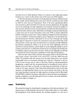
The next step in providing Questor with power is to mount
multipost barrier strips at various points on the robot’s plat-
form. Figure 3-4 shows what one of these strips looks like.
These barrier strips are very important because they allow the
42 CHAPTER THREE
FIGURE 3-3. Mounting brackets in place.
robot to be wired together with great ease; they also allow you
to remove individual components from the robot without
disturbing others. Most of Questor’s electrical components
use barrier strips.
For now you need only three barrier strips: two 2-post and
one 8-post. These two 2-post terminals are permanently
mounted on the platform near where the motorized wheel
post protrudes through the platform; the exact location is of
little importance. The third 8-post strip will be temporarily
mounted at the center of the rear edge of the robot’s platform.
It will be removed later for use in the remote control system.
WIRING PLATFORM
Now that the power supply and barrier strips are mounted they
must be wired together using 18-gauge wire. This wire will be
used now and throughout the robot. Figure 3-5 shows a graphic
representation of how the platform is wired. When you look at
Fig. 3-5, you will notice that all the wires used are either red or
black. The red wire represents all the wires that will eventually
be connected to the positive pole of the power supply, and the
black to the negative pole. While Fig. 3-5 is rather straightfor-
ward, a few things must be noted before wiring can begin.
First, the red and blue wires coming from each of the
motorized wheels must be connected to their barrier strips. The
wires from each wheel are too short and must be extended
POWER SUPPLY AND TEMPORARY CONTROL BOX 43
FIGURE 3-4. Multipost barrier strip.
using one 6-inch red and one 6-inch black wire for each
wheel. Use twist caps or solder the red extender wire to the
red wire of the motorized wheel and the black to the blue
wire. To connect the extended wire to the barrier strips, twist
both wires loosely together and push them up and out of the
post of the motorized wheel. This post leads to the inside of
the lower framework where the barrier strips are placed.
Connect the wire to two of the screw posts on the same side
of the strip. Refer to Fig. 3-5 for the exact connections.
Wiring the two 6-volt batteries together is made somewhat
difficult because of the small size of the battery post. Instead
44 CHAPTER THREE
FIGURE 3-5. Platform wiring diagram.
of trying to solder the connecting wire to the battery post, I
elected to use what is called a crimp kit. A crimp kit enables
you to attach special ends to the wires that allow them to be
wired together easily. Figure 3-6 shows the different ends
available and the crimping tool.
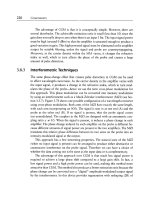
As illustrated in Fig. 3-7, the batteries are not only wired
together but to other components. Two of these are charging
plugs that come with the batteries. Also wired between the
two batteries is an SPST (single-pole, single-throw) switch.
This switch serves two functions: First, it is the main on/off
switch for Questor; and two, it separates the batteries when
they are being charged (the switch is in the off position at this
time). Make sure that you use lengths of wire long enough to
allow the charging plugs and switch to reach the rear of the
platform where they will be mounted later; for now you can
tape the components securely to the platform.
Once you have wired the platform, use the charging plugs
and charge the batteries. While the batteries are charging, it
takes about 36 hours, you can construct the temporary control
box used to control Questor.
TEMPORARY CONTROL BOX
Before you begin to assemble the temporary control box, a
brief explanation of how it functions is in order. To begin, the
two 6-volt batteries have been wired together to give Questor a
12-volt power source. This power source is then wired to two
potentiometers, one for each motorized wheel, within the con-
trol box. These pots as they are commonly called, are a type of
variable resistor that lowers or raises the voltage coming from
the batteries. The pots are used to control the speed of each
motorized wheel.
The lowered or raised voltage passes into two double-
pole, double-throw (DPDT) switches, again one switch for
each motorized wheel. The DPDT switches are actually two
switches in one, hence the term double in their description.
To reverse the direction of a dc electric motor, you must
POWER SUPPLY AND TEMPORARY CONTROL BOX 45
46 CHAPTER THREE
FIGURE 3-6. Crimp kit.
change the polarity of the wires leading to the motor. For
example, if the right terminal of the motor is connected to
the positive terminal of the power source, and the left to the
negative, the motor will run clockwise. Exchange the leads
so the right lead is negative and the left positive and the
motor will run counterclockwise, or in reverse. The DPDT
switch does all this internally so all you do is flip the switch
up or down to change the direction of the motor. Also
included in these switches is a center on/off position where
no power goes to the motor.
After passing through the DPDT switch the voltage reaches
one of the two motorized wheels on the robot’s platform, and
depending on the position of the switch the motor will run
POWER SUPPLY AND TEMPORARY CONTROL BOX 47
FIGURE 3-7. Battery wiring diagram.