Control of Redundant Robot Manipulators - R.V. Patel and F. Shadpey Part 4 pptx
Bạn đang xem bản rút gọn của tài liệu. Xem và tải ngay bản đầy đủ của tài liệu tại đây (229.69 KB, 15 trang )
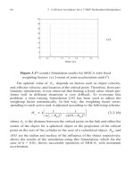
36 3 Collision Avoidance for a 7-DOF Redundant Manipulator
represent the arm and its environment. Colbaugh et al . [14] addressed this
problem for a planar manipulator. The obstacles were represented by circles
surrounded by a Surface of Influence (SOI), and the links were modeled by
straight lines. A redundancy-resolution scheme was proposed to achieve
obstacle avoidance. This approach was extended to the 3-D workspace of a
7-DOF manipulator in [75], [71],
[24].
In [75] and [71] the manipulator
links are represented by spheres and cylinders and the objects by spheres.
Although this method is convenient for spherical or bulky objects, it results
in major reduction of the workspace when dealing with slender objects.
Moreover, the
method is
not capable of
dealing with task
s involving pass-
ing through an opening. Glass et al. [24] proposed a scheme that considered
an application to remote surface inspection. This application requires the
robot to
pass through circular or rectan
gular openings for inspecti
on of a
space structure, such as the International Space Station. However,
they
made the restrictive assumption of having an infinite surface with one
opening which reduces the workspace of the robot. For instance, this
scheme does
not permit
an
“elbow” to back
into another
opening. More-
over, the arm used in their experiment, the Robotics Research Corporation
7-DOF arm (RRC), is modeled as a series of four straight lines connecting
joints one, three, and five. The thickn
ess of the links is considered via a
“buffer” region in the openings. This simplified model would not be appro-
priate for an arm with a more complex geometry such as the one used in the
research described
in this paper.
A simplified geometrical model for links of industrial manipulators rel-
evant to the study of collisions either with each other or with objects in the
workspace is the
cylinder. Also,
the cylinder is
a
very appropriate primitive
for modelling many objects in the workspace such as rods, mesh structures,
openings, etc., without much loss of the available workspace.
In Section 2, we focus on the special cases of sphere-sphere, sphere-
cylinder, and cyli
nder-cyli
nder collision detection and distance calcula-
tions. Considering the importance of cylinder-cylinder collision detection
and also its complexity, a novel method of detecting collisions between two
cylinders
using the n
otion of dual vectors and
angles is presented.
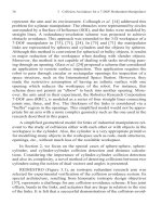
REDIESTRO
(Figure 3.1),
an isotropic redundant research a
rm
was
selected for experimental verification of the collision avoidance system. Its
special architecture, resulting from kinematic isotropic design objectives
[57], represents a challenge for any collision-avoidance scheme: It has joint
offsets, bends in the links, and actuators that are large in relation to the size
of the links. It is felt that a successful demonstration of the collision-avoid-
3.2
Primitive-
Based
Collision
A
voidance
37
ance scheme on such an arm provides confidence that the system can be
developed and applied to other more conventional (i.e., commercial) 7-
DOF manipulator designs. Section 3 extends the redundancy-resolution
module to the 3D workspace of REDIESTRO. It also describes the incorpo-
ration of different additional tasks into the redundancy-resolution mod-
ule. Simulation r
esults to study the feasibility
of
the
proposed
scheme as
well as effects of different parameters are given. Section 4 presents the
experimental evaluation of the collision- avoidance scheme using REDI-
ESTRO.
Figure 3.1 Perspective view of REDIESTRO
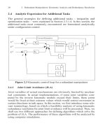
3.2 Primitive-Based Collision Avoidance
Collision avoidance for stationary and moving objects is achieved by
introducing an inequality constraint (see section 2.4.2) as the additional
task in the configuration control scheme for redundancy resolution. The
idea is to model the links of the manipulator and the objects by primitives
such as spheres and cylinders. The major components of the proposed
scheme are outlined below:
• Collision detection/prediction: For those objects (sub-links) that
can potentially collide, determine the critical distance , i.e.,
the distance from a critical point of the arm to that of the object.
The critical points associated with the manipulator and the
obstacles are denoted by and with position vectors and
, respectively.
• Critical direction detection: For any pair of critical points
and
, determine the critical direction,
denoted
by
, a unit
vector directed from to .
• Redu
ndancy re
soluti
on:
Formulate an additional task
and use
configuration control to inhibit the motion of the point
towards al
ong
.
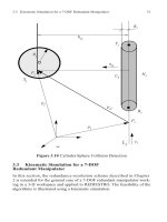
3.2.1Cylinder-Cylinder Collision Detection
In order to determine the relative position of two cylinders, first the rel-
ative layout of their axes needs to be established. The axes of the cylinders
being directed lines in three dimensional space, we resort to the notion of
line geometry. Specifically, with the aid of dual unit vectors, (or line vec-
tors), and the dual angles between skew lines, we categorize the relative
placement of cylinders and thus determine the possibility and the nature of
collisions between the two cylinders in
question.
We consider each cylinder to be composed of three parts, the cylindri-
cal
surface plus the two
circular
disks
as the top and the
bottom of the
cylin-
der. Four
points along the axis
of each cylinder
are of interest (see
Figure 3.2), namely, , , , and . The point is any point of refer-
ence along
the line. The
points
and
with posit
ion
vectors
and
,
respectively, are the centers of the bottom and top of the cylinder, and is
h
ij
P
i
c
P
j
c
p
i
c
p
j
c
P
i
c
P
j
c
u
ij
P
i
c
P
j
c
P
i
c
P
j
c
u
ij
L
i
C
i
P
i
B
i
T
i
H
i
P
i
B
i
T
i
b
i
t
i
H
i
38 3 Collision Avoidance for a 7-DOF Redundant Manipulator
3.2 Primitive-Based Collision Avoidance 39
the foot of the common normal of the two lines and on . To avoid
ambiguity for the choice of the top and bottom of the cylinder, we can
always choose and in such away that the vector points along
, with , being a unit vector defining the direction of the cylinder axis
(see Figure 3.2). Each of ,, and , can alternatively be defined
through their line coordinates with respect to the reference point ,
namely,
(3.2.1)
(3.2.2)
(3.2.3)
It should be noted that for a given cylinder , the scalars and are
known and fixed values.
3.2.1.1Review of Line Geometry and Dual Vectors
A brief review of dual numbers, vectors, and their operations, relevant
to our problem is provided in this section. A more detailed discussion can
be found in [4], [90], [95]. A line can be defined via the use of a dual
unit vector also called a line vector:
(3.2.4)
where , and , and is the dual unity which has the
property that . Here, defines the direction of , while the
moment of with respect to a self-understood point O , namely,
(3.2.5)
with p being the vector directed from O to an arbitrary point P of .
Moreover, e and m are called the primal and dual parts of .
L
i
L
j
L
i
B
i
T
i
B
i
T
i
e
i
e
i
B
i
T
i
H
i
P
i
b
i
p
i
b
i
e
i
+=
t
i
p
i
t
i
e
i
+=
h
i
p
i
h
i
e
i
+=
C
i
b
i
t
i
L
e
ˆ
e m+=
e
T
e 1= e
T
m 0= 0
2
0= eLm
L
mp
e
=
L
e
ˆ
Figure 3.2 Cylinder representation, basic notation.
Now, let
and
, be two lines. Their
dual angle is defined as
(3.2.6)
where isthe projected angle between and , and is the distance
between and . Furthermore,
(3.2.7)
(3.2.8)
Hence, t
he
dual
angle
uniquely det
er
mines the relative la
yout of the
two
lines and in space. Furthermore, the following relations that are in
exact
anal
ogy with real v
ectors can be veri
fied:
(3.2.9)
(3.2.10)
L
i
L
j
ˆ
ij
ij
h
ij
+=
ij
e
i
e
j
h
ij
L
i
L
j
ˆ
ij
si
n
ij
h
ij
ij
co
s
+sin=
ˆ
ij
cos
ij
cos h
ij
ij
sin
–
=
ˆ
ij
L
i
L
j
ˆ
ij
cos e
ˆ
i
e
ˆ
j
=
ˆ
ij
sin e
ˆ
i
e
ˆ
j
n
ˆ
ij
=
40 3 Collision Avoidance for a 7-DOF Redundant Manipulator
3.2
Primitive-
Based
Collision
A
voidance
41
where is the dual vector representing the line that coincides with
the common normal of and , and with the same direction as that of the
vector from to , namely , where
(3.2.1
1)
and . Hence, equations (3.2.11)
uniquely determine the dual angle subtended by the two lines. Three
diff
erent
possibili
ties for the layout of two di
sti
nct
li
nes
and
exist as
explained below:
• (A) Non-Parallel and Non-Intersecting Lines: is a proper
dual number,
i.e.,
,
wit
h
,
1 and
• (B) Intersecting Lines:
is a real number
,
(its dual part
is
zero), i.e., , with , 1 and .
• (C) Parallel Lines: is a pure dual number, (its primal part is
zero), i.e., , with , 1 and .
Now, for two cylinders and to collide, one of the three cases dis-
cussed below must occur:
• (1) Body-Body Collision: This situation the most likely one
is shown in Figure 3.3 , where two cylindrical bodies of an object
intersect.
• (2) Base-Body Collision: The cylindrical body of one cylinder
collides with one of the two circular disks of the other cylinder
.
• (3) Base-Base: One
of the
circular
disks of one cylinder collides
with a circular disk of another cylinder.
(A) C
YLINDERS WITH NON-PARALLEL AND NON-INTERSECTING AXES
In order to characterize the types of possible collisions for two cylin-
ders whose major axes are represented by and , that are non-parallel
n
ˆ
ij
N
ij
L
i
L
j
H
i
H
j
n
ˆ
ij
n
ij
n
˜
ij
+=
n
ij
h
j
h
i
–
h
j
h
i
–
=
n
˜
ij
n
ij
h
i
n
ij
h
j
==
ˆ
ij
L
i
L
j
ˆ
ij
ij
k k 0= h
ij
0
ˆ
ij
ij
k k 0= h
ij
0=
ˆ
ij
ij
k = k 0= h
ij
0
C
i
C
j
L
i
L
j
and non-intersecting, the following steps are taken:
(a) First we need to determine the location of the points along and
along , i.e, the feet of the common normal on the two lines. This can
be done by determining the scalars and , as given below:
(3.2.12)
(3.2.13)
with and .
(b) Now, if , then collision is not possible.
(c) If , then collision is possible, as explained below:
• (A-1)
1
If
and
,
then we
have a
body-body
collision and the critical points and on the axes are and
, respectively (Figure 3.3), with the critical direction being
.
• (A-2) If only one of the points or lies outside of its
corresponding cylinder, then, we may or may not have a collision.
However, if the two cylinders collide, then this has to be in the
form of a base-body collision only, (Figure 3.4). As an example,
in order to determine the critical points and the critical direction,
we assume that lies inside with lying outside . The
crit
ical point
of
wil
l thus be one
of the tw
o points
or
, whichever lies closer to . Moreover, the critical point
of the cylinder is the projection of on . If is the
1.
In this no
tation, the letter
indica
tes
the layou
t of th
e
axes of th
e
two
cylinders and the number indicates the type of collision.
H
i
L
i
H
j
L
j
h
i
h
j
h
i
p
i
p
j
–e
j
ij
e
i
–cos
2
ij
sin
-
=
h
j
p
j
p
i
–e
i
ij
e
j
–cos
2
ij
sin
=
h
i
p
i
h
i
e
i
+= h
j
p
j
h
j
e
j
+=
h
ij
R
i
R
j
+
h
ij
R
i
R
j
+
b
i
h
i
t
i
b
j
h
j
t
j
P
i
c
P
j
c
H
i
H
j
n
ij
H
i
H
j
H
i
C
i
H
j
C
j
P
j
c
C
j
B
j
T
j
H
j
P
i
c
C
i
P
j
c
L
i
p
j
c
42 3 Collision Avoidance for a 7-DOF Redundant Manipulator
3.2
Primitive-
Based
Collision
A
voidance
43
position vector of , we have
(3.2.14)
where is the vector connecting to . We thus consider that
a collision occurs, whenever the following inequality is satisfied
It should be noted that the above inequality gives a conservative
prediction of collision between the base and the body of the two
cylinders. In this manner, we implicitly assume that the base of
the cylinder
is not a
simple circular
disk, but, a fictitious semi-
sphere of the same radius. The critical direction for
becomes
(3.2.15)
Case (A-2)
above can
lead to instability
in the redundancy
resolution scheme if the two lines are almost parallel. In this
special situation, the location of the critical points on the two
lines ca
n
go through major change
s for
sma
ll
cha
nges
in the angle
made by them as shown in Figure 3.5. To remedy this “ill-
conditioning”, we inhibit the motion of two points of the line
towards their corresponding projections on whenever the two
lines are almost parallel. This is achieved by identifying two
critical directions one for each end of for the redundancy
resolution scheme.
• (A-3) If both and lie outside their corresponding cylinders,
then we
may have
a base-base collision, an
d the critical point
s
and direction are determined as explained below (Figure 3.6):
D
eno
te by
the set of distances of
and
to
and
,
i.e.
P
j
c
p
i
c
p
i
p
˜
j
c
e
i
e
i
+=
p
˜
j
c
P
j
c
P
i
p
i
c
p
j
c
– R
i
R
j
+
u
ij
C
i
u
ij
p
j
c
p
i
c
–
p
i
c
p
j
c
–
=
ij
L
i
L
j
C
i
H
i
H
j
d
k
B
i
T
i
B
j
T
j
Figure
3.3
(A-1) Body-Body collision (non-
parallel
and
non-int
ersecti
ng
axes)
Figure 3.4 (A-2) Base-Body Collision (non-parallel and non-intersecting
axes)
(3.2.16)
d
1
b
i
t
j
– d
2
b
i
b
j
–==
d
3
t
i
t
j
– d
4
t
i
b
j
–==
44 3 Collision Avoidance for a 7-DOF Redundant Manipulator
3.2 Primitive-Based Collision Avoidance 45
Figure 3.5 Near Parallel axes
and
,
then w
e
have a base-base
collision if
. Once again,
the foregoing
prediction
is conservative, as it assumes two semi-spherical base bodies
attached to the ends of the cylinders, rather than the simple
ci
rcu
lar disks.
(B) C
YLINDERS WITH INTERSECTING AXES
In order to characterize a collision between two cylinders with inter-
secting axes, we first project the end-points and of the cylinder
onto the line and denote the projected points by and . Con-
versely, we project
the
points
and
of the cylinder
onto the line
and
denote the projected points by
and
. Position
vectors of the fore-
going four points will take on the form:
d
c
min d
1
d
2
d
3
d
4
d
c
R
i
R
j
+
B
i
T
i
C
i
L
j
B '
j
T '
j
B
j
T
j
C
j
L
i
B '
i
T '
i
Figure 3.6 (A-3) Base-Base Collision (non-parallel and non-intersecting
axes)
(3.2.17)
with
(3.2.18)
• (B-2) If any one of the following four conditions holds, then we
have a base-body collision, and the critical direction is a unit
vector pointing along a vector
joining the corresponding critical
points, (F
igure
3.7),
b '
i
p
i
b'
i
e
i
t '
i
+ p
i
t'
i
e
i
+==
b '
j
p
j
b'
j
e
j
t '
j
+ p
j
t'
j
e
j
+==
b
'
i
p
i
b
j
–e
i
t'
i
– p
i
t
j
–e
i
–==
b'
j
p
j
b
i
–e
j
t'
j
– p
j
t
i
–e
j
–==
46 3 Collision Avoidance for a 7-DOF Redundant Manipulator
3.2
Primitive-
Based
Collision
A
voidance
47
(3.2.19)
• (B-3) If none of the foregoing conditions is satisfied, then we do
not have a base-body collision. However, we may have a base-
base collision. The procedure
for
base-base collision detection for
a pair of intersecting lines is similar to that of case (A-3)
explained earlier
(Figure 3.8).
Figure 3.7 (B-2) Base-Body Collision (intersecting axes)
(C) CYLI
NDERS WITH
P
ARALLEL
A
XES
For the special case of two parallel lines and for which an infi-
nite number of common normals exist, we resort to a unique definition for
one common normal lying closest to the origin [4] see Figure 3.9).
If the
line
passes through the points
and
of
and
(with
and
being the closest points of the two lines to the origin), then the dual rep-
resentation of is given as
b
i
b'
i
t
i
andb'
i
b
i
– R
i
R
j
+
b
i
t'
i
t
i
andt'
i
t
i
– R
i
R
j
+
b
j
b'
j
t
j
and b '
j
b
j
– R
i
R
j
+
b
j
t'
j
t
j
andt'
j
t
j
– R
i
R
j
+
L
i
L
j
N
ij
H
i
H
j
L
i
L
j
H
i
H
j
N
ij
(3.2.20)
Figure 3.8 (B-3) Base-Base Collision (intersecting axes)
where and are the position vectors of the points and , respec-
tively, and is the distance between the two lines.
If , then the two cylinders do not collide. However, if
, then, depending on the location of the cylinders along their
axes relative to each other,
two sp
ecial cases
of body-body (C-1) and base-
base (C-3) collisions can occur:
• (C-1) If , and the projection of either or on
is between and , then we have a body-body collision.
As in the case of near
-parallel axes mentioned in (A-3), to avoid
ill-conditioning, we specify two critical directions, one for each
end of (Figure 3.5).
n
ˆ
ij
h
j
h
i
–
h
ij
h
i
h
j
h
ij
+=
h
i
h
j
H
i
H
j
h
ij
h
j
h
i
–=
h
ij
R
i
R
j
+
h
ij
R
i
R
j
+
h
ij
R
i
R
j
+ B
i
T
i
L
j
B
j
T
j
C
i
48 3 Collision Avoidance for a 7-DOF Redundant Manipulator
3.2 Primitive-Based Collision Avoidance 49
• (C-3) If (C-1) is not satisfied, but , then we obtain
the distance between the end points of the two cylinders, as in the
(A-3) above (Figure 3.9).
3.2.2 Cylinder-Sphere Collision Detection
This case is simpler than that of cylinder-cylinder collision detection.
Figure 3.10 shows the basic layout used for collision detection of the cylin-
der and the sphere . The notation used for the cylinder is the same as
in Section 3.2.1. The sphere is identified by the location of its center
and its radius. The first step is to determine if there is a risk of collision.
The point on line is determined by projecting the center of the sphere
on ,
(3.2.21)
where is defined as . The critical distance is given by
Now, if
, there
is no risk of collision. If
,
then
the following cases can occur:
• If
and
lies inside the cylinder
, then the
cylinder and the sphere are in collision and the critical points and
critical direction are defined by
(3.2.22)
(3.2.23)
(3.2.24)
• If and lies outside the cylinder , then we
may o
r may not have
a collision. The critical point on the line
is either or depending on which is closer to . Let us
h
ij
R
i
R
j
+
C
i
S
j
S
j
P
j
H
i
L
i
L
i
h
i
p
ij
e
i
e
i
p
i
+=
p
ij
P
i
P
j
h
ij
h
ij
p
j
h
i
–=
h
ij
R
i
R
j
+ h
ij
R
i
R
j
+
h
ij
R
i
R
j
+ H
i
C
i
u
ij
p
j
h
i
–
p
j
h
i
–
=
p
i
c
h
i
R
i
u
ij
+=
p
j
c
p
j
R
j
u
ij
–=
h
ij
R
i
R
j
+ H
i
C
i
L
i
B
i
T
i
H
i
Figure 3.9 (C-3) Base-Base Collision (parallel axes)
assume that is the closer point to . The critical distance
is given by . Now, if , there is no
risk of collision; otherwise, there is a collision and the critical
points and direction are calculated by replacing with in
equations (3.2.22) through (3.2.24). It has to be mentioned that
the foregoing inequality gives a conservative prediction of
collision between the sphere and the cylinder. In this manner, we
implicitly assume that the base of the cylinder is not a simple
circular disk, but a fictitious semi-sphere of the same radius.
3.2.3 Sphere-Sphere Collision Detection
This is the simplest case among the three collision-detection schemes
presented. The critical distance is the distance between the centers of
the two spheres. If , then there is no risk of collision; other-
wise, the two spheres are in collision.
B
i
H
i
h
ij
h
ij
p
j
b
i
–= h
ij
R
i
R
j
+
h
i
b
i
h
ij
h
ij
R
i
R
j
+
50 3 Collision Avoidance for a 7-DOF Redundant Manipulator