Control of Redundant Robot Manipulators - R.V. Patel and F. Shadpey Part 6 pps
Bạn đang xem bản rút gọn của tài liệu. Xem và tải ngay bản đầy đủ của tài liệu tại đây (759.64 KB, 15 trang )
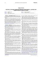
Figure 3.17 (contd.) Simulation results for MOCA with fixed
weighting factors: (c) 2-norm of joint accelerations (rad/s
2
)
The optimal value of depends on factors such as object velocity,
end-effector velocity, and location of the critical point. Therefore, from pre-
liminary simulations, it was observed that finding a fixed value which per-
forms well in different situations is very difficult. To overcome this
problem, a time-varying formulation [14] has been used to adjust the
weighting factor automatically. In this way, the weighting factor corre-
sponding to each active task is adjusted according to the following scheme:
(3.3.16)
where is the distance between the critical point on the link and either the
center of the object for a spherical object or the projection of the critical
point on the axis of the cylinder in the case of a cylindrical object. and
are the radi
us and
surface of
the influence
of the object respectively
.
shows the results of the simulation using this formulation, which for the
case of
k = 0.01, shows successful operation of MOCA, with
minimum
acceleration.
0 0.5 1 1.5 2 2.5 3 3.5 4
0
5
10
15
20
25
30
35
40
()
time (s)
W
C
W
c
k
1
d
c
R
O
–
2
1
SOI R
O
–
2
–
=
d
c
R
O
SOI
(c)
66 3 Collision Avoidance for a 7-DOF Redundant Manipulator
3.3
Kinemati
c Si
mul
ati
on for a 7-DOF Redun
dant
Manipulator
67
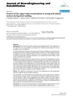
Figure 3.18 MOCA simulation results for time-varying weight factors:
(a) critical distance (mm); (b) 2-norm of joint velocities (rad/s)
- - - , ___ , (obstacle’s radius
= 70 mm and SOI = 100 mm)
k 100= k 1= k 0.01=
0 0.5 1 1.5 2 2.5 3 3.5 4
60
70
80
90
100
110
120
130
140
150
Critical Distance
time (s)
0 0.5 1 1.5 2 2.5 3 3.5 4
0
0.05
0.1
0.15
0.2
0.25
0.3
0.35
0.4
0.45
2-Norm of the Joint Velocities
time (s)
(b)
(a)
Figure 3.18 (contd.) MOCA simulation results for time-varying
weight factors: (c) ; (d) 2-norm of joint accelerations (rad/s
2
)
0 0.5 1 1.5 2 2.5 3 3.5 4
0
0.5
1
1.5
2
2.5
3
x 10
-3
W
c
time(s)
0 0.5 1 1.5 2 2.5 3 3.5 4
0
5
10
15
20
25
time (s)
W
c
(c)
(d)
68 3 Collision Avoidance for a 7-DOF Redundant Manipulator
3.4
Experimental
Evaluation
using
a 7-DOF Redundant
Manipulator
69
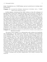
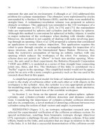
Figure 3.19 General block diagram for the hardware demonstration
3.4 Experimental Evaluation using a 7-DOF Redundant
Manipulator
The main objective of these experiments is to demonstrate the capabil-
ity of the redundancy resolution module in performing the main tasks (posi-
tion and orientation tracking) while using the extra degrees-of-freedom to
fulfill additional tasks (obstacle and joint limit avoidance) for REDI-
ESTRO. The general block diagram of the different modules involved in
the hardware experiment is shown in Figure 3.19 .
The three major modules are:
• The redundancy resolution module (RR)
• The robot and its associated control hardware and software
• The robot animation software: Multi-Robot Simulation (MRS)
system [9], [10], [77].
In order to distinguish between the performance of the robot controller
and the redundancy-resolution scheme, two separate control loops are
implemented, one at the Cartesian space level (including the RR) and the
MRS
SGI Workstation #2
Joint trajectory
SGI Workstation #1
Redundancy
Obstacle
Input
data
SUN Wo
rk
stat
io
n
VME cage
REDIESTRO
+
Environment
Processor
Boards
S bus-VME
adaptor
Serial and Parallel ports
Host for Real-
Resolution &
Avoidance
-Time OS
other at the low-level joint controller. In this way, the kinematic simulation
(including RR) running on an SGI workstation, generates the desired joint
trajectory and this trajectory is then transferred as the joint set points to the
VME-bus based controller to drive the robot’s PID joint controller.
An obstacle-avoidance system essentially deals with a complex envi-
ronment. There are many limitations in creating (modeling) a robot’s envi-
ronment such as space, material, equipment and financial limitations.
Creating a time-varying environment (as in the case of moving obstacles)
can be even more difficult. One solution to this problem is online transmis-
sion of a robot configuration to a workstation running a graphics visualiza-
tion of the arm (MRS). MRS serves as a virtual environment; the graphics
model of the robot mirrors the exact motion of the arm, and the environ-
ment can be modeled in the graphics program. This approach has two main
advantages:
• Any complex environment can be modeled with a desired
precision (including a time-varying environment)
• The risk of damage to the robot is reduced.
3.4.1 Hardware Demonstration
Three different scenarios were selected to verify the performance of the
obstacle-avoidance based redundancy-resolution scheme in executing the
following tasks: Position tracking, orientation tracking, stationary and mov-
ing obstacle collision avoidance, joint limit, and self-collision avoidance. In
each of these scenarios, one or multiple features were active at different
instants of execution. The sequence of steps undertaken in each case is as
follows:
1. Generate the joint trajectory with the redundancy resolution and
obstacle avoidance simulation.
2. Verify the result using MRS (e.g., are the obstacles avoided?).
3. Adjust parameters and repeat step 2 if necessary.
4. Position the stationary obstacles in the workspace.
5. Use the command trajectory to run the robot.
6. Record the joint history for further analysis
70 3 Collision Avoidance for a 7-DOF Redundant Manipulator
3.4
Experimental
Evaluation
using
a 7-DOF Redundant
Manipulator
71
For demonstration purposes, the stationary obstacles were built using
styrofoam and accurately positioned in the workspace. However, the mov-
ing object used in the second scenario was not constructed, instead, the per-
formance of the collision avoidance algorithm was observed using the
virtual models of the arm and the object in MRS.
3.4.2 Case 1: Collision Avoidance with Stationary Spherical Objects
In this scenario, the end-effector was commanded to move from its ini-
In the second scenario, the end-effector was commanded to keep its ini-
tial position to a final desired position: There were two stationary objects to
be avoided in the workspace. The orientation tracking task was not acti-
vated in this scenario; the orientation of the end-effector was not controlled.
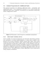
As an example, the plots of the commanded and actual joint values and
rates for the first joint are given in Figure 3.20 The set-point command tra-
jectory leads
the act
ual
joint
traject
or
y by
second which is
a typical
delay of a PID controller
(Fi
gure 3.20 a).
Fig
ure 3.
20 b and c show
the
desired and actual rates respectively. One can see that the actual rates fol-
low adequately the joint set-point command, except when the joint motion
is dominat
ed by stiction. The stiction effect
s also
explain the position error
at the end of the trajectory. Note that the PID controller only uses the rate
information (obtained by numerically differentiating the measured joint
angles) to provide damping. The oscillations shown in the PID rates are
probably due to underdamped tuning of the PID parameters and noise due
to numerical differentiation.
Figure 3.21 shows the snapshots of the arm motion. We can see that
without activating the obstacle avoidance feature (left sequence), the posi-
tion t
rajectory
is
followed perfect
ly, bu
t,
there are several collisions with
the obstacles. Figure 3.21 (right sequence) shows the successful operation
of position tracking and obstacle avoidance (visualization of the hardware
experiment). This scenario demonstrates the capability of the redundancy-
resolution module in performng position tracking and avoiding collisions
with obstacles.
3.4.3 Case 2: Collision Avoidance with a Moving Spherical Object
tial position while the orientation was changed. There was also a moving
object to be avoided. In order to satisfy the main task, six DOFs are
required, leaving one DOF for additional tasks. Figure 3.22 shows the
actual
joint angles
for joint
s
2 and 3. The
joints initi
ally start moving to
realize the commanded change of orientation, but this direction is reversed
0.1
Figure 3.20 Case 1: a) Joint 1 (deg); b) derivative of the joint set-point
command (deg/s); c) derivative of joint trajectory in hardware
experiment (deg/s).
for joint 2, at 0.9 second, when the arm starts to take evasive action to pre-
vent a collision. The joint-2 angle rapidly increases to a peak value of
degrees at 2 seconds. At 2.4 seconds, joint-2 quickly changes its direction
to respect the imposed joint limit (software limit to prevent self-collision)
of . It should be noted that there are more active additional tasks than
the available degrees of redundancy. However, task-prioritized formulation
of redundancy resoluti
on is
capable
of handl
ing
th
ese dif
ficult situat
ions
and leads only to a graceful performance degradation for the less prioritized
tasks (in this case position and orientation tracking).
Figure 3.23 left sequence (simulation results), shows that without any
0 5 10 15
−16
−14
−12
−10
−8
−6
−4
−2
0
0 5 10 15
−8
−6
−4
−2
0
2
4
6
8
0 5 10 15
−10
−8
−6
−4
−2
0
2
4
6
8
10
joint set-point command
hardware experiment
(a)
time (s)
(b)
(c)
time (s) time (s)
30
35
72 3 Collision Avoidance for a 7-DOF Redundant Manipulator
obstacle avoidance, joint-limit avoidance, and self-collision avoidance pro-
3.5
Conclusio
ns
73
visions, only the main task consisting of position and orientation tracking
can be successfully executed. However, there are multiple collisions with
objects and self-collision with the base. The right sequence of Figure 3.23
shows that by activating different modulesboth the main and additional
tasks
can be performed
simultaneously (visualization of the hardware
experiment).
3.4.4 Case 3: Passing Through a Triangular Opening
The environment was modeled by three cylindrical objects forming a
triangular opening. The end-effector trajectory was defined as a straight
line passing through this opening. Each obstacle is enclosed in a cylindrical
SOI. The left column in Figure 3.24 (a g) shows the motion (simulation
results) of the arm when the obstacle-avoidance module
is not
activated.
As
can be seen, the end-effector follows the desired trajectory; however, there
are multiple collisions between the links or the actuators and the obstacles.
By activating
the obstacle-avoidance module, both the end-effector trajec-
tory following and obstacle avoidance were achieved, as can be seen in the
right column of Figure 3.24 (h k) visualization of the hardware experi-
ment
.
3.5 Conclusions
In this chapter, the extension of the redundancy-resolution and obstacle-
avoidance module to the 3D workspace of REDIESTRO was addressed.
The
obstacle-avoidance algorithm wa
s modified to consider 3-D objects. A
primitives-based collision-avoidance scheme was described. This scheme is
general, and provides realism, efficiency of computation, and economy in
the use of the amount of free space around a redundant manipulator. Differ-
ent possible cases of collisions were considered. In particular, cylinder-cyl-
inder collision avoidance which represents a
c
omplex
case for a
collision-
detection scheme was formalized using the notion of dual vectors and
angles.
Before performing the hardware experiments using REDIESTRO to
evaluate the performance of the redundancy-resolution and obstacle-avoid-
ance modules, extensive simulations were performed using the kinematic
model of REDIESTRO. These simulations were aimed at a study of the fol-
lowing issues:
Figure 3.21 Collision avoidance with stationary spherical objects
Left sequence: simulation with no
obstacle avoidance provision
Right sequence: Visualization of
hardware experiment
74 3 Collision Avoidance for a 7-DOF Redundant Manipulator
3.5
Conclusio
ns
75
Fi
gur
e 3.22 Case
2: a) joint 2, b) joint 3 (degr
ees)
• Position and orientation tracking: Considering the complexity
of the
singular regions
existing in the 3D
workspace of a
7-DOF
manipulator, the singularity-robustness formulation of
redundancy was shown to be necessary in practical applications.
It
was
shown that by
a proper
selection (or a
time-varying
formulation) of , the weighting matrix of the singularity-
robustness task, the effect of this term on tracking performance
can be minimized.
• Performing additional task(s): Joint limit avoidance and
obstacle avoidance were implemented for REDIESTRO. It was
shown that the formulation of additional tasks as inequality
constraint
s,
may
result in
rapid
ch
ange in joint velocities causing
a large pulse in joint accelerations. In a practical implementation,
since the maximum acceleration of each joint would be limited,
such a commanded joint acceleration would result in saturation
of the actuators. A time-varying formulation of the weighting
matrix, , was proposed which successfully overcame this
problem.
0 1 2 3 4 5 6 7 8 9 10
−5
0
5
10
15
20
25
30
35
40
0 1 2 3 4 5 6 7 8 9 10
−20
0
20
40
60
80
100
joint set-point
com
mand
hardware experiment
(a)
(b)
time (s)
time (s)
W
v
W
c
• Fine tuning of control gains and weighting matrices
Figure 3.23 Collision Avoidance with moving spherical object.
Left (top to bottom): simulation
with obstacle avoidance (MOCA) inactive
Right:
V
is
uali
zati
on of ha
rd
ware
experiment.
76 3 Collision Avoidance for a 7-DOF Redundant Manipulator
3.5
Conclusio
ns
77
Figure 3.24 Passing through a triangular opening
Left seque
nce
: Simulation
with obstacle
avoidance inactive.
Right seque
nce
: Visualization of the hardware demonstration
with obstacle avoidance active
Three scenarios encompassing most of the redundancy-resolution and
obstacle-avoidance system features described in this chapter have been suc-
cessfully demonstrated on real hardware, i.e., the REDIESTRO manipula-
tor. Despite the geometrical complexity of REDIESTRO, the arm is
entirely modeled by decomposition of
th
e links and attach
ed actuators
into
sub-links modeled by simple volume primitives. Moreover, due to the com-
plex and unusual shape of REDIESTRO, it is believed that adapting the
algorithms to other manipulators will in general be simpler.
The current redundancy-resolution and obstacle-avoidance scheme pro-
vides an intelligently assisted tele-operation mode to the human operator in
that one only needs to specify the desired location and orientation of the
end-effector, and the system a
utomatically
takes
care of the
details of
motion control, configuration selection, and generalized collision avoid-
ance, including joint-limit and self-collision avoidance, in addition to colli-
sion with objects
in the workspace. H
owever,
at this stage
the
redundancy-
resolution scheme cannot handle situations where the manipulator comes in
contact with its environment. Further modification to the redundancy-reso-
lution scheme is needed in order for it to be used in a force or compliant
control scheme. This issue will be addressed in the next chapter.
78 3 Collision Avoidance for a 7-DOF Redundant Manipulator
CHAPTER 4 CONTACT FORCE AND COMPLIANT MOTION CONTROL
4.1 Introduction
Robotic tasks mainly fall into two categories: Constrained and uncon-
strained motions. During the initial stages of development in robotics, most
successful applications dealt with position control of unconstrained motion
of robot manipulators. The natur
e of these tasks does not require a robot to
come in contact with its environment (work piece). Spray painting is an
example of such a task in which the robot brings a spray gun near the sur-
face to be painted and then sweeps across the surface with a specified
velocity. Another example is that of seam welding. In some applications,
where a robot comes in contact with its environment (as in the case of mate-
rial handling), precise control of the interaction with the object is not
required. The problem that arises when using a position control scheme in a
constrained motion is that the robot-environment interaction forces are
treated as disturbances. The controller tries to reject these forces, and
hence, gives rise to larger interaction forces. The consequences of this are
saturat
ion,
instability, or ev
en
physical fai
lure
and damage to the robot and
the environment. Whitney [94] gives a historical perspective on robot force
control. Force control strategies have been mainly designed to use force
feedback sensory information.
Salisbury [60] proposed a stiffness control scheme. Raibert and Craig
[56] proposed a hybrid position-force control scheme. Yoshikawa [96],
McClamroch and Wang [45] proposed a method based on a constrained
dynamic model of a manip
ul
ator. Hog
an introduced the impedance control
idea in a series of papers in the mid-1980’s. In [30], he proposed the funda-
mental theory of impedance control which showed that command and con-
trol of
a vect
or such as position
or force is not
enough to control the
dynamic interactions between a manipulator and its environment. This
emphasizes the main problem of hybrid position-force control, i.e., its fail-
ure to recognize the importance of manipulator impedance. The impedance
control scheme overcomes this problem, but it ignores the distinction
between position and force controlled subspaces, and no attempt is made to
4C
ontact For
ce and Compliant Motion Contr
ol
R.V. Patel and F. Shadpey: Contr. of Redundant Robot Manipulators, LNCIS 316, pp. 79–117, 2005.
© Springer-Verlag Berlin Heidelberg 2005
80 4 Contact Force and Compliant Motion Control
follow a commanded force trajectory. Therefore, Anderson and Spong [1]
proposed a Hybrid Impedance Control (HIC) scheme, and Liu and Golden-
berg [40] introduced a robust HIC method.
The aforementioned methods can be divided into two main categories,
referred to as constrained motion [56], [96], [45], and compliant motion
[30], [1], [40] approaches. In the next sections, an outline of these
approaches is given. Note that the above mentioned algorithms are not
directly applicable to redundant manipulators. However, a careful review of
these algorithms gives guidelines for selecting force or compliant motion
control for redundant manipulators. Recent work has specifically concen-
trated on force o compliant motion control for redundant manipulators [69],
[53], [50], [29]. A class of nonlinear contact controllers is introduced in
[69]. Each controller consists of a nonlinear gain cascaded with a linear
fixed-gain proportional-integral (PI) force controller and proportional-
derivative (PD) compliance controller. In [53], an extended HIC scheme is
presented which achieves an inertial decoupling of the motion and force
controlled subspaces and internal motion control using a minimal parame-
trization of motion and force controlled subspaces and the null-motion
component. No experimental results are given. A force control scheme for
redundant manipulators is presented in [50] which decouples the motion of
the manipulator into task-space motion and internal motion while providing
for the selection of the dynamic characteristics for the motions. Hattori and
Ohnishi [29] describe a decentralized compliant motion control scheme for
redundant manipulators based on the concept of virtual impedance. The
manipulator is divided into several subsystems each of which performs
autonomously using virtual impedance and information from the end-effec-
tor subsystem. Simulation and experimental results are given for a redun-
dant planar manipulator.
In the remainder of this chapter, algorithms proposed for force and
compliant motion control of redundant manipulators are presented. Section
4.3.1 addresses the extension of configuration control at the acceleration
level. Section 4.3.2 introduces the Augmented Hybrid Impedance Control
(AHIC) scheme. The feasibility of this scheme with respect to performing
both the main and additional tasks is studied using a 3-DOF planar arm.
The AHIC scheme is then modified to cop with the uncontrolled self-
motion. The AHIC scheme with self-motion stabilization is presented in
4.3.3. An adaptive version of the AHIC scheme is presented in Section