Recent Advances in Mechatronics - Ryszard Jabonski et al (Eds) Episode 1 Part 2 pdf
Bạn đang xem bản rút gọn của tài liệu. Xem và tải ngay bản đầy đủ của tài liệu tại đây (2.48 MB, 40 trang )
3. Robot dynamics modeling
Forces that are caused by the motion of the whole platform can be de-
scribed as follows:
T
R
TT
RRR
T
RRR
TT
R
JymxmAfff
fffAJymxm
)()()(
)()(
1
321
321
θ
θ
−
=
⋅=
(4),(5)
where m is the robot mass, J
R
is the robot moment inertia, f
Ri
is the traction
force of each wheel.
Dynamic model for each wheel:
wiiw
rfnMcJ −=+
ωω
(6)
where J
w
is the inertial moment of the wheel, c is the viscous friction
factor of the omniwheel, M is the driving input torque, n is the gear
ratio and f
wi
is the driving force due to each wheel.
The dynamics of each DC motor can be described using the follow-
ing equations:
ikMbJ
ukRi
dt
di
L
extmmm
m
2
1
=++
=++
ωω
ω
(7),(8)
where u is the applied voltage, i is the current, L is the inductance, R is the
resistance, k
1
is the emf constant, k
2
is the motor torque constant, J
m
is the
inertial moment of the motor, b is the vicious friction coefficient, M
ext
is
the moment of an external load and
ω
m
is the angular speed of the motor.
By merging equations (2)-(8) we obtain a mathematical model of each es-
sential dynamic properties of mobile robot undercarriage.
4. Robot model
The trajectory of motion is described by a list of points, each with four
important parameters [x, y, v,
ω
]. From these points obtained needed vec-
tor of velocities [v
x
, v
y
,
ω
] by the Trajectory controller module. Inverse
kinematics is used to translate this vector into individual theoretically re-
quired velocities of wheels. Dynamics module is then used to compute in-
ertial forces and actual velocities of wheels. By means of Direct Kinemat-
ics module, these velocities are re-translated into the final vector of veloci-
ties of the whole platform. Simulator module obtains the actual performed
path of the robot by their integration.
The whole model [1] was designed as a basis for modeling of mobile robot
motions in order to analyze the impact of each constructional parameter on
its behavior. For this reason, there is not used any feedback to control the
T. Kubela, A. Pochylý
motion on a desired trajectory. This approach allows choosing key parame-
ters more precisely for better constructional design.
Fig. 2. Robot model in Matlab Simulink
In order to create this simulation model there was used software MATLAB
Simulink 7.0.1. The emphasis was laid particularly on its schematic clear-
ness and good encapsulation of each individual module. It has an impor-
tant impact on an extensibility of the model in the future in order to create
and analyzed other function blocks.
Fig. 3. Example of the impact of dynamic properties on a performed path of the
robot
Simulation modeling and control of a mobile robot with omnidirectional wheels
5. Design of the mobile robot
There was chosen a symmetric undercarriage with omnidirectional
wheels in order to simulate the behaviors, properties and characteris-
tics of the mobile robot. It was the starting point from the previous
year.
Fig. 4. OMR IV design – view on the whole system
6. Conclusion
This contribution summarizes a kinematical and dynamical model of the
mobile robot without a feedback (open-loop) simulated in Matlab Simulink
environment. The whole model was designed as a basis for motions mod-
elling of a mobile robot undercarriage in order to analyze its key factors
that influence the final motion and allow an optimal choice of these pa-
rameters which are required for a constructional proposal.
Published results were acquired using the subsidization of the Ministry of
Education Youth and Sports of the Czech Republic research plan MSM
0021630518 „Simulation modelling of mechatronic systems”.
7. References
[1] Kubela, T., Pochylý A., Knoflíček R. (2006) Dynamic properties mod-
eling of mobile robot undercarriage with omnidirectional wheels: Proceed-
ings of International Conference PhD2006, Pilsen, pp 45-46.
[2] Rodrigues, J., Brandao, S., Lobo, J., Rocha, R., Dias, J. (2005) RAC
Robotic Soccer small-size team: Omnidirectional Drive Modelling and
Robot construction, Robótica 2005 – Actas do Encontro Científico, pp
130-135.
6 T. Kubela, A. Pochylý
Environment detection and recognition system
of a mobile robot for inspecting ventilation ducts
1
A.Timofiejczuk, M. Adamczyk, A. Bzymek, P. Przystałka,
Department of Fundamentals of Machinery Design,
Silesian University of Technology, Konarskiego 18a
Gliwice, 44-100, Poland
Abstract
The system of environment detection and recognition is a part of a mobile
robot. The task of the robot is to inspect ventilation ducts. The paper deals
with elaborated methods of data and image transmission, image process-
ing, analysis and recognition. While developing the system numerous ap-
proaches to different methods of lighting and image recognition were
tested. In the paper there are presented results of their applications.
1. Introduction
Tasks of a system of environment detection and recognition (vision system
VS) of an autonomous inspecting robot, whose prototype was designed
and manufactured in Department of Fundamentals of Machinery Design at
Silesian University of Technology is to inspect ventilation ducts [2]. VS
acquires, processs and analyzes information regarding environment of the
robot. Results, in the form of simple messages, are transmitted to a control
system (CS) [3]. Main task of the vision system are to identify obstacles
and their shapes. The robot is equipped with a single digital color mini
camera, which is placed in front of the robot (Fig.1.) Two groups of proce-
dures were elaborated:
• procedures installed on a board computer (registration, decom-
pression, selection, recognition and transmission);
1
Scientific work financed by the Ministry of Science and Higher Education and
carried out within the Multi-Year Programme “Development of innovativeness
systems of manufacturing and maintenance 2004-2008”
• procedures installed on the operator’s computer (visualization, re-
cording film documentation).
Fig.1. Single camera is placed in front of the robot
All procedures of VS were elaborated within Matlab and C++, and operate
under Linux. Three modes of VS operation are possible [2] [3]:
• manual –images (films) are visualized on the operator’s monitor
and film documentation is recorded. The robot is controlled by an
operator. Image processing and recognition is inactive.
• autonomous – recorded images are sent to the operator’s computer
as single images (they are selected after decompression realized on
the board computer). Image processing and recognition is active.
• „with a teacher” – films are sent to the operator’s computer. Robot
is controlled by the operator. Realization of operator’s commands
is synchronized with activation of image and recognition proce-
dures. A goal of this mode is to gather information on robot con-
trol. The information is used in a process of self-learning that is in-
the middle of elaborating.
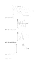
2. Image registration, transmission and visualization
Since duct interiors are dark, closed and in most cases duct walls are shiny
a way of lightening has a significant meaning [4]. Image recording was
preceded by examination of different lightening. Most important demands
were small size, low energy consumption. Several sources were tested
(Fig.2) (a few kinds of diodes, and white bulbs). As the result a light
source consisting of 12 diodes was selected (it is used in car headlights).
Image recording was performed by a set consisting of a digital camera and
(
520 TV lines, 0.3 Lux,
objective 2,8 mm, vision angle 96 degrees) and
frame grabber CTR-1472 (PC-104 standard). Film resolution is 720x576
A. Timoejczuk, M. Adamczyk, A. Bzymek, P. Przystałka
pixels in MPEG-4 compressed format [1]. Transmission is active in the
manual mode. In autonomous mode decompression and selection are per-
formed. An image is processed only in case a change in the robot
neighborhood occurred.
a) b) c) d)
Fig.2. Selected examples of light sources, a) white LED, b) blue LED, c) LED
headlamp, d) car headlight.
Only images transmitted to the operator’s monitor can be visualized. De-
pending on a mode the operator observes transmitted films (manual and
„with teacher” modes) or single decompressed images (autonomous
mode). Transmitted images are stored as a film documentation. Collecting
such documents is one of the main tasks of the robot [2].
3. Image processing and analysis
Two main approaches to image analysis were elaborated. A goal of the
first one was to extract some image features. Monochrome transformation,
reflection removal, binarization, histogram equalization and filtration were
applied. Results of these procedures were shown in Fig. 3.
Fig.3. Examples of images and results of their processing
Analysis procedures were applied to the images shown in Fig. 3. Results of
analysis are 5 features (shape factors and moments) calculated for identi-
fied objects. These features have different values for different duct shapes
and obstacles what makes it possible to identify them. However, per-
formed research shown that image recognition on the basis of these values
in case of composed shapes (curves and dimension changes) does not give
expected results. Moreover it requires that advanced and time consuming
Environment detection and recognition system of a mobile robot for inspecting
methods of image processing have to be applied. As the result of that an-
other approach was elaborated. Images were resampled in order to obtain
possible low resolution that was enough to distinguish single objects visi-
ble in the image (Fig. 4). These images were inputs to neural networks ap-
plied at recognition stage.
a) b) c) d)
Fig.4. Resolution resampling a) and c) 720x576, b) and d) 30x30
4. Image recognition
Image recognition was based on the application of neural networks that
were trained and tested with the use of images recorded in ducts of differ-
ent configuration (Fig.5).
[PP1]
Fig.5. Ventilation ducts used as test stage
A library of images and patterns was elaborated. As a result of a few tests
of different neural networks a structures consisting of several three layer
perceptrons was applied. Each single network corresponds to a distin-
guished obstacle (shape or curve). Depending on the image resolution a
single network has different numbers of inputs. The lowest number (shapes
are distinguishable) was 30x30 pixels. All networks have the same struc-
ture. It was established by trial and error, and was as follows: the input
layer has 10 neurons (tangensoidal activation function), the hidden layer
has 3 neurons (tangensoidal activation function) and the output layer has 2
neurons (logistic activation function). As training method Scaled Conju-
0 A. Timoejczuk, M. Adamczyk, A. Bzymek, P. Przystałka
gate Gradient Algorithm was used. For each network examples were se-
lected in the following way: the first half of examples – the shape to be
recognized and the second half of examples – randomly selected images
representing other shapes. This approach is a result of numerous tests and
gave the best effect.
It must be stressed that results of neural network testing strongly depend
on lightening and camera objective, as well as a number of examples and
first of all image resolution. Results of present tests made it possible to
obtain classification efficiency about 88%. Such low image resolution and
numbers of neurons in a single network required that 54000 examples had
to be used during network training. In order to increase the number of test-
ing images a few different noises were introduced to images.
5. Summary
The most important factor that influences recognition correctness is too
low resolution. However, its increase leads to non-linear decrease of a
number of examples necessary to network training. At present stage of the
research the application of cellular network is tested. One expects that out-
puts of these networks can be applied as inputs to the three layer percep-
tron. The most important is that these outputs seem to describe shapes
more precisely than shape factors and moments and simultaneously their
number is lower then the number of pixels of images with increased reso-
lution.
References
[1] M. Adamczyk: “Mechanical carrier of a mobile robot for inspecting
ventilation ducts” In the current proceedings of the 7th International
Conference “MECHATRONICS 2007”.
[2] W. Moczulski, M. Adamczyk, P. Przystałka, A. Timofiejczuk: „Mobile
robot for inspecting ventilation ducts” In the current proceedings of the
7th International Conference “MECHATRONICS 2007”.
[3] P. Przystałka, M. Adamczyk: “EmAmigo framework for developing
behavior-based control systems of inspection robots.” In the current
proceedings of the 7th International Conference “MECHATRONICS
2007”.
[4] A. Bzymek:”Experimental analysis of images taken with the use of
different types of illumination” Proceedings of OPTIMESS 2007
Workshop, Leuven, Belgium.
1Environment detection and recognition system of a mobile robot for inspecting
Calculation of robot model using feed-forward
neural nets
C. Wildner, J. E. Kurek
Institute of Robotics and Control Warsaw University of Technology
ul. Św. Andrzeja Boboli 8, 02-525, Warszawa, Poland
Abstract
Neural nets for calculation of parameters of robot model in the form of the
Lagrange-Euler equations are presented. Neural nets were used for calcula-
tion of the robot model parameters. The proposed method was used for
calculation of robot PUMA 560 model parameters.
1. Introduction
Mathematical model of industrial robot can be easily calculated using for
instance Lagrange-Euler equation [1]. However, it is very difficult to cal-
culate the real robots inertia momentums, masses, etc. Mathematical model
of industrial robot is highly nonlinear. In this paper for assignment of
model coefficients we will use neural nets. Neural nets can approximate
nonlinear functions. Neural model of robot has been built using only in-
formation from inputs and outputs of robot (i.e. control signals and joint
positions) and knowledge of model structure.
2. Lagrange-Euler model of robot
Mathematical model of robot dynamic with n degree of freedom can be
presented in the form of Lagrange-Euler equation as follows:
τθθθθθ
=++ )(),()( GVM
(1)
where
θ
∈
R
n
is a vector of generalized robot variable,
τ
∈
R
n
is a vector of
generalized input signal, M(
θ
)
∈
R
n×n
is inertia matrix of robot,
n
RV
∈
),(
θθ
is a vector of centrifugal and Coriolis forces and G(
θ
)
∈
R
n
is
a homogenous gravity vector with respect to the base coordinate frame.
Calculating the derivatives in the following way [1]:
p
p
T
Ttt
t
)()(
)(
−−
≅
θθ
θ
,
p
p
T
tTt
t
)()(
)(
θθ
θ
−+
≅ (2)
where T
p
denotes the sampling period, one can obtain the discrete-time
model of the robot based on (1) as follows:
)()]([)]([)]1(),([)1()(2)1( kkCkBkkAkkk
τ
θ
θ
θ
θ
θ
θ
θ
+
+
−
+
−
−
=
+
(3)
where k is a discrete time, t=kT
p
, and
)]([)]([
)]([)]([)]([
)]1(),([)]([)]1(),([
12
12
12
kMTkC
kGkMTkB
kkVkMTkkA
p
p
p
θθ
θθθ
θθθθθ
−
−
−
=
−=
−−=−
(4)
3. Neural model for robot
The set of three, three-layer feed-forward neural nets was used for calcula-
tion of unknown parameters A, B, C of model (3), fig. 1.
)(),( kk
τ
θ
θ
n n
(
k+ 1
)
N L
1
N L
2
L
N L
1
N L
2
L
N L
1
N L
2
L
A
B
C
z
-
1
θ
(
k-1
)
Fig. 1. The strukture of neural nets
Each net consists of 3 neuron layers: the first and the second layer is
nonlinear (NL
1
, NL
2
), and output layer is linear (L). A general neuron equa-
tion is as follows
)]([)( kvfky
=
(5)
where v is a generalized neuron input
∑
=
+=
h
i
ii
wkuwkv
1
0
)()( (6)
Calculation of robot model using feed-forward neural nets
and u
i
is input to the neuron, w
i
is input’s weight, w
0
is bias, and f(*) is a
transition function. Nonlinear neuron layer consists of neurons with sig-
moidal hyperbolic tangent transition function
]1,1[1
1
2
)(tansig)(
2
−∈−
+
===
−
y
e
vvfy
v
NL
(7)
and neurons in linear neuron layer have the following transition function:
constbbvvfy
L
=== )( (8)
We have assumed that the input signals to every layer are connected with
all neurons in this layer. Input signal to the nets is generalized robot vari-
able
θ
(k),
θ
(k–1). The following performance index was used for network
learning
∑ ∑
= =
−=
N
k
n
j
nnjj
dkkdJ
1 1
2
)],()([
2
1
)(
θθ
(9)
where
θ
nn
∈R
n
is an output vector of the network, d is the learning iteration
number, N is the length of learning data sequence. The backpropagation
method [2] were used for network learning.
4. Calculation of neural model
We have used the proposed method for calculation of the model parame-
ters of Puma 560 robot [1]. The robot has n=6 degree of freedom: six revo-
lute joints. Sequence of the learning data, input and output signals, had
length N=600. The robot had to follow the given reference trajectory in
time t=6 [sec] with T
p
=0.01 [sec]. For calculation of the learning data the
trajectory of every joint was set according to the following formula
)sin(
3
1
)(
,
tt
ir
=
θ
, i=1, ,6 (10)
Then, for network testing we have used another data. The reference testing
trajectory was as follows
)3sin(
2
1
)(
,
tt
it
=
θ
, i=1, ,6 (11)
Both reference trajectories for learning and testing of the network are pre-
sented in fig. 2, note that the trajectories values are given in degrees.
C. Wildner, J. E. Kurek
a. b.
Fig. 2. The reference trajectories: a) learning data output, b) testing data.
Neural nets for calculation of model (3) unknown parameters A, B, C, had
respectively 5, 4, 8 neurons in layers NL
1
and NL
2
. The number of neurons
in output layer L was equal to number of elements in matrices A, B, C, re-
spectively 6, 6 and 36. The results obtained after 2000 learning iterations
are presented in fig. 3 and in tab. 1. In fig. 3 the difference between the
reference trajectory
θ
r
and output of the neural network
θ
nn
is given in de-
gree. In tab. 1 maximal errors between
θ
r
and
θ
nn
are given.
Fig. 3. Difference between the reference trajectory
θ
r and output
θ
nn obtained
from neural model for the learning data after the learning process.
Tab. 1. Maximal errors after 2000 learning iterations
max
nnr
θθ
−
,
θ
r
(t)=sin(t)/3
Joint 1 2 3 4 5 6
0.0006 [°] 0.0008 [°] 0.0013 [°] 0.0029 [°] 0.0081 [°] 0.0039 [°]
The results of testing of the network are presented in fig. 5 and tab. 2. Dif-
ference between
θ
t
and
θ
nn
is shown in fig. 5. Maximal errors between
θ
t
and
θ
nn
are given in tab. 2.
Calculation of robot model using feed-forward neural nets
Tab. 2. Maximal errors for testing data
max
nnr
θθ
−
, {
θ
t
(t)= sin(3t)/2}
Joint 1 2 3 4 5 6
0.1687 [°] 0.2048 [°] 0.2732 [°] 0.6810 [°] 0.8188 [°] 0.7869 [°]
Fig. 5. Difference between the reference trajectory
θ
r and output
θ
nn obtained from
neural model for the testing data.
5. Concluding remarks
Neural nets were used for calculation of the Puma 560 robot model pa-
rameters. Neural nets learning is difficult to execute. From the results ob-
tained during learning process with the reference trajectory described by
equation (10) it follows that an average difference between output of the
robot and neural model after 2000 learning iterations was approximately
0.003 [deg]. For testing data with the reference trajectory described by (11)
we have obtained maximal difference between output of the robot and out-
put of the neural model approximately 0.5 [deg]. From the obtained results
it follows that it is possible to obtain a neural model of the robot based
only on robot outputs and inputs. We plan to use other techniques calcula-
tion of the neural nets.
References
[1] Fu K. S., Gonzalez R. C., Lee C. S. G., “Robotics, control, sensing,
vision, and intelligence”, McGraw-Hill Book Company, 1987.
[2] Osowski S., „Sieci neuronowe w uj
ęciu algorytmicznym”, WNT,
Warszawa, 1996.
[3] Wildner C., Kurek J. E., „Identyfikacja modelu robota za pomoc
ą re-
kurencyjnych sieci neuronowych – synteza układu sterowania robo-
ta”, XV Kraj. Konf. Automatyki KKA, Warszawa, Poland 2005.
6 C. Wildner, J. E. Kurek
EmAmigo framework for developing behavior-
based control systems of inspection robots
1
P. Przystałka, M. Adamczyk
Silesian University of Technology, Department of Fundamentals of Ma-
chinery Design, 18A Konarskiego Str., 44-100 Gliwice, Poland
Abstract
The paper deals with the implementation of the behavior-based control and
learning framework for autonomous inspection robots. The presented con-
trol architecture is designed to be used in the mobile robot (Amigo) for the
visual inspection of ventilation ducts. In this paper, various problems are
discussed including brief description of hardware components (PC-104
modules), low-level hard real-time operating system (RTAI), high-level
manual and autonomous mode control interface (Linux, KDE). The main
aim of this paper is to present the framework for rapid control prototyping
in the case of the inspection robot.
1. Introduction
Modern mobile robots are usually composed of heterogeneous
[WM1]
hard-
ware and software components. In a large amount of cases, during devel-
oping stage when a construction of a robot is still in an early development
phase, hardware and software components should allow rapid prototyping
of a control system. The proposed control architecture may be used either
in early development phase or in a final robot prototype. This work focuses
only on such key aspects as the hardware layout, low-level real-time op-
eration system and some software components implemented on the robot.
1
Scientific work financed by the Ministry of Science and Higher Education and
carried out within the Multi-Year Programme “Development of innovativeness
systems of manufacturing and maintenance 2004-2008”
The paper is organized as follows. Section 2 describes PC/104 embed-
ded modules and a real-time operating system as the core of the discussed
framework. There is also given remote control software enabling typical
capability of the robot. Finally, the paper is concluded in Section 3.
2. Control system architecture
This section describes the hardware layout and software components that
are necessary to make the general-purpose framework for developing vari-
ous control strategies of an inspection robot.
2.1 Hardware layout
As demonstrated in the related paper [1, 2, 3], the construction of the robot
has been modified from a four-legged walking robot (12 servo-
mechanisms) to a wheeled robot (at first with 4 and next with 6 stepper
motors). This was the main reason that PC/104 technology was chosen to
be used as the hardware platform. The main module of the hardware layout
is PC/104 motherboard with power supply DC/DC 5V. It is equipped with
300 MHz Celeron processor (Ethernet interface, USB 1.1, RS-232, PCI
bus), 512 MB RAM, 2 GB Flash.
Fig. 1. Main components of the inspection robot Amigo
The second component is DMM-32X-AT, a PC/104-format data acquisi-
tion board with a full set of analog and digital I/O features. It offers 32
analog inputs with 16-bit resolution and programmable input range;
250,000 samples per second maximum sampling rate with FIFO operation;
4 analog outputs with 12-bit resolution; user-adjustable analog output
ranges; 24 lines of digital I/O; one 32-bit counter/timer for A/D conversion
and interrupt timing; and one 16-bit counter/timer for general purpose use.
The last component is a high performance four channel MPEG-4 video
compressor that supports real-time video encoding. These modules are
P. Przystałka, M. Adamczyk
used to handle all the I/O data for the whole system and to calculate the
control parameters.
2.2 Hard real-time operating system
Real-time operating system (RTOS for short) has to provide a required
level of service in a bounded response time (e.g. a real-time process con-
trol system for a robot may sample sensor data a few times per second
whereas stepper motors must be serviced every few microseconds). A so-
called hard real-time system is one that misses no timing deadlines. The
authors considered such RTOS as: RTLinux [5], KURT [10], RTAI [4],
Windows CE [6], VxWorks [9]. Finally, RTAI was selected as extension
of standard Linux Kernel for the simple reasons that it offers extended
LXRT (hard-hard real time in user space) and is free of charge.
Fig. 2. Micro Kernel real-time architecture for the inspection robot Amigo
Figure 1 shows a diagram of the discussed operating system implemented
on the robot. Inter-process communication is provided by one of the fol-
EmAmigo framework for developing behaviorbased control systems of inspection
lowing mechanisms: UNIX PIPEs, shared memory, mailboxes and
net_rpc. In the first stage of the project only named pipes are applied. It
can be used to communicate real-time process between them and also with
normal Linux user processes.
Device RTAI FIFO (O_NONBLOCK)
Sensors /dev/dmm32x/sensors/sensor…
Actuators /dev/dmm32x/actuators/motor…
/dev/dmm32x/control/behaviour…
Controller
/dev/dmm32x/control/coordinator
In this way the access to every device connected to the robot may be sim-
ply available by putting/reading data into/from RTAI FIFOs. Moreover,
Embedded Debian Linux which is installed on the robot gives all the ad-
vantages of standard operating systems (TCP/IP, Wireless LANs, SSH,
NFS, SQL databases, C/C++, Python, Java application, etc.).
2.3 EmAmigo 3.14 – user interface
EmAmigo 3.14 application is a task-oriented interface for end users inter-
acting with the robot. It is implemented on the remote Linux-based host
using C++ and Qt libraries [11].
Fig. 2. EmAmigo 3.14 - KDE user interface of the Amigo robot
This application enables some typical capability of the robot: remote con-
trol by human operator (using keyboard or joypad controller), monitoring
0 P. Przystałka, M. Adamczyk
different robot parameters (robot states, real-time video footage), and gath-
ering data needed for learning behavior-based controller.
3. Conclusions
In this paper, the authors described the hardware and software framework
(free of charge for non-commercial purposes) that can be used for rapid
control prototyping of such mechatronic systems as mobile robots. Putting
together PC/104 technology and RTAI hard real-time operating system one
obtains a tool which is easy to adapt and easy to develop.
References
[1] Adamczyk M.: “Mechanical carrier of a mobile robot for inspecting
ventilation ducts” In the current proceedings of the 7th International Con-
ference “MECHATRONICS 2007”.
[2] Adamczyk M., Bzymek A., Przystałka P, Timofiejczuk A.: “Environ-
ment detection and recognition system of a mobile robot for inspecting
ventilation ducts.” In the current proceedings of the 7th International Con-
ference “MECHATRONICS 2007”.
[3] Moczulski W., Adamczyk M., Przystałka P., Timofiejczuk A.: „Mobile
robot for inspecting ventilation ducts” In the current proceedings of the 7th
International Conference “MECHATRONICS 2007”.
[4] The homepage of RTAI - the RealTime Application Interface for
Linux, 2006.
[5] FSM Labs Inc. First real-time linux, 2002.
[6] Microsoft. Windows CE .NET Home Page, 2002.
[7] Frederick M Proctor and William P Shackleford. Embedded real-time
Linux for cable robot control. In Proceedings of DETC'02 ASME 2002
2002.
[8] Steve Rosenbluth, Michael Babcock, and David Barrington Holt. Con-
trolling creatures with Linux. Linux Journal, November 2002.
[9] Wind River Systems. VxWorks 5.x, 2002.
[10] Kansas University. KURT: Real Time Linux, 1997.
[11] Trolltech: Leader in cross-platform C++ GUI software development
and embedded Linux solutions.
/>1EmAmigo framework for developing behaviorbased control systems of inspection
Simulation of Stirling engine working cycle
M. Sikora, R. Vlach
Institute of Solid Mechanics, Mechatronics and Biomechanics,
Faculty of Mechanical Engineering, Brno University of Technology,
Czech Republic,
Institute of Solid Mechanics, Mechatronics and Biomechanics,
Faculty of Mechanical Engineering, Brno University of Technology,
Czech Republic,
Abstract
This paper describes model of Stirling machines. The model will be used
for optimalization of power station. The power station consists of Stirling
engine and electric generator. The genetic algorithms can be used for iden-
tification parameters of engine.
1. Introduction
The engines with external heat inlet were never widespread in the past [3]
except steam engine. Nowadays, it is necessary to solve some global prob-
lems and to look for new alternative sources of energy.
The aim is a design of small combined heat and power unit which is driven
by Stirling engine. Achieving of good thermodynamically Stirling engine
efficiency represents relatively difficult optimizing task. The design of
accurate thermal model is very important. We cannot neglect many heat
losses, so the theory of ideal cycles is not usable. The computational mod-
els dividing working gas volume into two or three sub-areas are not too
accurate. The engine dividing into many volume elements (final volumes
method) makes better results. There are few simplifications of gas proper-
ties in the model. The above mentioned method of calculation does not
achieve the CFD accuracy. However, this model is faster and more suitable
for future optimalization of engine parameters.
2. Thermal model characteristic
The properties of the developed Stirling engine model (
γ
-modification) are
as follows:
• Numerical model is used. It is able to simulate non-stationary and
transient processes.
• The ideal gas, for which the state equations are applied [2], are
considered as working medium.
• The friction and inertial forces are not considered in working gas.
• The leakages of the gas from engine working part are not consid-
ered.
• The pressure losses due to displacement of the working gas are
omitted, the same holds for the gas warming due to friction.
• The model so far does not include the re-generator of the working
gas temperature.
• The engine is divided into volume elements for thermal processes
modelling (final volumes method), see fig. 1
3. Numerical calculation system of this model
The Stirling engine model is represented by system of several non-linear
differential equations and by another auxiliary relation. The regular divid-
ing of the engine makes possible using of the matrix system of many vari-
ables. The main calculation is solved by numerical integration with fixed
time step [4]. For calculation of some variables we must use results from
previous step because actual value has not yet been calculated. Errors due
to this fact are negligible at sufficiently small time step.
Three related problems are solved in this iteration calculation:
1) The behaviour of working gas temperatures and pressure. The
pressure value is used for output power determination.
2) The determination of working gas flow among gas elements. It is
solved by using other sub-iteration cycle.
3) We must still consider the thermal processes in solid parts of en-
gine in each solution step. The interaction of solid parts elements
is solved by thermal network method.
We consider also addition of electrical generator model. The whole model
is implemented in MATLAB software.
Simulation of Stirling engine working cycle
Fig. 1. Small sample Stirling engine division to elements
4. Simulations results
The input parameters correspond with dimensions and properties of Stir-
ling engine small real model. The values of some parameters have been
only estimated (e. g. heat transfer coefficients) and these parameters
should be verified by experiments.
Figure 2 show the time (and crank tilting angle) relations of torque, pres-
sure and temperatures of working gas in two crank movements. These
temperatures belong to elements: under the displacer, above displacer and
in working cylinder.
M. Sikora, R. Vlach
Figure 3 shows distribution of temperature and weight flow for tilting
crank angle 198° from its upper dead point. (the displacer goes up, the pis-
ton goes down).
Fig. 2 The temperatures of working gas (left). The pressure and engine torque
(right), all in relation of time and of crank tilting angle of displacer.
Fig. 3 The gas temperatures (left) and the vector field of weight flow above the
displacer (right).
5. Optimalization by using genetic algorithm
The maximal power output and efficiency of the combined heat and power
unit are our aims. We must find the parameters of engine which give the
best compromise of both requirements. An extensive zone of good effi-
ciency is not necessary, because one operating point is supposed. The de-
sign of engine is naturally limited by weight and dimensional requirement.
Simulation of Stirling engine working cycle
The resulting virtual model will work with many variables and parameters
which determine engine behavior. We can sort these parameters into two
classes:
-the parameters given in advance
– e. g.: the maximal and minimal tem-
peratures, the mean value of pressure, the properties of working gas and
materials, minimal required power output, the main dimensions, character-
istic of generator.
-the variable parameters
– e. g.: some dimensions, the angle between
cranks, the area and volume of regenerator, etc.
Using of genetic algorithm is planed for finding of variable parameters
optimal values. The success of design will be determined by simple func-
tion which will evaluate (by numerical weights) results of simulations. The
model with designed parameters will be used. We will have to evaluate
especially the efficiency for set power, the output power for maximal effi-
ciency, the important dimensions, etc.
6. Conclusion
The biggest disadvantage of built numerical model is determination of heat
transfer coefficients between solid parts and gas. The existing empirical
formulas for it’s determination are usable in the specific conditions. They
are not mostly realized in Stirling engine. Therefore, we should estimate
the coefficients by using experiments or FEM software. Then, the numeri-
cal model will be considered like adequately accurate.
Acknowledgment
Published results were acquired using the subsidization of the Ministry of
Education, Youth and Sports of the Czech Republic, research plan MSM
0021630518 "Simulation modelling of mechatronic systems".
References
[1] M. Jícha “Přenos tepla a látky” Akademické nakladatelství CERM,
Brno, 2001
[2] M. Pavelek “Termomechanika” Akademické nakladatelství CERM,
Brno, 2003
[3] G. Walker “Stirling-cycle machines” Clarendon press, Oxford, 1973
[4] B. Maroš, M. Marošová “Základy numerické matematiky” PC-DIR
Real, Brno, 1999
6 M. Sikora, R. Vlach
Mobile robot for inspecting ventilation ducts
1
W. Moczulski, M. Adamczyk, P. Przystałka, A. Timofiejczuk
Silesian University of Technology, 18a Konarskiego str.,
Gliwice, 44-100, Poland
Abstract
The paper deals with a concept and design of a mobile robot capable of
inspecting ventilation ducts made of steel sheet. The robot can operate in
several modes including: autonomous, manual, and training one. Some
subsystems are briefly outlined. Mobility of the robot is achieved by four
wheels that include permanent magnets. There are 2 DOFs associated to
each wheel. The detection system assesses the internal state of the robot
and its subsystems, and perceives the surrounding environment, providing
the control system with vital data that allows completing inspection tasks.
The robot is also equipped with environment recognition system that col-
lects data whose meaning is twofold. Primarily, it allows assessing actual
condition of the ducts being inspected. Further on, the data makes possible
creating plans of long-term movements that are required in order to com-
plete the mission. The work of all these systems is coordinated by the con-
trol system. It is based on behaviors that are selected or combined by a
neural controller. The controller is able to learn better behaviors from ex-
amples. These issues are discussed in details in other papers presented at
this event.
1. Introduction
Recent EU and also domestic law requires that each ventilation duct lo-
cated in majority of public buildings such as hospitals, restaurants, or even
supermarkets undergo periodic inspection that should allow assessment of
1
This research has been financed by the Ministry of Science and Higher Educa-
tion and carried out within the Multi-Year Programme PW-004 “Development of
innovativeness systems of manufacturing and maintenance 2004-2008” – grant
No. PW-004/02/2005/2/UW-2005.
the overall condition of the ventilation system with special attention paid
to its cleanness and integrity. To this end, manual inspection is carried out
by human personnel. To allow exhaustive control of the complete ventila-
tion system including its parts of small cross sections, it becomes ever
more and more popular to apply remote-controlled mobile robots. Since
elements of the ventilation system are made of steel, inspection robots are
controlled by using wired remote control, which restricts operation range
of the robot to the maximal length of the uncoiled wire cable that connects
the robot with the control box operated by a member of human personnel,
which is usually equal to maximum a dozen or so meters.
These drawbacks could be overcome by applying a truly autonomous
robot that could be able to travel along separate paths of the ventilation
system, and acquire relevant data, which after completing the route could
be sent to the control unit to allow its careful examination by the experi-
enced human operator.
The paper deals with an original design of the autonomous robot capa-
ble of inspecting ventilation ducts. Since the complete range of problems
to be solved is enormously broad, the most general issues are only ad-
dressed. In Section 2 we formulate requirements. Then in Section 3 the
prototype of the mobile robot is presented. The paper ends with conclu-
sions and future work. The issues mentioned in this paper are subject of
more detailed description in additional papers included in the proceedings.
2. Identified requirements
The goal of the project is to built non-commercial prototype version of
a mobile robot capable of inspecting ventilation ducts diversified with re-
spect to their cross-sections, location, direction or number of junctions and
elbows. The robot should be equipped with an intelligent control system
and a system for detecting and recognizing the robot’s environment.
It has been assumed that the robot’s environment are ventilation ducts
built from galvanized steel tubes of circular and/or square cross-sections
whose dimensions are contained within Ø 250 and 600 mm, and Ø 300 and
700 mm, respectively. The minimal radius of elbows is 300 mm. Different
sections of ventilation ducts can be connected by means of suitable adapt-
ers. Both horizontal and vertical sections of the ducts are possible.
The robot itself should be able to carry load at least 0.6 kg and drive
through horizontal ventilation ducts with minimal speed of 0.02 m/s. Its
design should allow energy-saving operation and assure reliability of op-
eration by simultaneous preserving its simplicity.
W. Moczulski, M. Adamczyk, P. Przystałka, A. Timoejczuk