Smart Material Systems and MEMS - Vijay K. Varadan Part 10 ppsx
Bạn đang xem bản rút gọn của tài liệu. Xem và tải ngay bản đầy đủ của tài liệu tại đây (1.88 MB, 30 trang )
10.3.4 Polysilicon film deposition
Polysilicon comprises small crystallites of single-crystal
silicon, separated by grain boundaries. Polysilicon is often
used as a structural material in MEMS. It is also used in
MEMS and microelectronics for electrode formation and
as a conductor or high-value resistor, depending on its
doping level (must be highly doped to increase conduc-
tivity). Polysilicon is commonly used for MOSFET gate
electrodes since it can form an ohmic contact with Si, its
resistivity can be made up to 500–525 m cm by doping,
and it is easy to pattern.
A low-pressure reactor, such as the one shown in
Figure 10.8(a), operated at a temperature of between
600 and 650
C, is used to deposit polysilicon by pyr-
olyzing silane according to the following reaction:
SiH
4
ÀÀÀ!
600
C
Si þ2H
2
ð10:6Þ
Most common low-pressure processes used for polysili-
con deposition operate at pressures between 0.2 and 1.0
torr using 100 % silane.
10.3.5 Deposition of ceramic thin films
Ceramics are another major class of materials widely used
for silicon-based MEMS. These materials generally have
better hardness and high-temperature strength. Both crys-
talline as well as non-crystalline materials are used in the
context of MEMS. Examples of ceramic-based MEMS
include ceramic pressure microsensors for high-tempera-
ture pressure measurement [33] and silicon carbide
MEMS for harsh environments [34]. In addition to these
structural ceramics, functional ceramics such as ZnO, BST
and PZT have also been incorporated into MEMS.
Ceramic thin films have been fabricated by conven-
tional methods, such as RF sputtering [35], laser ablation
[36], MOCVD [37] and hydrothermal processes [37].
Even though sputtering is widely used for the deposition
of thin films, it has the potential for film degradation by
neutral and negative-ion bombardment during its growth.
This ‘re-sputtering’ can lead to ‘off-stoichiometric’films
and degradation of electrical properties.
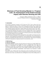
Figure 10.9 illustrates the inverted cylindrical magne-
tron (ICM) RF sputtering gun set-up [38]. This consists
of a water-cooled copper cathode which houses a cylind-
rical target material surrounded by a ring magnet con-
centric with the target. A stainless steel thermal shield is
mounted to shield the magnet from the thermal radiation
coming from the heated table. The anode is recessed in
the hollow-cathode space. It aids in collecting electrons
and negative ions minimizing ‘re-sputtering’ the growing
film. Outside the deposition chamber, a copper ground
wire is attached between the anode and the stainless steel
chamber. A DC bias voltage could be applied to the
anode to alter the plasma characteristics in the cathode/
anode space. The sputter gas enters the cathode region
through the space surrounding the table.
Using the above set-up, Cukauskas et al.[38]wereable
to deposit BST films at temperatures ranging from 550 to
800
C. The substrate temperature was maintained by two
quartz lamps, a type-K thermocouple and a temperature
controller. The films were deposited at 135 W to a film
thickness of 7000 A
.Thefilms were cooled to room
temperature in 1 atm of oxygen before removing them
from the deposition unit. This was then followed by
annealing the films in 1 atm of flowing oxygen at a
temperature of 780
C for 8 h in a tube furnace.
10.4 BULK MICROMACHINING
FOR SILICON-BASED MEMS
Starting in the early 1960s, bulk micromachining has
since matured as the principal silicon micromachining
technology. Bulk micromachining is employed to fabri-
cate the majority of commercial devices available today.
The term ‘bulk micromachining’ arises from the fact that
this type of micromachining is used to realize micro-
mechanical structures within the bulk of a single-crystal
silicon wafer by selectively removing the wafer material.
The microstructures fabricated using bulk micromachin-
ing may have thicknesses ranging from sub-microns to
the full thickness of a wafer (usually 200 to 500 mm), and
lateral dimensions ranging from microns to the full
diameter of a wafer (usually 75 to 200 mm).
For bulk-micromachined silicon microstructures, a
wafer-bonding technique is necessary for the assembled
Anode
Thermal
shield
Shutter
Table with
quartz lamps
(
T
s ≤ 850°C)
Ba
0.5
Sr
0.5
TiO
3
Magnet
Substrate
holder
Thermocouple
Cr–Al
Figure 10.9 Schematic of an ICM sputter gun [38].
268 Smart Material Systems and MEMS
MEMS devices. The bulk micromachining technique
allows us to selectively remove significant amounts of
silicon from a substrate to form membranes on one side
of a wafer, a variety of trenches, holes or other structures
(Figure 10.3). In recent years, a vertical-walled bulk
micromachining techniques known as single crystal
reactive etching and metallization (SCREAM) which is
a combination of anisotropic and isotropic plasma etch-
ing, is used [29].
The construction of any complicated mechanical device
requires not only the machining of individual components
but also the assembly of the components to form a
complete set. In micromachining, bonding techniques
are used to assemble individually micromachined parts
to form a complete structure. For example, wafer bonding,
when used in conjunction with micromachining techni-
ques, allows the fabrication of 3-dimensional structures
that are thicker than a single wafer. Several processes have
been developed for bonding silicon wafers. The most
common bonding process is fusion bonding. These tech-
niques are described in Section 10.2.5. In the following
sections, we will describe the commonly used bulk micro-
machining processes.
10.4.1 Wet etching for bulk micromachining
Wet chemical etching is widely used in semiconductor
processing. It is used for lapping and polishing to give an
optically flat and damage-free surface and to remove
contamination that results from wafer handling and
storing. Most importantly, it is used in the fabrication
of discrete devices and integrated circuits of relatively
large dimensions to delineate patterns and to open
windows in insulating materials. It is to be noted that
most of the wet etching processes are isotropic. That is,
etch rate is unaffected by crystallographic orientation.
However, some wet etchants are orientation depen-
dant, i.e. have the property of dissolving a given crystal
plane of a semiconductor much faster than other planes
(see Table 10.4). In diamond and zinc blende lattices, the
(111) plane is more closely packed than the (100) plane
and, hence, for any given etchant the etch rate is expected
to be slower.
A commonly chemical used orientation-dependent
etchant for silicon consists of a mixture of KOH in
water and isopropyl alcohol. The etch rate is about
2.1 mm/min for the (110) plane, 1.4 mm/min for the
(100) plane and only 0.003 mm/min for the (111) plane
at 80
C; therefore, the ratio of the etch rates for the (100)
and (110) planes to the (111) plane are very high, at
400:1 and 600:1, respectively.
10.4.2 Etch-stop techniques
Properties that make etchants indispensable to the micro-
machining of three-dimensional structures are their
selectivity and directionality. As etching processes in
polar solvents are fundamentally charge-transport phe-
nomena, the etch rate will depend on the type of dopant
and its concentration, and an external bias. Etch pro-
cesses can therefore be made selective by the use of
dopants – heavily doped regions etch slower or are halted
electrochemically when observing the sudden rise in
current through an etched n–p junction.
A region at which wet (or dry) etching tends to slow
down (or halt) is called an ‘etch stop’. There are several
ways in which an etch-stop region can be created. In the
following paragraphs, we discuss such methods by which
etch selectivity is achieved.
In the electrochemical etching of silicon, a voltage is
applied between the silicon wafer (anode) and a counter-
electrode (cathode) in the etching solution. The funda-
mental steps of the etching mechanism are:
(1) Injection of holes into the semiconductor to raise it to
a higher oxidation state, Si
þ
.
(2) Attachment of negatively charged hydroxyl groups
(OH
À
) to positively charged Si.
(3) Reaction of the hydrated silicon with the complexing
agent in the solution.
(4) Dissolution of the reaction products into the etchant
solution.
The conventional electrochemical etch-stop technique is
an attractive method for fabricating microsensors and
Table 10.4 Anisotropic etching characteristics of
different wet etchants for single-crystalline silicon.
Reprinted from Applied Surface Science, vol. 164,
R.K. Kupka, F. Bouamrane, C. Cremers, and
S. Megtert, Microfabrication: LIGA-X and
applications, pp. 97–110, Copyright 2000, with
permission from Elsevier
Etchant Temperature (
C) Etch rate (mm/h)
Si (100) Si (110) Si (111)
KOH:H
2
O80 841260.21
KOH 75 25–42 39–66 0.5
EDP 110 51 57 1.25
N
2
H
4
H
2
O 118 176 99 11
NH
4
OH 75 24 8 1
Silicon Fabrication Techniques for MEMS 269
micro-actuators since it has the potential for allowing
reproducible fabrication of moderately doped n-type
silicon microstructures with good thickness control.
However, a major limiting factor in the use of this
process is the effect of a reverse-bias leakage current in
the junction. Since the selectivity between n-type and
p-type silicons in this process is achieved through the
current-blocking action of the diode, any leakage in this
diode will affect the selectivity. In particular, if the
leakage current is very large, it is possible for etching
to terminate well before the junction is reached. In some
situations, the etching process may fail completely
because of this leakage. This effect is well known, and
alternative biasing schemes employing three (or four)
electrodes have been proposed to minimize this problem.
Alternately, dopant-selective techniques that use pulsed
anodizing voltages applied to silicon samples immersed
in etching solutions can be used [39].
In bias-dependent etching, oxidation is promoted by a
positive voltage applied to the silicon wafer, which causes
an accumulation of holes at the Si–solution interface.
Under these conditions, oxidation at the surface proceeds
rapidly while the oxide is readily dissolved by the solu-
tion. Holes, such as H
þ
ions, are transported to the cathode
and are released as hydrogen (gas). Excess hole–electron
pairs can, in addition, be created at the silicon surface, e.g.
by optical excitation, to increase the etch rate.
Silicon membranes are generally fabricated using the
etch-stop phenomenon of a thin, heavily boron-doped layer,
which can be epitaxially grown or formed by the diffusion
or implantation of boron into a lightly doped substrate. This
stopping effect is a general property of basic etching
solutions such as KOH, NaOH, ethylene diamine pyroca-
techol (EDP) and hydrazine (see Table 10.5). Due to the
heavy boron-doping, the lattice constant of silicon
decreases slightly. This leads to highly strained membranes
that often show slip planes.Theyare,however,tautand
fairly rugged, even at a few micron thickness and $1cm
diameter. The technique, however, is not suited to stress-
sensitive microstructures as this could lead to the movement
of structures without an external load.
The main benefits of the high-boron etch stop are the
independence of crystal orientation, the smooth surface
finish and the possibilities it offers for fabricating
released structures with an arbitrary lateral geometry
in a single etch step. On the other hand, the high levels
of boron required are known to introduce considerable
mechanical stress into the material, which may cause
buckling or even fracture in a diaphragm or other
‘double-clamped’ structures. Moreover, the introduction
of electrical components for sensing purposes into these
microstructures, such as the implantation of piezoresis-
tors, is inhibited by the excessive background doping.
The latter consideration constitutes an important limita-
tion to the applicability of the high-boron-dose etch
stop.
The pulsed potential anodization technique is used to
selectively etch n-type silicon [39]. The difference in the
dissolution time of anodic oxide formed on n-type and
p-type silicon samples under identical conditions is used
for etch selectivity. However, the difference in dissolution
time is believed to be due to a difference in oxidation rates
caused by the limited supply of holes in n-type samples
[39]. This technique is applicable in a wide range of
anodizing voltages, etchant compositions and tempera-
tures. It differs from the conventional p–n junction etch
stop in that the performance of the etch stop does not
depend on the rectifying characteristics or quality of a
diode. Using this technique, p-type microstructures of both
low and moderate doping can be fabricated. Hence, the
pulsed potential anodization technique opens up the pos-
sibility for the creation of fragile microstructures in p-type
silicon.
The main problems with the conventional electroche-
mical etch stop and the pulsed potential anodization
techniques are related to the etch holders required for
contacting the epitaxial layer (and the substrate with
several electrodes) and for protecting the ‘epitaxial-side’
of the wafer from the etchant. Any leakage in these
holders interferes with proper operation of the etch stop.
Moreover, mechanical stress introduced by the holder
reduces production yield substantially. The development
Table 10.5 Dopant-dependent etch rates of selected silicon wet etchants. W.C. Tang, ‘‘Micromechanical devices
at JPL for space exploration,’’ IEEE Aerospace Applications Conference Proceedings, vol. 1, ß 1998 IEEE
Etchant Temperature (100) Etch rate (mm/min) for (100) Etch rate (mm/min) for
(diluent) (
C) boron doping (10
19
cm
À3
boron doping $ 10
20
cm
À3
EDP (H
2
O) 115 0.75 0.015
KOH (H
2
O) 85 1.4 0.07
NaOH (H
2
O) 65 0.25–1.0 0.025–0.1
270 Smart Material Systems and MEMS
of a reliable wafer holder for anisotropic etching with an
electrochemical etch stop is not straightforward. The
process of making contact to the wafer itself can also be
critical and difficult to implement. Therefore a single-step
fabrication of released structures with either a conven-
tional electrochemical etch stop or pulsed potential ano-
dization techniques may be troublesome.
An alternative etch-stop technique which does not
require any external electrodes (or connections to be
made to the wafer) has been recently developed. This
new technique is referred to as the photovoltaic electro-
chemical etch-stop technique (PHET) [40]. The PHET
approach can be used to produce the majority of struc-
tures that can be formed by either the high-boron or the
electrochemical etch-stop process [40]. PHET does not
require the high impurity concentrations of the boron
etch stop and does not require external electrodes or an
etch holder as in the conventional electrochemical etch-
stop or pulsed anodization techniques. Free-standing
p-type structures with an arbitrary lateral geometry can
be formed in a single etch step. In principle, PHET is to
be seen as a two-electrode electrochemical etch stop
where the potential and current required for anodic
growth of a passivating oxide is not applied externally,
but is generated within the silicon itself. The potential
essentially consists of two components, being the photo-
voltage across an illuminated p–n junction and the
‘Nernst’ potential of an n-Si/metal/etchant solution elec-
trochemical cell.
The buried oxide process generates microstructures by
means of exploiting the etching characteristics of a
buried layer of silicon dioxide. After implanting oxygen
into a silicon substrate using suitable ion-implantation
techniques, high-temperature annealing causes the oxy-
gen ions to interact with the silicon to form a buried layer
of silicon dioxide. The remaining thin layer of single-
crystal silicon can still support the growth of an epitaxial
layer from a few microns to many tens of microns thick.
In micromachining, the buried silicon dioxide layer is
used as an etch stop. For example, the etch rate of an
etchant such as KOH slows down markedly as the etchant
reaches the silicon dioxide layer. However, this process
has the potential for generating patterned silicon-dioxide-
buried layers by appropriately implanting oxygen.
10.4.3 Dry etching for micromachining
As discussed above, bulk micromachining processes
using wet chemical etchants, such as EDP, KOH and
hydrazine, can yield microstructures on single-crystal
silicon (SCS) by ‘undercutting’ the silicon wafer. The
etch stop in these cases can be either crystal-orientation-
dependent or dopant-concentration-dependent. How-
ever, the type, shape and size of the SCS structures
that can be fabricated with the wet chemical etch
techniques are severely limited. On the other hand, a
dry-etch-based process sequence has been developed to
produce suspended, SCS mechanical structures and
actuators [41]. This process is known as the SCREAM
(single crystal reactive etching and metallization) pro-
cess. SCREAM uses RIE processes to fabricate released
SCS structures with lateral feature sizes down to 250 nm
and with arbitrary structure orientations on a silicon
wafer. SCREAM includes process options to make
integrated, ‘side-drive’ capacitor actuators. A compati-
ble high step-coverage metallization process using
metal sputter deposition and isotropic metal dry etch
is used to form ‘side-drive’ electrodes. The metalliza-
tion process complements the silicon RIE processes
used to form the ‘movable’ SCS structures.
The SCREAM process can be used to fabricate com-
plex circular, triangular structures in SCS, often with a
single mask. These structures can include integrated,
high-aspect-ratio and conformable capacitor actuators.
The capacitor actuators are used to generate electrostatic
forces and so produce micromechanical motion.
10.5 SILICON SURFACE MICROMACHINING
Since the beginning of the 1980s, much interest has been
directed towards micromechanical structures fabricated
by a technique called surface micromachining. The
resulting ‘2½-dimensional’ structures are mainly located
on the surface of a silicon wafer and exist as a thin film –
hence, the ‘half-dimension’. The dimensions of these
surface-micromachined structures can be an order of
magnitude smaller than bulk-micromachined structures.
The main advantage of surface-micromachined structures
is their easy integration with IC components, since the
same wafer surface can also be processed for the IC
elements.
Surface micromachining does not shape the bulk
silicon, but instead builds structures on the surface of
the silicon by depositing thin films of ‘sacrificial layers’
and ‘structural layers’ and by removing eventually the
sacrificial layers to release the mechanical structures
(Figure 10.10). The dimensions of these surface-
micromachined structures can be several orders of mag-
nitude smaller than bulk-micromachined structures. The
prime advantage of surface-micromachined structures is
their easy integration with IC components, since the
Silicon Fabrication Techniques for MEMS 271
wafer is also the ‘working’ one for the IC elements.
Surface micromachining can therefore be used to build
monolithic MEMS devices.
Surface micromachining could also be performed
using dry-etching methods. Plasma etching of the silicon
substrate with SF
6
/O
2
-based and CF
4
/H
2
-based gas mix-
tures is advantageous since high selectivities for the
photoresist, silicon dioxide and aluminum masks can
be achieved. However, when using plasma etching, a
large ‘undercut’ of the mask is observed. This is due to
the isotropic fluorine-atom-etching of silicon which is
known to be high compared with the vertical etch
induced by ion bombardment. In contrast, reactive-ion
etching of poly-Si using a chlorine/fluorine gas combina-
tion produces virtually no ‘undercut’ and almost vertical
etch profiles when using a photoresist as a masking
material. Thus, rectangular silicon patterns which are
up to 30 mm deep can be formed by using chlorine/
fluorine plasmas out of poly-Si films and silicon wafer
surfaces.
Silicon microstructures fabricated by surface micro-
machining are usually planar (or two dimensional) struc-
tures. Other techniques involving the use of thin-film
structural materials released by the removal of an under-
lying sacrificial layer have helped to extend conventional
surface micromachining into the ‘third dimension’.By
connecting polysilicon plates to the substrate and to each
other with hinges, 3-D micromechanical structures can
be assembled after release. Another approach to 3-D
structures have used the conformal deposition of poly-
silicon and sacrificial oxide films to fill deep trenches
previously etched in the silicon substrate.
Sacrificial-layer technology generally uses polycrys-
talline rather than single-crystal silicon (SCS) as the
structural material for the fabrication of microstructures.
Low-pressure chemical vapor deposition (LPCVD) of
polysilicon is well known in standard IC technologies
and has excellent mechanical properties similar to those
of SCS. When polycrystalline silicon is used as the
structural layer, sacrificial-layer technology normally
employs silicon dioxide as the sacrificial material. This
sacrificial layer is required during the fabrication process
to realize some microstructures but does not constitute
any part of the final device.
The key processing steps in sacrificial-layer technol-
ogy are:
(1) Deposition and patterning of a sacrificial silicon
dioxide layer on the substrate.
(2) Deposition and definition of a polysilicon film.
Lithography
Lithography
Mask
Mask
Sacrificial layer
(silicon dioxide)
Development of
the sacrificial layer
Removal of
the sacrificial layer
Deposition of
the structural layer
Patterning of
the structural layer
Polycrystalline
silicon
Final
structure
(1) (2)
(3) (4)
(6)(5)
Figure 10.10 Processing steps for a typical micromachining process [23]. Reproduced by permission of Gabor Kiss
272 Smart Material Systems and MEMS
(3) Removal of the sacrificial oxide by lateral etching in
hydrofluoric acid (HF), i.e. etching away of the oxide
underneath the polysilicon structure.
Here, we refer to polysilicon and silicon dioxide as the
structural and sacrificial materials, respectively. Several
other material combinations are also used in surface
micromachining.
10.5.1 Material systems in sacrificial layer
technology
An important consideration in the fabrication of an ideal
mechanical microstructure is that it is without any residual
mechanical stress, so that the films deposited have no
significant residual strain. In particular, doubly supported
free-standing structures will buckle in the presence of a
relatively modest residual compressive strain in the struc-
tural material. By choosing the appropriate deposition
conditions and by optimizing the annealing step, an almost
strain-free structural material layer can be obtained.
Surface micromachining requires a compatible set of
structural materials, sacrificial materials and chemical
etchants. The structural materials must possess the phy-
sical and chemical properties that are suitable for the
desired application. In addition, the structural materials
must have appropriate mechanical properties, such as
high yield and fracture strengths, minimal creep and
fatigue and good wear resistance. The sacrificial materi-
als should also be able to avoid device failure during the
fabrication process. Furthermore, they should have good
adhesion and a low residual stress in order to eliminate
device failure by delamination and/or cracking. The
etchants must have excellent etch selectivity and they
must be able to etch-off the sacrificial materials without
affecting the structural ones. In addition, the etchants
must also have appropriate viscosity and surface tension
characteristics.
The common IC-compatible materials used in surface
micromachining are as follows. (1) Poly-Si/silicon diox-
ide – LPCVD-deposited poly-Si as the structural material
and LPCVD-deposited oxide as the sacrificial material.
The oxide is readily dissolved in HF solution without the
poly-Si being affected. Together with this material sys-
tem, silicon nitride is often used for electrical insulation.
(2) Polyimide/aluminum – in this case, polyimide is the
structural material and aluminum is the sacrificial mate-
rial. Acid-based etchants are used to dissolve the alumi-
num sacrificial layer. (3) Silicon nitride/poly-Si – silicon
nitride is used as the structural material, whereas poly-Si
is the sacrificial material. For this material system,
silicon anisotropic etchants, such as KOH and EDP, are
used to dissolve the poly-Si. (4) Tungsten/silicon dioxide
– CVD-deposited tungsten is used as the structural
material with oxide as the sacrificial material. HF solu-
tion is used to remove the sacrificial oxide. Other IC-
compatible materials, such as silicon carbide, ‘diamond-
like’ carbon, zinc oxide and gold, are also used.
10.5.1.1 Polycrystalline silicon/silicon dioxide
The poly-silicon/silicon dioxide material system is the
most common one used in the silicon-surface micro-
machining of MEMS. This uses poly-silicon deposited
by LPCVD as the structural material and a thermally
grown (or LPCVD) oxide as the sacrificial material. The
oxide is readily dissolved in HF solution, without
affecting the poly-silicon. Silicon nitride is often used,
together with this material system for electrical insula-
tion. The advantages of this material system include the
following:
(1) Both poly-silicon and silicon dioxide are used in IC
processing and, therefore, their deposition technolo-
gies are readily available.
(2) Poly-silicon has excellent mechanical properties and
can be doped for various electrical applications. Dop-
ing not only modifies the electrical properties but can
also modify the mechanical properties of poly-silicon.
For example, the maximum ‘mechanically-sound’
length of a free-standing beam is significantly larger
for a phosphorous-doped compared with undoped
poly-silicon. However, in most cases the maximum
length attainable is limited by the tendency of the
beam to stick to the substrate.
(3) The oxide can be thermally grown and deposited by
CVD over a wide range of temperatures (from about
200 to 1200
C) which is very useful for various
processing requirements. However, the quality of
oxide will vary with the deposition temperature.
(4) The material system is compatible with IC processing.
Both poly-silicon and silicon dioxide are standard
materials for IC devices. This commonality makes
them highly desirable in sacrificial-layer-technology
applications which demand integrated electronics.
10.5.1.2 Polyimide/aluminum
In this second material system, the polymer ‘polyimide’
is used for the structural material while aluminum is used
for the sacrificial material. Acid-based aluminum etch-
ants are used to dissolve the aluminum sacrificial layer.
Silicon Fabrication Techniques for MEMS 273
The three main advantages of this material system are:
(1) Polyimide has a small elastic modulus which is $ 50
times smaller than that of polycrystalline silicon.
(2) Polyimide can take large strains before fracture.
(3) Both polyimide and aluminum can be prepared at
relatively low temperatures (< 400
C).
(4) However, the main disadvantage of this material system
lies with polyimide in that it has unfavorable viscoe-
lastic characteristics (i.e. it tends to creep) and so such
devices may exhibit considerable parametric drift.
10.5.1.3 Other material systems
In the third material system of silicon nitride/poly-Si,
silicon nitride is used as the structural material and
poly-Si as the sacrificial material. For this material
system, silicon anisotropic etchants such as KOH and
EDP are used to dissolve the poly-Si.
In the fourth material system of tungsten/oxide, tung-
sten deposited by CVD is used as the structural material
with the oxide as the sacrificial material. Here again, an
HF solution is used to remove the sacrificial oxide.
Similarly, silicon nitride is employed as the structural
material with aluminum as the sacrificial layer instead of
poly-Si.
10.6 PROCESSING BY BOTH BULK
AND SURFACE MICROMACHINING
Many MEMS devices are fabricated by either bulk
micromachining or surface micromachining, as described
in the previous sections. Their relative merits and demer-
its are compared in Table 10.6. It is possible to combine
advantages of both of these approaches by following a
‘mixed route’ for fabricating MEMS. The process flow
for a ‘microgripper’ fabricated with this mixed approach
is shown in Figure 10.11. In the first step, with thermally
grown silicon dioxide as a mask, boron is diffused into
the wafer at 1125
C. The masking SiO
2
and borosilicate
glass (BSG) grown during this diffusion are removed.
Then, a 2 mm thick layer of phosphosilicate glass (PSG)
and a 2.5 mm thick polysilicon layer are deposited by
LPCVD. This polysilicon layer is patterned by RIE in a
CCl
4
plasma. Polysilicon at the back side of the wafer is
later removed. Then, the PSG film is deposited in three
steps to reach a thickness of 6 mm. This is used for
diffusing phosphorous into the polysilicon layer (by
annealing at 1000
C) and to protect it while bulk micro-
machining. The alignment window in Figure 10.11(c) is
used for ‘front-to-back’ reference. Break lines are pat-
terned on the PSG around the polysilicon gripper area to
prevent cracks. The PSG film on the back side is also
patterned. Unwanted silicon from the back side is removed
by etching in EDP (bulk micromachining). On the front
side, the EDP causes undercut etching of channels beneath
the PSG break line, eventually connecting to the open
space caused from the back side etch. The PSG film
(sacrificial layer) is then removed from both the top and
bottom. Thus, the structure on the top side of the wafer is
thought of as being fabricated by surface micromachining.
10.7 LIGA PROCESS
Even though miniaturization is immensely increased by
silicon surface micromachining, the small sizes/masses
created are often insufficient for viable sensors and,
particularly, actuators. The problem is most acute in
Table 10.6 Comparison of bulk-and surface-micromachining processes for MEMS fabrication.
Aspect Bulk Surface
micromachining micromachining
Maturity Well established Relatively new
Ruggedness Yes – structures can withstand vibration Less rugged
and shock
Die area Large mass/area Small mass/area (reduced
(suitable for accelero meters,increases cost) sensitivity, reduces cost)
IC Not fully integrated IC compatible
compatibility
Structural Limited Wide range
geometry possible
Materials Well characterized Relatively new
274 Smart Material Systems and MEMS
capacitive mechanical microsensors and especially capa-
citively driven micro-actuators because of the low cou-
pling capacitances. Deep etching techniques, such as
LIGA, have been developed in order to address this
problem but are difficult to realize for silicon.
‘LIGA’ is a German acronym for Lithographie,
Galvanoformung, Abformung (lithography, galvanoform-
ing, molding). This versatile technique was developed by
the Research Center in Karlsruhe in Germany in the early
1980s using X-ray lithography for mask exposure, galva-
noforming to form the metallic parts and molding to
produce micro-parts with plastics, metals, ceramics, or
their combinations [42,43]. A schematic diagram of the
LIGA process flow is shown in Figure 10.12. The X-ray
LIGA relies on synchrotron radiation to obtain necessary
X-ray fluxes and uses X-ray proximity printing. Inherent
advantages are its extreme precision, depth of field and
very low intrinsic surface roughness [44]. With the LIGA
process, the microstructure heights can be up to hundreds
of microns to several millimeters, while the lateral resolution
is kept at the submicron level due to the advanced X-ray
lithography. Various materials can be incorporated into the
LIGA process, allowing electrical, magnetic, piezoelec-
tric, optical and insulating properties of sensors and
actuators with a high-aspect ratio, which are not possible
to make with the silicon-based processes. In addition, by
combining the sacrificial layer technique and the LIGA
process, advanced MEMS with moveable microstructures
p
+
support cantilever
Si wafer
Si die
Si die
PSG
PSG
V-
g
roove
V-groove
Poly
Etch channel
Open
space
Alignment
window
Si wafer
Poly
PSG
PSG break line
Alignment
window
Poly
PSG
Si wafer
PSG
p
+
Si wafer
PSG
Poly
p
+
Si wafer
p
+
(a)
(b)
(c)
(d)
(e)
Figure 10.11 Process flow for MEMS ‘microgripper’ fabricated with bulk and surface micromachining. C J. Kim, A.P. Pisano, and
R.S. Muller, Silicon-Processed overhanging microgripper, J. Microelectromechanical Systems, Vil. 1, # 1992 IEEE
Silicon Fabrication Techniques for MEMS 275
can be built (Figure 10.13). However, the high production
cost of the LIGA process, due to the fact that it is not easy
to access the X-ray source, limits the application of LIGA.
Another disadvantage of the LIGA process relies on the
fact that structures fabricated using LIGA are not truly
three-dimensional, because the third dimension is always
in a ‘straight’ feature. The quality of fabricated structures
often depends on secondary effects during exposure and
effects like resist adhesion. A similar technique, UV-LIGA,
relying on thick UV resists, is a useful fabrication process,
but with less precision. Modulating the spectral properties
of synchrotron radiation, 3-D components with different
size regimes can be fabricated using X-ray lithography [44].
Considerations for these cases are shown in Table 10.7.
Figure 10.12 Schematic of the LIGA process [23]. Reproduced by permission of Gabor Kiss
276 Smart Material Systems and MEMS
Figure 10.13 Combination of LIGA process and sacrificial layer process [45]. A. Rogner, et al., ‘‘LIGA based flexible
microstructures for fiber chip coupling,’’ J. Micromech. Microeng., vol. 1, 1991, # IOP
Table 10.7 X-ray lithography for various feature sizes [44]. Reprinted from Applied Surface Science, vol. 164,
R.K. Kupta, F. Bouamrane, C. Cremers, and S. Megtert, Microfabrication: LIGA-X and applications, pp. 97–110,
Copyright 2000, with permission from Elsevier
Feature Low-aspect-ratio High-aspect-ratio High-aspect-ratio High-aspect-ratio
nanostructures nanostructures microstructures ‘cm structures’
Photon energy range 500 eV–2 keV 2–5 keV 4–15 keV > 15 keV
Exposable resist < 5 mm < 50 mm < 1mm < 2cm
(PMMA) thickness
Membrane SiC, 2 mm; diamond, Be, 50 mm; Be, 300 mm; Be, 500 mm;
thickness 5 mm Be, 20 mm D263, 5 mm D263, 15 mm D263, 50 mm
Absorber (Au, W) 100–500 nm 500nm to 10–20 mm20–50 mm
thickness 10 mm
Proximity contrast <10 dB 10–15 dB 15–20 dB >20 dB
Development time s–min min–hh–days days
Application Rapid mass production 2-D photonic Micromechanics, —
of nanostructures crystals micro-optics
Silicon Fabrication Techniques for MEMS 277
LIGA-based fabrication procedures of various systems
for micromechanics (such as micromotors, microsensors,
spinnerets, etc.) and micro-optics, micro-hydrodynamics,
microbiology, medicine, biology and chemistry (micro-
chemical reactors) are under various stages of develop-
ment. A comparison of LIGA with the bulk and surface
micromachining technologies used in MEMS is given in
Table 10.8 [46].
REFERENCES
1. H. Fujita, ‘Future of actuators and microsystems’, Sensors
and Actuators, A56, 105–111 (1996).
2. H. Fujita, ‘Microactuators and micromachines’, Proceedings
of the IEEE, 86, 1721–1732 (1998).
3. G.T.A. Kovacs, N.I. Maluf and K.E. Petersen, ‘Bulk micro-
machining of silicon’, Proceedings of the IEEE, 86, 1536–
1551 (1998).
4. J.M. Bustillo, R.T. Howe and R.S. Muller, ‘Surface micro-
machining for microelectromechanical systems’, Proceed-
ings of the IEEE, 86, 1552–1574 (1998).
5. H. Guckel, ‘High-aspect-ratio micromachining via deep
X-ray lithography’, Proceedings of the IEEE, 86, 1586–
1593 (1998).
6. Y. Xia and G.M. Whitesides, ‘Soft lithography’, Angewandte
Chemie, International Edition, 37, 550–575 (1998).
7. V.K. Varadan and V.V. Varadan, ‘Three dimensional poly-
meric and ceramic MEMS and their applications’, Proceed-
ings of SPIE, 2722, 156–164 (1996).
8. K. Ikuta and K. Hirowatari, ‘Real three dimensional micro-
fabrication using stereo lithography and metal molding’,in
Proceedings of IEEE MEMS’93, IEEE, Piscataway, NJ,
USA, pp. 42–47, (1993).
9. T. Katagi and N. Nakajima, ‘Photoforming applied to fine
machining’,inProceedings of IEEE MEMS’93, IEEE,
Piscataway, NJ, USA, pp. 173–178, (1993).
10. C.S. Taylor, P. Cherkas, H. Hampton, J.J. Frantzen,
B.O. Shah, W.B. Tiffany, L. Nanis, P. Booker, A. Salahieh
and R. Hansen, ‘A spatial forming – a three dimensional
printing process’,inProceedings of IEEE MEMS’94, IEEE,
Piscataway, NJ, USA, pp. 203–208 (1994).
11. G. Thornell and S. Johansson, ‘Microprocessing at the
fingertips’, Journal of Micromechanical and Microengineer-
ing, 8, 251–262 (1998).
12. S. Middelhoek and S.A. Audet, Silicon Sensors, Academic
Press, London, UK (1989).
13. K.E. Peterson, ‘Silicon as a mechanical material’, Proceed-
ings of the IEEE, 70, 420–457 (1982).
14. J. Bryzek, K. Peterson and W. McCulley, ‘Micromachines on
the march’, IEEE Spectrum, 31(5), 20–31 (May 1994).
15. L S. Fan, Y C Tai and R.S. Muller,‘Integrated movable
micromechanical structures for sensors and actuators’,
IEEE Transactions: Electron Devices, 35, 724–730
(1988).
16. V.K. Varadan, X. Jiang and V.V Varadan, Microstereolitho-
graphy and other Fabrication Techniques for 3D MEMS,
John Wiley & Sons, Ltd, London, UK (2001).
17. C. Vieu, F. Carcenac, A. Pe
´
pin, Y. Chen, M. Mejias,
A. Lebib, L. Manin-Ferlazzo, L. Couraud and H. Launois,
‘Electron beam lithography: resolution limits and applica-
tions’, Applied Surface Science, 164, 111–117 (2000).
18. S. Gwo, ‘Scanning probe oxidation of Si
3
N
4
masks for
nanoscale lithography, micromachining and selective epi-
taxial growth on silicon’, Journal of Physics and Chemistry
of Solids, 62, 1673–1687 (2001).
19. S.M. Sze, Physics of Semiconductor Devices, John Wiley
& Sons, Inc., New York, NJ, USA (1981).
20. H. Seidel, ‘The mechanism of anisotropic silicon etching and
its relevance for micromachining’,inProceedings of the
International Conference on Solid-State Sensors and Actua-
tors, Institute of Electrical Engineers of Japan Tokyo, Japan,
pp. 120–125 (1987).
21. K.W. Shaw, Z.L. Zhang and N.C. MacDonald, ‘ SCREAM: a
single mask, single-crystal silicon, reactive ion etching
Table 10.8 Various technologies used in MEMS fabrication [46]. W.C. Tang, ‘‘Micromechanical devices at JPL for
space exploration,’’ IEEE Aerospace Applications Conference Proceedings, vol. 1, ß 1998 IEEE
Feature Bulk (100) wafer Surface LIGA
Maximum structure thickness Wafer thickness < 50 mm < 500 mm
Planar geometry Rectangular Unrestricted Unrestricted
Minimum planar feature size 1.4 Âdepth 1 mm3mm
Side-wall features 54.74
slope Limited by 0.2 mm runout
dry etch over 400 mm
Surface and edge definitions Excellent Mostly adequate Very good
Material properties Very well controlled Mostly adequate Well controlled
Integration with electronics Demonstrated Demonstrated Difficult
Capital investments and cost Low Medium High
278 Smart Material Systems and MEMS
process for microelectromechanical structures’, Sensors and
Actuators, A40,63–70 (1994).
22. G.T.A. Kovacs, N.I. Maluf and K.E. Petersen, ‘Bulk micro-
machining of silicon’, Proceedings of the IEEE, 86, 1536–
1551 (1998).
23. G. Stix, ‘Trends in micromechanics: micron machinations’,
Scientific American,72–80 (November 1992).
24. M. Madou, Fundamentals of Microfabrication, CRC Press,
Boca Raton, FL, USA (1997).
25. J.B. Lasky, ‘Wafer bonding for silicon-on-insulator technol-
ogies’, Applied Physics Letters, 48,78–80, (1986).
26. H. Ohashi, J. Ohura, T. Tsukakoshi and M. Simbo,
‘Improved dielectrically isolated device integration by
silicon-wafer direct bonding (SDB) technique’,inInterna-
tional Electron Devices Meeting Technical Digest IEEE,
New York, NY, USA, pp. 210–213 (1986).
27. U. Apel, H.G. Graf, C. Harendt, B. Hofflinger and T. Ifstrom,
‘A 100-V lateral DMOS transistor with a 0.3 micron channel
in a 1 micron silicon-film-on-insulator-on silicon’, IEEE
Transactions: Electron Devices, 38, 1655–1659 (1991).
28. C. Harendt, H.G. Graf, B. Hollinger and E. Penteker,
‘Silicon direct bonding for sensor applications – character-
ization of the bond quality’, Sensors and Actuators, A25,
87–92 (1991).
29. W.H. Ko, J.T. Suminto and G.J. Yeh, ‘Bonding techniques
for microsensors’, Studies in Electrical and Electronic
Engineering 20,41–61 (1985).
30. J.W. Gardner, V.K. Varadan and O. Awadelkarim, Micro-
sensors, MEMS and Smart Devices, John Wiley & Sons, Ltd,
London, UK (2001).
31. M. Ohring, The Materials Science of Thin Films, Academic
Press, San Diego, CA, USA (1991).
32. H.O. Pierson, Handbook of Chemical Vapor Deposition
(CVD): Principles, Technology and Applications, 2nd
Edn, Noyles Publications, New York, NY, USA (1999).
33. M. Jennifer and M.G. Allen, ‘Wireless micromachined
ceramic pressure sensors’,inProceedings of the IEEE
MEMS’ 99, IEEE, Piscataway, NJ, USA, pp. 511–516
(1999).
34. L.C. Chin, V.V. Varadan and V.K. Varadan, ‘Hybrid finite
element formulation for periodic piezoelectric arrays sub-
jected to fluid loading’, International Journal of Numerical
Methods in Engineering, 37, 2987–3003 (1994).
35. J.H. Won, H. Paek, Y.S Huang, K.K. Kim and Y.S. Cho,
‘Phase formation and characteristics of RF sputtering of
barium strontium titanate thin films on various bottom
layers’, Journal of Materials Science Materials in Electro-
nics, 6, 161–164 (1995).
36. X.X. Xi, H C. Li, W.Si, A.A. Sirenko, I.A. Akimou, J.R.
Fox, A.M. Clark and J. Hao, ‘Oxide thin films for Tunable
microwave devices’, Journal of Electroceramics, 4, 393–405
(2000).
37. I. Levin, R.D. Leapman and D.L. Kaiser, ‘Microstructure
and chemistry of nonstoichiometric (Ba,Sr)TiO
3
thin films
deposited by metalorganic chemical vapor deposition’,
Journal of Materials Research, 15, 1433–1436 (2000).
38. E.J. Cukauskas, S.W. Kirchoefer and J.M. Pond, ‘ Low-loss
Ba
0.5
Sr
0.5
TiO
3
thin films by inverted magnetron sputtering,
Journal of Applied Physics, 88, 2830–2835 (2000).
39. S.S. Wang, V.M. McNeil and M.A. Schmidt, ‘An etch-stop
utilizing selective etching of n-type silicon by pulsed
potential anodization’, Journal of Microelectromechanical
Systtems, 1, 187–192, (1992).
40. E. Peeters, D. Lapadatu, R. Puers and W. Sansen, ‘PHET, an
electrodeless photovoltaic electrochemical etch-stop techni-
que’, Journal of Microelectromechamical Systems, 3, 113–
123 (1994).
41. Z.L. Zhang and N.C. McDonald, ‘An RIE process for
submicron, silicon electromechanical structures’, Journal
Micromechamical and Microengineering, 2,31–38 (1992).
42. H. Guckel, ‘High-aspect-ratio micromachining via deep
X-ray lithography’, Proceedings of the IEEE, 86, 1586–
1593 (1998).
43. J. Mohr, P. Bley, C. Burabaum, W. Menz and U. Wallarabe,
‘Fabrication of microsensor and microactuator elements by
the LIGA process’,inTransdycers’91, Proceedings of the
International Conference in Solid-State Sensors and Actua-
tors, IEEE Electron Devices Society, IEEE, New York, NY,
USA, pp. 607–609 (1991).
44. R.K. Kupka, F. Bouamrane, C. Cremers and S. Megtert,
‘Microfabrication: LIGA-X and applications’, Applied Sur-
face Science, 164,97–110 (2000).
45. A. Rogner, W. Ehrfeld, D. Manchmeger, P. Bley, C.
Burbaum and J. Mohr, ‘LIGA based flexible microstructures
for fiber chip coupling’, Journal of Micromechamical and
Microengineering, 1, 167–170, (1991).
46. W.C. Tang, ‘Micromechanical devices at JPL for space
exploration’,inIEEE Aerospace Applications Conference
Proceedings, Vol. 1, IEEE, Piscataway, NJ, USA, pp. 461–
470 (1998).
Silicon Fabrication Techniques for MEMS 279
11
Polymeric MEMS Fabrication Techniques
11.1 INTRODUCTION
The advancement of silicon-based micro electromecha-
nical systems (MEMS) closely follows developments in
silicon semiconductor processing technology. Various
processing approaches have already been established for
the integration of silicon-based MEMS with standard
CMOS processing. For precision devices, and for devices
requiring integrated electronics, silicon is presently unri-
valed. However, it is not necessarily the best material
for all applications. For example, silicon is brittle, it is
only available in specific shapes (wafers), it is limited to
2-D or very limited 3-D structures, it is incompatible
with many chemical and biological substances and fab-
rication requires sophisticated, expensive equipment
operated in a clean-room environment. These often
limit the low-cost potential of silicon-based MEMS.
Polymer-based MEMS are gaining momentum rapidly
due to their potential for conformability and other special
characteristics not available with silicon. In general,
polymer-based devices may not be as small or as com-
plex as those with silicon. However, polymers are flex-
ible, chemically and biologically compatible, available in
many varieties and can be fabricated in truly 3-D shapes.
Most of these materials and their fabrication methods are
inexpensive.
Polymer MEMS are particularly advantageous in mod-
erate-performance devices which are low cost or dispo-
sable. Many silicon devices are packaged inside
polymers. On the other hand, polymer MEMS can be
‘self-packaged’. Active polymer components can take
advantage of several functional polymers to increase
their functionality. MEMS can definitely benefit from
the fairly large polymer industry. While conventional
integrated circuits cannot be made in polymers, electro-
nic circuits based on organic thin-film transistors (TFTs)
are feasible. The technology of organic TFTs is nearing
its maturity, and is finding several applications in systems
requiring large coverage area, structural flexibility and
low cost. These noticeable advantages are also common
for polymer MEMS. Although the existing technology of
organic TFTs cannot rival the well-established silicon
semiconductor technology, especially in terms of speed,
they are still useful in displays, several high-volume,
low-performance, disposable devices and sensors.
Polymers are very large molecules (macromolecules)
made up of a number of small molecules. The small
molecules that connect with each other to build up the
polymer are referred to as monomers, and the reaction by
which they connect together is called polymerization.
Two types of polymers are employed for micromachining
polymeric MEMS devices – structural polymers and
sacrificial polymers. The structural polymer is usually a
UV-curable polymer with urethane acrylate, epoxy acry-
late or acryloxysilane as the main ingredient. Its low
viscosity allows easy processing through automatic
equipment or manual methods without the addition of
solvents or heat to reduce the viscosity. It also complies
with all VOC regulations. It has excellent flexibility and
resistance to fungus, solvents, water and other chemicals.
Other physical, chemical, mechanical and thermal prop-
erties are given in Table 11.1 [1]. This structural polymer
may be used as a backbone structure for building the
multifunctional polymer described below.
For 3-D MEMS devices, the polymers need to have
conductive and possibly piezoelectric or ferroelectric
properties. In addition, for these polymers to be used
for polymeric MEMS, they should have strong interfacial
adhesion between the functional polymer and conducting
polymer layers, elastic moduli to support the deformation
initiated by MEMS devices, excellent overall dimen-
sional stability (allowing local mobility) and long-term
Smart Material Systems and MEMS: Design and Development Methodologies V. K. Varadan, K. J. Vinoy and S. Gopalakrishnan
# 2006 John Wiley & Sons, Ltd. ISBN: 0-470-09361-7
environmental stability. In addition, their processes
should help attachment of nanoceramics and/or conduc-
tive phases and formation of a uniform coating layer.
Furthermore, many of these polymers provide a large
strain under an electric field and thus can be used
as actuators for MEMS-based devices such as micro
pumps.
The polymer processing techniques include photopoly-
merization, electrochemical polymerization and vacuum
polymerization, either stimulated by electron bombard-
ment or initiated by ultraviolet irradiation or microwave-
assisted polymerization. These methods are also widely
used for processing and curing thin and thick polymer
films on silicon-based electronic components.
Several polymeric materials useful in MEMS have
already been discussed in Chapter 2. It has been men-
tioned that UV-radiation curing has significant advan-
tages in the context of fabricating MEMS devices. In this
chapter, we discuss the technologies involved in such
fabrication.
Stereolithography has evolved as a viable technique
for rapid prototyping used in several industries. Micro-
stereolithography is a natural extension of this for fabri-
cating objects at a smaller scale. Another common
technique for fabricating three-dimensional polymer
structures is by molding. Microstereolithography and
micromolding can be extended to fabricate ceramic and
metallic structures by starting with a mixture of their
powders in a suitable polymer matrix. Special techniques
such as electroplating can also be used to fabricate 3-D
metallic structures. Fabrication techniques for 3-D struc-
tures with both polymers and metals are discussed next.
The last section in this chapter addresses combined
architectures where silicon-based and polymer-based
techniques are combined for increased flexibility.
11.2 MICROSTEREOLITHOGRAPHY
Several new manufacturing technologies that build
devices ‘layer-by-layer’ have emerged recently. Using
these technologies, the time for fabricating these devices
of virtually any complexity has become short, measur-
able in hours rather than in days, weeks or months. These
rapid prototyping (RP) technologies consist of various
manufacturing processes by which a solid physical model
of a device is fabricated directly from its 3-D CAD
model, without the need for any special tooling. This
CAD model is generated by 3-D CAD software pro-
grams, scan or model data created by 3-D digitizing
systems. An important difference between RP and tradi-
tional micromachining techniques is that here devices are
built by adding a material (e.g. ‘layer-by-layer’) instead
of removing it.
11.2.1 Overview of stereolithography
Stereolithography (SL) is the best known rapid prototyping
system. SL was introduced in the early 1980s by teams
around the world [2–4], as a three-dimensional manufac-
turing process based on photopolymerization, where a laser
beam is directed onto the surface of a optically curable
liquid plastic (resin) to produce solid objects. The stereo-
lithography process begins with the generation of a three-
dimensional CAD model of the desired object, followed by
slicing this model into a series of closely spaced horizontal
planes representing the two-dimensional cross-sections of
the 3-D object, each at a slightly different z-coordinate. All
of these 2-D models are next translated into numerical
Table 11.1 General properties of polymers used
in MEMS.
Physical properties
Adhesion (#600 ‘Cellotape’) Excellent
Clarity Transparent
Flammability, ASTM D635 Self-extinguishing
Flexibility Good
Weather resistance Excellent
Chemical properties
Fungus resistance, ASTM G21 Excellent
Resistance to chemicals Excellent
Resistance to solvents Excellent
Resistance to water Excellent
Thermal properties
Continuous operating range (
C) 65–125
Decomposition temperature (
C) 242
Mechanical properties
Tensile strength (psi), 3454
ASTM D 683
Percentage elongation, 5.2
ASTM D 683
Dielectric properties
Dielectric permittivity 1.9–2.0
(200–1000 MHz)
Loss tangent 0.023–0.05
(200–1000 MHz)
282 Smart Material Systems and MEMS
control codes and merged together into a final ‘build file’ to
control the laser beam scanning and z-axis movement. The
desired object is then built from a UV-curable resin in a
layer-by-layer additive fashion (Figure 11.1).
SL is a photopolymerization process, linking small
molecules (monomers) into larger molecules (polymer).
Most SL systems utilize the principle of UV-radiation
curing of polymers. Different photopolymers based on
free-radical photopolymerization and cationic photo-
polymerization are normally used in SL prototyping. In
general, photopolymerization is a process initiated by the
photons generated by UV light leading to either breaking
of the monomer double bonds or ring opening (so-called
‘reactive species’), resulting in chain propagation and the
cross-linked polymer chain is finally formed when the
chain propagation is terminated.
The generalized molecular structures of three major
photopolymer systems, namely monofunctional acrylate,
epoxy and vinyl ether, are shown in Figure 11.2. The
selection of the photopolymer for a particular SL fabrica-
tion process depends on the requirements for dimensional
accuracy and mechanical properties of each individual
photopolymer formulation.
Three-dimensional modeling for the prototypes is done
with CAD software on a PC or workstation. The design
model and the support data are converted to a STL format
through a specific interface [5]. STL files comprise a
mesh of connected triangles, representing the 3-D object.
These triangle categories determine how the vectors are
generated to represent the surfaces to build the part.
Vectors are very small lines which are traced by the
laser to fabricate polymer objects [6].
After necessary corrections to the model, the designed
object is then sliced into a number of layers consisting of
cross-sections of a 3-D object (slice files or SLI files).
The slicing layer thickness may be selected from con-
sideration of the ‘stair-casing’ effect. When these trian-
gles are sliced, three types of vectors are created to define
the surface boundaries and internal structure on a layer-
by-layer basis – layer borders, cross-hatches and skin fill.
The cross-hatch vectors in the internal grid structures are
created to strengthen the walls and maintain structure
integrity. The skin-filling vectors, usually a series of
closely located parallel vectors, define the horizontal
surfaces.
All slice files (support and object files) are then
merged to generate SLA format data in the form of
four files (layer, vector, range and parameter files). The
layer file defines the types of vector blocks in each layer.
The vector file contains vector data used to build each
layer and the range file contains user-specified ranges and
parameters for fabrication. The parameter file has the
control for global part building. The numerical control
(NC) codes for controlling the light scanning and eleva-
tor movement are included in these files. Parameters,
such as laser intensity and scanning speed, should also be
selected before executing these NC codes.
SL systems have components with CAD design and
layer preparation functions and a laser scanning or imaging
system. A typical SL system is shown schematically in
Figure 11.3. The imaging system for SL includes a light
source (laser or lamp) and beam delivery and focusing
elements (Figure 11.3). The laser or lamps must be appro-
priate for the resin used. Wavelength, output beam shape
and available power are important characteristics. Helium–
cadmium (He–Cd) and argon lasers are preferred in
most SL systems due to the availability of appropriate
wavelengths. The key advantages of He–Cd lasers are
UV light
Mirror
Elevator
Vat of photo
curable
solution
Figure 11.1 Principle of Stereolithography.
CC
C
O
O
O
R
R
H
CC
H
H
H
H
H
CC
O
R
H
H
H
Acrylate
Epoxy
Vinyl ether
Figure 11.2 General structures of monofunctional acrylate,
epoxy, and vinylether monomers [5].
Polymeric MEMS Fabrication Techniques 283
low power consumption, long lifetime and low instal-
lation and operation costs. One disadvantage of this is
the low output power. At present, He–Cd lasers with
output powers of 50 to 100 mW are available at 325 nm.
In contrast, argon lasers with high UV output powers
(over 1 W) at 351 and 364 nm are available. However,
disadvantages of argon-laser-based SL systems include
higher power consumption, shorter lifetimes and higher
installation and operating costs.
Beam-delivery elements are used to limit the laser beam
path, to keep the overall size compact and to provide an
appropriately sized laser spot on the surface of the resin. A
typical SL system may employ two orthogonally mounted,
servo-controlled, galvanometer-driven mirrors to direct the
laser beams onto the surface of the vat. A focused beam
with a small-beam-spot size is obtained when the beam
passes through a focusing objective and shoots onto the
resin surface. An optical shutter is usually used to control
the beam ‘on/off’ which functions according to the build
files. Mechanical shutters requiring about 1 ms to change
the state have been replaced with an acoustic optical
modulator with a typical response time of 1 ms, allowing
faster and more precise fabrication.
11.2.2 Introduction to microstereolithography
Microstereolithography (MSL) is a method derived from
conventional stereolithography and works on similar
principles, but in much smaller dimensions. MSL (also
called ‘micro-photoforming’) was introduced in 1993
to fabricate high-aspect-ratio and complex 3-D micro-
structures [7,8]. In contrast to conventional subtractive
micromachining, microstereolithography is an additive
process, which enables fabrication of high-aspect-ratio
microstructures with novel smart materials. MSL is com-
patible in principle with silicon processes and batch
fabrication [9,10].
In MSL, a UV laser beam is focused to a spot size of
about 1 to 2 mm to solidify a thin layer of about 1 to
10 mm thickness. Submicron resolution of the x–y–z
translation stages and a very fine UV beam spot enable
precise fabrication of complex 3-D microstructures using
MSL. Unlike SL, MSL usually does not need supports
during the fabrication because the solidified polymer is
strong enough to support its own weight and the float-
ation force can support free-standing polymer micro-
structures [7]. Monomers used in MSL and SL are both
UV-curable systems, but their viscosity requirements are
different. In MSL, the viscosity of the monomers should
be kept low to ensure a good layer recoating since surface
tension may prevent efficient filling of the liquid and
the formation of a flat surface on the micro-scale. The
viscosity of the monomer systems used in SL [11] varies
from 170 cps to 3800 cps, while in MSL the viscosity of
the monomer is two orders of magnitude lower (e.g. 6
cps for HDDA) [7]. Another difference is that some
of the monomer systems used for most projection-type
MSL are visible-light curable.
Laser
source
Program on
Computer
Beamforming
optics
Photopolymer
resin
Galvanometric
x-y scanner
Substrate
Leveling &
Elevator
System
Figure 11.3 Block schematic of a typical stereolithography system [5].
284 Smart Material Systems and MEMS
An MSL system operates with the same working
procedure as an SL system. A 3-D solid model designed
with CAD software is sliced into a series of 2-D layers
with uniform thickness. The NC codes generated for each
sliced 2-D file is then executed to control the UV beam
scanning. The focused scanning UV beam is absorbed
by an UV-curable solution consisting of monomer and
photoinitiators, leading to the polymerization. As a result,
a polymer layer is formed according to each sliced 2-D
layer. After one layer is solidified, the elevator moves
downward and a new layer of liquid resin can be solidi-
fied. With the synchronized beam scanning and the z-axis
motion, complicated 3-D micro-parts are built in a layer-
by-layer fashion.
Various MSL systems aimed at improving the precision
and speed of fabrication have been developed. Scanning
MSL [7–9,11,12] and projection MSL [10,13–15] are the
two major approaches. Scanning MSL builds the solid
micro-objects in a spot-by-spot and line-by line fashion,
while projection MSL builds one layer with one exposure,
significantly saving the time of fabrication.
11.2.3 MSL by scanning methods
Most of the MSL systems developed thus far are based
on a scanning method which is similar to the widely used
conventional stereolithography. A 3-D microstructure
can be fabricated with the scanning method in which a
well-focused laser beam (with spot size of $1 mm) is
directed onto the resin surface to initiate the polymeriza-
tion, scanning either the light beam or the work piece and
by repeating the layer preparation. This scanning method
is also called vector-by-vector MSL [16].
Although the classical MSL system has a focusing
problem which prevents high-resolution fabrications,
its fast fabrication speed is a definite advantage due to
its implication in industrial mass production. One of the
limitations of conventional MSL is that commercially
available galvanometric mirrors are not suitable for high-
resolution MSL because of de-focusing and the resulting
poor scanning resolution (hundreds of microns). A series
of integrated hardened (IH) polymer stereolithography
processes have been developed to overcome this limitation
[7,17]. These IH processes are based on the scanning
method.
The schematic for an MSL system with the IH process
is shown in Figure 11.4, where the light source used is
UV lamp (xenon lamp) and the beam is focused on the
resin surface through a glass window. The focus point of
the apparatus remains fixed during the fabrication and
the workpiece in a container attached to an x–y stage is
moved, in order to emulate the scanning done by the
galvanometric mirrors in the conventional system. Using
an x–y stage to move the workpiece leads to a smaller
focus spot, indicating a higher fabrication resolution. In
addition, there is no need of a dynamic focus lens as the
focal point is fixed. The glass window was attached to the
z-stage for precise control of the layer thickness.
Typical specifications of the IH process are listed
below:
Spot size of UV beam, 5 mm.
Position accuracy, 0.25 mm (in the x–y direction) and
1.0 mminthez-direction.
Minimum unit size of hardened polymer, 5 mm Â
5 mm Â3 mm (in the x, y, and z directions).
Maximum size of fabricated structure, 10 mm Â
10 mm Â10 mm.
Features of the IH process include a capability for
building real 3-D and high-aspect-ratio microstructures,
processibility of various materials, a ‘mask-less’ and cost-
effective process, a medium range of accuracy (3–5 mm)
and the possibility of ‘desktop’ micro-fabrication. It should
be pointed out that the fabrication speed is relatively lower
than that of classical MSL, because the scanning speed
of the x–y stage with the container is lower than that of
galvanometric scanning.
To overcome the limitation of fabrication speed of the
basic IH process, a mass-producible IH process, called
the Mass-IH process, was proposed by Ikuta et al. in
microcomputer
UV source
z
-stage
x
-
y
stage
shutter
Figure 11.4 Schematic of a system for the IH process [7].
K. Ikuta, and K. Hirowatari, Real three dimensional microfab-
rication using stereo lithography and metal molding, Proc. IEEE
MEMS’ 93, ß 1993 IEEE
Polymeric MEMS Fabrication Techniques 285
1996 to demonstrate the possibility of mass production of
3-D microstructures by MSL [10]. The Mass-IH process
uses optical fibers for multi-beam scanning. An array
composed of numerous single-mode optical fibers is used
here to enable high-speed production of multiple struc-
tures. Other specifications of the system remain the same
as those of the original IH process. Although the fabrica-
tion speed can be improved significantly, this Mass-IH
process needs further improvements in its resolution and
capability for integration of more fibers.
Both the IH and Mass-IH processes are based on a
scanning method with layer-by-layer fabrication, sharing
the same principles of conventional SL. Problems caused
by this fabrication approach include limitation of the
depth resolution by thickness of the stacked-up layer and
the micro-scale deformation and destruction of the soli-
dified microstructures due to the viscous nature of the
liquid monomer. The surface tension of the liquid mono-
mer decreases the precision of the 3-D fabrication [18].
The Super IH process can be used to solidify the
monomer at a specific point in the 3-D space by focusing
a laser beam into the liquid monomer. Thus, 3-D struc-
tures are fabricated by scanning the focused spot in three
dimensions inside the liquid, enabling 3-D fabrication
without any supports or sacrificial layers. Since there is
no layer preparation step in the super IH process, the
influence of viscosity and surface tension is minimal. A
schematic diagram of the super IH process is shown in
Figure 11.5, which consists of an He–Cd laser (442 nm),
optical shutter, galvano-scanner set, x–y–z stages, objec-
tive lens, etc. The laser beam was focused inside the
monomer volume and by co-ordinating the beam scan-
ning and z-stage movement, any 3-D structures can be
formed inside the liquid. The properties of a UV-curable
monomer system must be precisely tuned to ensure that
the polymerization happens only in the focus point,
similar to two-photon MSL [11]. A typical UV monomer
system used in this case is a mixture of urethane acrylate
oligomer, monomer and photoinitiator [18].
Although the resolution of the super IH process is less
than 1 mm and the fabrication speed can be increased by
combining the galvano-scanning mirror and x–y stage,
the optics system used in this case is more expensive than
the other two types of IH processes. This process also
requires the development of specific monomer systems.
A limitation of most scanning MSL processes is the
minimum thickness of the resin layer during the layer
preparation due to the viscosity and surface tension of the
liquid monomer. The two-photon MSL process over-
comes this problem since the resin does not have to be
layered. Usually, only one photon is absorbed during the
photochemical change. However, recently a large number
of experiments in which multiple photons are absorbed
for the photochemical change in a single particle have
been observed. Multi-photon excitation is a non-linear
process, observed only at high intensities [19].
Two-photon absorption is one of the most popular
methods of multiple-photon excitation for photochemical
change. There are two kinds of mechanisms for two-
photon excitation. The first is called sequential excita-
tion, which involves a real intermediate state of the
absorbing species. This intermediate state becomes
very populated by the first photon, and can act as the
starting point for the absorption of the second one. The
real intermediate state A
*
has a well-defined lifetime,
typically 10
À4
to 10
À9
s. This means that the second
photon must be absorbed by the same particle within the
lifetime of A
*
to cause the photochemical change. Since
in sequential excitation the particle is best excited by a
resonantly absorbed photon, the overall sequential process
is also referred to as resonant two-photon excitation.
A set-up for the two-photon MSL is shown in Figure 11.6.
The beam from a mode-locked titanium sapphire laser
is directed to the galvanic-scanning mirrors and is
focused with an objective lens into the resin. The monitor-
ing system including a camera is used to ensure focusing
and to monitor fabrication. A z-stage moves along the
optical axis for multilayer fabrication. The longest total
Galvano scanner
x
–
y
–
z
-stage
Lens
UV polymer
He–Cd laser
Shutter
ND filter
Computer
Figure 11.5 Schematic of the super IH process [18]. K. Ikuta,
S. Maruo, and S. Kojima, New micro stereo lithography for
freely moved 3D micro structure- super IH process with sub-
micron resolution, Proc. IEEE MEMS’ 98, ß 1998 IEEE
286 Smart Material Systems and MEMS
length of a structure in the direction of the optical axis
is a limitation of two-photon MSL although this has a very
good depth resolution. In addition, the system is more
expensive than most of the other MSL systems.
Another widely used MSL apparatus for 3-D micro-
fabrications is based on a free-surface method that
utilizes x–y stage scanning (Figure 11.7) [9,12]. In this
method, all of the optics for the beam delivery remain
fixed, but an x–y stage moves simultaneously the resin
tank and the vertical axis onto which the plate supporting
the fabrications was attached. The scanning method is
similar to the one used in the IH process, but the galvano-
scanning is replaced with an x–y stage scanning so that
system is simplified and the focus precision is enhanced.
In this MSL process, a free-surface method was adopted
for layer preparation, rather than the constrained surface
(with a window) method used in the IH process. This
overcomes the disadvantage of the latter, where micro-
structures may be destroyed because of the parts sticking
to the window, by utilizing free-surface layer preparation.
With the free-surface method, the time needed to obtain a
fresh layer of resin on top of a cured layer depends on the
rheological properties of the resin, and so a resin with a
low viscosity is preferred. Free-surface MSL is a single-
photon-based photopolymerization process, and hence
the curing volume is relatively large. However, by adding
a light-absorbing medium into the resin, the line width
and depth can be decreased as required [9,12]. If the
beam delivery system is optimized to obtain the finest
beam spot size, the line width of 1–2 mm and a depth of
10 mm can be obtained with free-surface MSL [12].
The advantages of free-surface MSL include a simple
set-up, good focusing and high resolution. However, the
workpiece scanning has a limitation in the scanning speed
due to the fact that relative movement between the work-
piece and the liquid resin may cause a waved surface on
the fabricated micro-objects. In addition, precision stages
are required for this MSL because any stage motion errors
will be reflected directly in the fabricated parts.
11.2.4 Projection-type methods of MSL
As seen from the previous section, although the scanning
MSL can be used for the fabrication of very fine, high-
aspect-ratio, 3-D microstructures, the fabrication speed
for mass production of components is low. The scanning
MSL builds objects in a layer-by-layer fashion, but each
layer is built in a line-by-line way. The projection MSL is
proposed for building 3-D microstructures more rapidly,
although still in a layer-by-layer way. However, in this
case each layer is built by just one exposure through a
mask, thus significantly saving time. Two types of
projection MSL are introduced here: one is with real
mask to generate pattern projection for exposure curing
[14] and the other is with dynamic-mask projection
(LCD projection method) [13].
In real-mask-projection lithography, similar to photo-
lithography, an image is transferred to the liquid
Monitor
CCD camera
Objective lens
x
-scan mirror
y
-scan mirror
z
-scan stage
Lamp
Focused beam
Photopolymerizable resin
Shutter
Attenuator
Ti:sapphire laser
Argonionlaser
Figure 11.6 Schematic of 3-D micro-fabrication with two-
photon absorption [20]. S. Maruo, and S. Kawata, Two-photon-
absorbed near-infrared photopolymerization for threedimen-
sional microfabrication, J. of Microelectromechanical Systems,
Vol. 7, No. 4, ß 1998 IEEE
Micro
computer
AOM
UV laser
Mirror
Converging
lenses
x
-
y
-
z
stage
Figure 11.7 Schematic of free-surface microstereolithography
[12]. Microsystem Technologies, 2–2, 1996, pp. 97–102, Stereo-
lithography and microtechnologies, S. Zissi, A. Bertsch, J.Y.
Jezequel, S. Corbel, J.C. Andre, and D.J. Lougnot, with kind
permission of Springer Science and Business Media
Polymeric MEMS Fabrication Techniques 287
photopolymer by irradiating a UV beam through a
patterned mask (as shown in Figure 11.8) and another
fresh layer of liquid photopolymer is then prepared on
top of the patterned solid polymer. By repeating the
above mask-based exposure and layer preparation, mul-
tilayer 3-D microstructures will be finally built by the
described mask-projection MSL [14,17,21].
Similar to scanning MSL, the fabrication precision in
this case can be related to the exposure. The curing depth
strongly depends on the laser exposure and the distance
between the mask and the resin surface. The lateral
dimension is marginally influenced by the exposure but
is determined mainly by the mask pattern if the distance
between mask and resin surface is fixed. A large distance
between the mask and resin surface results in relatively
large lateral dimensions due to diffraction of the beam
[14]. Therefore, in high-precision mask-projection MSL,
the mask should be located close to the resin surface to
reduce light diffraction. This real-mask-projection MSL
can produce high-aspect-ratio micro-fabrications with a
few different cross-sections at a high fabrication preci-
sion. However, for truly 3-D micro-fabrications, a num-
ber of masks are needed, making it not only time-
consuming but also expensive.
Dynamic-mask-projection MSL utilizes a dynamic-mask
generator instead of the real mask and allows the fabrica-
tion of a complete layer by just one exposure. This leads
to quick fabrication of complex 3-D micro objects. A
schematic of a dynamic-mask-projection MSL is shown in
Figure 11.9 [13]. For the exposure of a complete layer, the
irradiation beam is shaped with a computer-controlled liquid
crystal display (LCD) used as a dynamic-mask generator.
In general, an addressed LCD light valve array (or
panel) acting as a projector is used to control light ‘on/
off’. The liquid crystal effect is adopted to modulate the
light transparency of the panel. By the liquid crystal
effect the electrical and optical characteristics of the
liquid crystal materials are changed upon application of
an electric field. The nematic phase is one of the most
important materials for light valves applications. It con-
sists of rod-like molecules, more or less parallel to each
other. The vector that defines the orientation of the long
axes of these molecules is called the ‘director’. The
optical properties of nematic liquid crystals can be varied
by manipulation of the orientation of the director in a
device by an electric field. The LCD panel is made of
pixels physically separated by a thread of electrical con-
nections being used for control. Every pixel is a small cell
which contains matter in its liquid crystal state, and can
be set either to its transparent or to its opaque state by
changing the orientation of the molecules it is made of.
The pixels in their opaque state stop the light, in contrast
to those in their transparent state. Usually, the LCD panel
is addressed by a thin-film-transistor (TFT) array.
For using an LCD in projection MSL, a CAD file with
white and black coloring is translated into a numerical
control code which is sent to the LCD device via a
computer; the LCD can then function as a dynamic
mask with controlled imaging. When a beam passes
through this LCD, it carries the pattern of the layer. The
light beam is focused on the resin surface, allowing
selective polymerization of the exposed areas corre-
sponding to the transparent pixels on the LCD. The
remaining principles of operation, such as layer pre-
paration, beam on/off control, etc., are similar to the
standard MSL. It may be noticed that the z-stage is the
only movable element in the system.
The dynamic-projection MSL fabrication process has
a reasonably good accuracy. Even though dynamic-
projection MSL has disadvantages, such as low lateral
resolution and small scope of fabrication (currently
only several millimeters), this MSL process has great
UV light
source
Photomask
Lens
Resin
z- stage
Figure 11.8 Microstereolithography using real-mask projec-
tion [14].
Light
source
Shutter
Pattern
generator
Mirror
Shutter controller
PC main control
CAD image
z-translation stage
Figure 11.9 Schematic of dynamic-mask-projection microster-
eolithogrphy [13]. Microsystem Technologies, 1997, pp. 42–47,
Microstereolithography using a liquid crystal display as dynamic
mask-generator, A. Bertsch, S. Zissi, J.Y. Jezequel, S. Corbel,
and J.C. Andre, Fig 4, with kind permission of Springer Science
and Business Media
288 Smart Material Systems and MEMS
potential due to its capability for batch fabrication of 3-D
microstructures.
11.3 MICROMOLDING OF POLYMERIC
3-D STRUCTURES
Although a number of micro-fabrication techniques,
including silicon micromachining, LIGA and microster-
eolithography, have been developed for MEMS, many of
them are faced with problems of low speed of fabrication
and/or high cost of production [22]. In this context,
micromolding technology assumes significance in
MEMS fabrication because of its capability of large
volume capacity. The micromolding techniques useful
for MEMS include injection molding [23], hot emboss-
ing [24], jet molding [25], replica molding [26], micro-
transfer molding [27], micromolding in capillaries [28]
and solvent-assisted micromolding [29] (Table 11.2).
In principle, the first three processes can be used for
fabrication of micro-parts with high-aspect-ratios and
even 3-D features and the last four are especially useful
for thin microstructures.
The key aspects in micromolding include degassing
prior to molding, thermal or photochemical curing and
‘demolding’ [23]. Vacuum molding and hot isostatic
pressing have been demonstrated as helpful to exempt
gas [30]. In order to remove the polymer mold, selective
plasma etching is preferred to using the burnout process, to
prevent ‘topple’ in fine structures with high-aspect-ratios
[30,31]. The micromolding techniques are fairly well
established for plastics and ceramics.
‘Master molds’ are often built using polymers, metals or
silicon. ‘Polymer masters’ can be built using photolitho-
graphy, stereolithography, etc. ‘Metal masters’ are formed
mostly by micro-electroplating, LIGA and the DEEMO
process utilizing metallic molds [32,33]. ‘Silicon masters’
are fabricated using wet or dry etching [24,33].
The polymer mold inserts should withstand a certain
level of mechanical strength and thermal resistance since
pressure and heating are necessary during molding.
Materials used for such mold inserts range from common
photoresists to UV-curable resins used in microstereo-
lithography. To fabricate elastomer mold inserts, the
photoresist is first patterned using photolithography, the
elastomer solution (PDMS and solvent) is then poured
into the pattern followed by solvent evaporation and
curing. The PDMS mold insert is then obtained by
dissolving the photoresist pattern (Figure 11.10).
Most micromold inserts used for micromolding are
made of metals. These are widely used for plastic, metal
and ceramic micro-moldings. The fabrication approaches
include precision mechanical machining (e.g. micro
electro-discharge machining (EDM)) and lithography
Table 11.2 A brief comparison of micromolding techniques.
Molding Molding Feature Mold insert Notes Reference
type material size material
Injection Plastic Hundreds of Nickel LIGA [32]
molding microns high
Embossing Polymer $100 mm Nickel DEEMO [33]
Photoreaction; Polymer $mm Brass Faster curing than [23]
injection (photocuring) thermal reaction
molding molding
Jet molding PZT $40 mm thick — Slow process. [25]
Embossing Plastic $21 mm thick, Silicon Limited 3-D [24]
30 mm wide
Pyrolysis Ceramic Aspect ratio Polymer Good filling, degassing, [34]
molding of 5 but too high
shrinkage ($60 %)
Microtransfer Polymer Several mm Polymer Small thin structure, [27]
molding limited 3-D
Injection Plastics, Aspect ratio Polymer A broad variety of [35]
molding ceramics, of 20 materials can be
metals molded
Polymeric MEMS Fabrication Techniques 289
(e.g. E-beam, UV, X-ray) or excimer laser ablation or
microstereolithography followed by electroplating [22].
Through-mask electroplating has been used exten-
sively in the fabrication of metal mold inserts. Nickel
is the most commonly used material for the fabrication of
such inserts because of its well-known electroplating
potential, the high replication accuracy and low internal
stresses. However, the hardness of nickel is relatively low
compared with iron or stainless steel, resulting in a
limited lifetime for nickel mold inserts. Other materials
such as nickel–iron or tungsten–cobalt alloys with
enhanced hardness are also considered [22].
Laser micromachining is also used for the fabrication
of metal mold inserts [36]. As shown in Figure 11.11, a
polymer (e.g. PMMA) is machined by an excimer laser
beam. The polymer structure is then coated with a thin
evaporated metal layer which serves as the ‘seed’ layer
for the following electroplating. After electroplating, the
polymer is removed and the metal mold insert is ready
for molding. Features of mold inserts fabricated by laser
micromachining include the possibility of a large variety
of 3-D shapes, a lateral resolution of the order of microns
and the feasibility for ‘hundreds-of-micron-high’ struc-
tures. This is a mask-less process.
Mechanical machining processes such as micromill-
ing, sawing, grinding and micro-EDM are suitable for the
fabrication of metal micromold inserts. Several materials
are available for such precision machining processes.
Since the fabrication of metal mold inserts by precision
mechanical machining results in large structures, lithogra-
phy can be used for micro-scale mold insert fabrication
[22]. However, lithography-based mold insert fabrications
have limited applications due to abrasion and wear of
nickel, slow speed of electroplating and the possibility of
voids in the electroplated mold insert structures.
Silicon micromold inserts are useful for micromolding
with flat and even surfaces [37]. Both silicon wet and dry
etching can be used for their fabrication. For example, a
silicon mold insert with a lateral dimension of 5 mmand
an aspect ratio of 2 has been fabricated by RIE etching
[37]. Although silicon mold inserts have limited shaping
variations, a high resolution of mold insert is possible
by the approach. Silicon mold inserts are useful for hot
embossing of polymer structures and isotropic pressing
casting of ceramic microstructures [24,31].
11.3.1 Micro-injection molding
Injection molding is a widely used technique for shaping
plastics, metals, metal alloys and ceramics. However,
several modifications should be made in the conventional
injection molding technique to facilitate micro-scale
injection molding. There are many air-vent slots in
conventional injection molding to facilitate the escape
of air during molding. Since the dimensions of these vents
are generally close to the size of the microstructures,
similarly sized unwanted structures will be formed if
they are used in micro-injection molding. To avoid this,
the air inside the mold is removed before molding, and
hence air-vent slots are not necessary in micro-injection
molding. In addition, a temperature-variation program
must be included in micro-injection molding because of
the high aspect ratio of the microstructures. The tempera-
tures of the mold inserts should be kept higher and for
longer durations, to ensure good mold filling. Further-
more, since the microstructures are relatively weak at high
temperatures, it is necessary to cool the mold down to a
stable temperature at which the molded part has sufficient
mechanical strength and stable chemical properties.
Therefore, in addition to the heating used in conventional
injection molding, an inside heating and cooling technique
(called the variotherm process) should be used in micro-
injection molding [35].
Photoresist coating
Lithography
Pattern transfer
Mold insert
Photoresist
Elastomer
Figure 11.10 Elastomer mold inserts fabrication.
Laser ablation
Metal evaporation coating
and Electroplating
Polymer removal
Polymer removal
Figure 11.11 Metal mold insert fabrication using laser ablation
and electroplating [36].
290 Smart Material Systems and MEMS
A typical micro-injection molding process has the
following steps:
Placing mold insert into the molding chamber.
Evacuation of the chamber.
Heating the plastic pellets to above the melting point.
Injection of polymer at controlled pressure and tem-
perature.
Cooling.
De-molding.
The molding temperature is set above the melting point
of the polymer being used. The pressure applied ranges
from 500 to 2000 bars. Typically, injection-molded micro-
parts have a minimum wall thickness of 20 mmandan
aspect ratio of more than 20. However, structural details
below 0.2 mm have been achieved. The thermoplastics used
in micro-injection molding include polysulfonate (PSU),
polycarbonate (PC), polyoxymethylene (POM), polyamide
(PA) and poly(ether ether ketone) (PEEK) [35,39].
11.3.2 Micro-photomolding
Micro-photomolding is a process based on micro-injection
molding that uses a photocuring technique to solidify
the feedstock system instead of the heating/cooling-
based phase change in micro-injection molding. The
feedstock system is a reactive polymer resin with a low
viscosity (e.g. methyl methacrylates, unsaturated poly-
esters). The steps involved in the micro-photomolding
process are [23]:
Sealing the molding chamber and its evacuation.
Injection of the liquid resin (injection pressure < 20 bar).
Curing using intense UV/visible radiation under con-
stant holding pressure to compensate curing shrinkage.
Removal of the molded micro-component from the
molding tool.
The curing time of the micro-photomolding process
depends on the photochemical properties of the resin,
mold thickness and radiation intensity. Usually, a few
minutes are needed to complete photomolding. The
photomolding of powders is made possible by the addi-
tion of ceramic or metal powders into the resin [23].
11.3.3 Micro hot-embossing
Hot embossing is a process for the replication of plastics
by heating and pressing the polymer thick films to fit into
the mold insert, as shown in Figure 11.12. Hot embossing
differs from injection molding in the fact that the heating
temperature is just above the glass transition temperature
in hot embossing, while the temperature should be above
the melting point used in injection molding. Another
difference is that polymer films are used as the starting
materials in this case, compared to the pellets of poly-
mers used in injection molding.
The embossing tool and the polymer film substrate are
mounted in the hot embossing machine and are heated
separately to a temperature just above the glass transition
temperature of the polymer material. For most thermo-
plastic materials, the glass transition temperature is in
the range 120–180
C. The tool is then driven into the
substrate under a controlled force, which is kept up for
several seconds. The tool–substrate–sandwich is then
cooled below the glass transition temperature of the
polymer material. After the polymer material solidifies,
the tool is taken out of the structure. Advantages of this
method are its flexibility and the low internal stresses
and high structural replication accuracy due to the small
thermal cycle (ca. 40
C), which facilitate structural
replications in the nm-range [37].
11.3.4 Micro transfer-molding
Micro transfer-molding (mTM) was developed to fabri-
cate 3-D polymer and ceramic microstructures with sub-
micron-and nanometer-scale features. A schematic diagram
of micro transfer-molding is shown in Figure 11.13. As
a mold insert, an elastomeric tool must be fabricated first.
Unlike injection molding and hot embossing where
the hardness of the mold inserts should be high, a soft
Polymer film
Mold insert
Heating and pressing
De-molding
Figure 11.12 Hot embossing for polymer micro-component
fabrication.
Polymeric MEMS Fabrication Techniques 291
elastomeric material should be used to fabricate the mold
inserts for mTM. Usually, polydimethylsiloxane (PDMS) is
used for elastomeric tool fabrication. The Micro contact-
printing process or RIE etching may be used for fabricat-
ing the PDMS molding tool [27]. The thickness of this
tool is controlled to be less than 2 mm to ensure its
flexibility.
A drop of liquid precursor is placed on the patterned
surface of the PDMS tool and the excess liquid is
removed by a piece of flat PDMS, followed by blowing
away any drops of liquid left on the raised areas of the
mold. The filled PDMS tool is then placed onto a
substrate where the polymer structure will be built. The
prepolymer is next fully cured thermally or photochemi-
cally and the PDMS tool is finally peeled away and the
polymer microstructure is left on the substrate.
Multilayer microstructures can be fabricated with this
technique. Another characteristic of mTM is that polymer
microstructures can be formed on non-planar surfaces
[27]. One of the limitations of using mTM is that there is a
thin (< 0.1 mm) film formed between the polymeric
features due to the polymer transfer of prepolymer
from the raised surfaces of the mold and capillary
‘wicking’ of prepolymer from the PDMS relief tool.
11.3.5 Micromolding in Capillaries (MIMIC)
The micromolding in capillaries process is used to
fabricate polymeric microstructures by generating a net-
work of capillaries formed by contacting an elastomeric
master with a surface embossed with an appropriate
relief structure, and by allowing the liquid precursor to
fill the channels by capillary action [26,28]. Figure 11.14
shows the procedure of an MIMIC process. Similar to
micro transfer-molding, an elastomer (PDMS) tool is
fabricated first and is patterned with a relief structure
on its surface. It is then placed on the surface of a
substrate to form a network of channels between them.
When a drop of precursor solution is then placed at one
end of these channels, it fills the channels by capillary
action. After the solvent is evaporated and the PDMS
tool is carefully removed, the polymer microstructures
are left on the surface of the substrate. Although the
capillary action takes a long time (hours) to fill the
channels with solution, especially for small-diameter
channels (microns) and highly viscous precursor
(b)(a)
Repeat
(1) Fully cure prepolymer
(2) Flip upside down
(3) Peel PDMS away
Piace a substrate
upside down on a
filed mold
Use a block of PDMS
toscrape off the excess
prepolymer
PDMS
PDMS
PDMS
PDMS
Liquid
prepolymer
Place the filled
PDMS mold on a
substrate
Substrate
(1) Cure prepolymer
(2) Peel PDMS away
Figure 11.13 Schematic diagram of micro-transfer molding:
(a) Process flow for a single layer; (b) multiple layer structure
fabrication [27]. Reproduced with permisison of John Wiley &
Sons, Ltd.
Place PDMS mold on support
PDMS mold
Place a drop of polymer
solution at one end
Fill channels by
capillary action
Evaporate solvent and
remove PDMS mold
Figure 11.14 Schematic of micromolding in capillaries [40].
Reproduced with permisison of John Wiley & Sons, Ltd.
292 Smart Material Systems and MEMS
solutions, the MIMIC process has advantages such as
high fabrication resolution and processibility of a vari-
ety of precursor materials.
Care should be taken in choosing the solvent, as this
should not swell the PDMS mold. MIMIC is usually used
for micro-fabrications of structures ranging from 350 nm
to 50 mm size, with low processing temperatures and no
pressure applied. This method is compatible with the
semiconductor micromachining process.
11.4 INCORPORATION OF METALS AND
CERAMICS BY POLYMERIC PROCESSES
The fabrication of several advanced MEMS for
special applications often requires the integration of poly-
mers, ceramics, metals and metal alloys to utilize their
unique properties. These functional and structural ceramic
materials possess unique properties, such as high tempera-
ture/chemical resistance, low thermal conductivity, ferroe-
lectricity and piezoelectricity. The use of ceramic
materials in MEMS has attracted a great deal of attention
recently [41–45]. The three-dimensional (3-D) ceramic
microstructures are of special interest in applications such
as microengines [42] and microfluidics [43]. Various novel
approaches for ceramic micro- fabrication have been
developed. In this section, some fundamental processes
are introduced to show how these can be incorporated into
the fabrication cycle, starting with some of the processes
described thus far for polymeric materials.
11.4.1 Burnout and sintering
In 3-D ceramic and metallic micro-fabrications, poly-
mers are usually used as binders to bond solid particles to
form the desired shape. Since in most of the cases, pure
metal or ceramic structures are required, the binder is
removed (debinding) and the structures are sintered for
densification. Since binders are used in most ceramic and
metallic 3-D micro-fabrications, an understanding of the
burnout and sintering process is necessary for obtaining
highly dense ceramic and metal parts. In addition, electro-
chemical deposition is one of the most frequently used
processes for 3-D micro-fabrications. Some of the recently
developed 3-D micro-fabrication processes for ceramics,
metals and polymer/metals will also be introduced.
Debinding techniques can be done by either a solvent or
a thermal process. Since in most of the photoforming
processes the polymer is cross-linked, solvent cannot be
used to dissolve the binders and hence thermal degradation
is preferred. Therefore, the debinding process is often
called the burnout process. Thermal degradation involves
several basic steps [46]. During the early stages of heating,
thermal expansion of the liquid binder induces an hydrau-
lic pressure in the fully saturated part. As the temperature
rises, binder removal, due to evaporation from the surface,
increases. When the saturation level of the binder is
sufficiently reduced, the liquid remaining in the mix is
driven to the surface by capillary pressure, where it
evaporates. As binder removal by liquid transfer con-
tinues, gas pockets begin to coalesce, forming a network
of interconnected pores. Finally, this internal structure
creates passages for gas to flow through, allowing diffu-
sion to play an important role in debinding.
Once the overall debinding time is determined, the
heating rate and peak temperature must be carefully
selected. The heating rate is directly related to the
retaining shape. Since rapid heating often leads to cracks
and distortion, slow heating is necessary at the beginning
of the degradation. In some cases, the debinding, however,
cannot be processed in air, to avoid oxidation, e.g.
debinding of metallic structures. A controlled atmosphere
should be provided for the debinding. Hydrogen, argon or
nitrogen is often used in these cases.
Sintering is the term used to describe the consolidation
of the product by firing. Consolidation requires that
within the components, particles have to be joined
together into an aggregate for better strength. Geometric
shrinkage and densification usually occurs during sinter-
ing. Sintering densification occurs close to the melting
temperature of the material. The bonds between particles
grow by the motion of individual atoms, which is related
to the temperature. This relationship between atomic
motion and temperature varies for different materials
with different melting temperatures. For example, steel
is often sintered near 1250
C, alumina near 1600
C,
copper near 1045
C and PZT near 1200
C. Measures of
sintering include shrinkage and final sintering density.
Successful sintering leads to a density &
g
close to the
material density. Theoretically, a final sintering density
level can be 95–100 %. [47].
Recently, microwave sintering has been used for bulk
ceramics [48,49]. The obvious advantage of microwave
sintering is the possibility of quick heating, but its non-
uniformity is a concern. However, for micro-scale sinter-
ing, microwave sintering may be a good choice since the
heating uniformity will be fairly good.
11.4.2 Jet molding
Jet molding is a process developed for microfabrication
of metal and ceramic microstructures. Mixture of gas and
Polymeric MEMS Fabrication Techniques 293