Understanding And Applying Machine Vision Part 2 ppt
Bạn đang xem bản rút gọn của tài liệu. Xem và tải ngay bản đầy đủ của tài liệu tại đây (641.33 KB, 25 trang )
The vast majority of machine vision vendors are players in niche applications in specific manufacturing industries.
While generic machine vision platforms have been applied in many industries, no single company has emerged within
the machine vision industry as a dominant player with a product(s) that has been applied across a significant number of
manufacturing industries.
Several companies offer general-purpose vision platforms that have sufficient functionality permitting them to be
configured for a variety of applications. Some of these same companies are suppliers of products that address a specific
set of applications such as optical character recognition (OCR) and optical character verification (OCV). Some
companies are suppliers of image processing board sets that also offer the functionality of a vision platform and can be
utilized to address many applications like the general-purpose vision platforms.
Page 29
Figure 3.5
Turnkey system from Perceptron performing 3D dimensional analysis
on "body-in-white" in automotive assembly plant for critical dimensions,
gap andflushness.
The vast majority of the suppliers that make up the machine vision industry are suppliers of industry-specific niche
application products. There is often as much value associated with peripheral equipment necessary to provide a turnkey
solution, as there is value of the machine vision content in the system.
It is becoming increasingly more difficult to classify companies in the machine vision market. Suppliers of general-
purpose systems are extending their lines to include products that might have earlier been classified as application-
specific machine vision systems. Similarly, suppliers of image processing boards are offering boards with software that
makes their products appear to be a general-purpose machine vision system. There are a couple of board suppliers that
today actually offer turnkey, application-specific machine vision systems. There are several suppliers of application-
specific machine vision systems with turnkey systems that address specific applications in different markets (e.g.,
unpatterned and patterned/print web inspection (Figure 3.6), or 3D systems for semiconductor and electronic
applications).
Page 30
Figure 3.6
Pharma Vision system from Focus Automation inspecting a roll
of pharmaceutical labels on a rewinder for print defects.
3.5—
Machine Vision Industry-Related Definitions
The following are definitions associated with the different segments of the machine vision industry:
Merchant machine vision vendor - A company that either offers a general-purpose, configurable machine vision
system or a turnkey application-specific machine vision system. In either case, without the proprietary machine vision
functionality, there would be no purchase by a customer. The proprietary machine
Page 31
vision hardware could be based either on commercially available image board level products or proprietary vision
computer products.
Image processing board set suppliers (IPBS) - A company offering one or more products, such as a frame grabber,
that often incorporates an A/D, frame storage, and output look-up tables to display memorized or processed images.
These boards can operate with either digital or analog cameras. In some cases, they merely condition the image data
out of a camera making it compatible with processing by a personal computer.
Often these boards will be more "intelligent," incorporating firmware that performs certain image-processing
algorithmic primitives at real time rates, and off-loading the computer requirements to the firmware from the computer
itself. The interface supplied generally requires a familiarity with image processing and analysis, since one will
generally start at the algorithm level to develop an application. IPBS can be sold to GPMV builders, ASMV, builders,
merchant system integrators, OEMs, or end-users.
General-purpose machine vision system vendor (GPMV) - A company offering products that can be configured or
adapted to many different applications. The vision hardware design can be either based on commercially available
image board level products or proprietary vision computer products. The graphic user interface is such that little or no
reference is made to image processing and analysis. Rather, the interface refers to generic machine vision applications
(flaw inspection, gaging, assembly verification, find/locate, OCR, OCV, etc.) and walks the user through an
application set-up via menus or icons.
These systems may or may not have the ability to get into refining specific algorithms for the more sophisticated user.
GPMV systems are sold to application-specific machine vision system builders, merchant system integrators, OEMs,
or end-users.
A GPMV supplier can use some combination of:
Proprietary software
Proprietary flame grabber + proprietary software
Commercial frame grabber + proprietary software
Proprietary IPBS + proprietary software
Commercial IPBS + proprietary software
Proprietary hardware + proprietary software.
Application-specific machine vision vendor (ASMV) - A company supplying a turnkey system that addresses a
single specific application that one can find widely throughout industry or within an industry. Interface refers
specifically to the application itself, not to generic machine vision applications or imaging functions. In other words,
machine vision technology is virtually transparent to the user.
Page 32
The vision hardware can be either based on commercially available image board level products, general-purpose
machine vision systems, or proprietary vision computer products. ASMV systems are typically sold directly to end-
users.
An ASMV supplier can use some combination of:
Proprietary frame grabber + proprietary software
Commercial frame grabber + proprietary software
Proprietary IPBS + proprietary software
Commercial IPBS + proprietary software
Proprietary hardware + proprietary software
Commercial GPMV + proprietary software.
Machine vision software supplier (MVSW) - A company supplying software that adapts image processing and
analysis hardware to generic machine vision applications (flaw inspection, gauging, locate/find, OCR, OCV, etc.).
Usually the software is designed to adapt a commercially available image processing board for use in machine vision
applications. Alternatively, it may adapt a personal computer to a machine vision application. MVSW can be sold to
GPMV builders, ASMV, builders, merchant system integrators, OEMs, or end-users.
Web scanner supplier - A company providing a turnkey system to inspect unpatterned products produced in webs
(paper, steel, plastic, textile, etc.). These systems can capture image data using area cameras, linear array cameras, or
laser scanners. The vision hardware used in the system can be based on commercially available image board level
products, general-purpose machine vision systems or proprietary vision computers. Web scanners are typically sold to
end-users.
3D-machine vision or laser triangulation supplier - A company providing a system that offers 3D measurements
based on the calculation of range using triangulation measurement techniques. The system can use any number of
detection schemes (lateral effect photodiode, quadrant photodetector, matrix array camera, linear array camera) to
achieve the measurement. The lighting could be a point source, line source, or specific pattern.
The simpler versions collect data one point at a time. Some use a flying spot scanner approach to reduce the amount of
motion required to make measurements over a large area. Others use camera arrangements to collect both 2D and 3D
data simultaneously. Laser triangulation-based machine vision systems can be sold to GPMV builders, ASMV,
builders, merchant system integrators, OEMs, or end users.
Merchant system integrator - A company providing a machine vision system with integration services and adapting
the vision system to a specific customer's requirements. A system integrator is project-oriented. Merchant system
integrators typically sell to an end user.
A merchant system integrator provides:
Page 33
1. Turnkey system based on:
Commercial frame grabber + proprietary software or commercial software
Commercial IPBS + proprietary software of commercial software
Commercial GPMV + proprietary software or commercial software
2. Plus value added: application engineering, GUI, material handling, etc.
Captive system integrator - A company purchasing a machine vision product for its own use and employing its own
people to provide the integration services. The machine vision product will typically be either a general-purpose
machine vision system or an image board set.
Original equipment manufacturer (OEM) - A company offering a product with a machine vision value adder as an
option. An OEM includes machine vision in its product, but without machine vision, the system would still have
functionality for a customer.
Absent from this list of supplier types "value adder remarketer (VAR)." This term is so general that it loses its
meaning. Virtually every other type of company associated with applying machine vision is essentially a value adder.
In other words, a company that manufactures application-specific machine vision systems based on a commercial
general-purpose machine vision product or image processing board set is a value adder to those products.
An OEM is a company adding a whole lot of value - generally the functionality required by the user of its piece of
equipment. A merchant system integrator adds value to either a general-purpose machine vision system or image
processing boards — the value being project-specific software and hardware application engineering.
The distinctions between an ASMV, OEM, and merchant system integrator are:
ASMV - turnkey system provider; functionality purchased includes entire system; any single element of system has no
value to customer alone; sells many of the same system
OEM - machine vision is an optional value adder to existing functionality
Merchant system integrator - project-based business.
3.6—
Summary
This discussion is meant to clarify the vendor community for the prospective buyer of a machine vision system. It is
important to understand that there are different players with different business goals as well as expertise. Successful
deployment depends on matching the supplier's product and skill mix to the application.
Page 35
4—
The ''What" and "Why" of Machine Vision
Machine vision, or the application of computer-based image analysis and interpretation, is a technology that has
demonstrated it can contribute significantly to improving the productivity and quality of manufacturing operations in
virtually every industry. In some industries (semiconductors, electronics, automotives), many products can not be
produced without machine vision as an integral technology on production lines.
Successful techniques in manufacturing tend to be very specific and often capitalize on clever "tricks" associated with
manipulating the manufacturing environment. Nevertheless, many useful applications are possible with existing
technology. These include finding flaws (Figure 4. 1), identifying parts (Figure 4.2), gauging (Figure 4.3), determining
X, Y, and Z coordinates to locate parts in three-dimensional space for robot guidance (Figure 4.4), and collecting
statistical data for process control and record keeping (Figure 4.5) and high speed sorting of rejects (Figure 4.6).
Machine vision is a term associated with the merger of one or more sensing techniques and computer technologies.
Fundamentally, a sensor (typically a television-type camera) acquires electromagnetic energy (typically in the visible
spectrum; i.e., light) from a scene and converts the energy to an image the computer can use. The computer extracts
data from the image (often first enhancing or otherwise processing the data), compares the data with previously
developed standards, and outputs the results usually in the form of a response.
Page 36
It is important to realize in what stage of the innovation cycle machine vision finds itself today. Researchers who study
such cycles generally classify the stages as (1) research, (2) early commercialization, (3) niche-specific products, and
(4) widespread proliferation. In the research stage, people that are experts in the field add new knowledge to the field.
In the early commercialization phase, entrepreneurial researchers develop products that are more like "solutions
looking for problems." It requires a good deal of expertise to use these products. The individuals applying stage 2
technology are generally techies who thrive on pioneering.
Stage 3 sees the emergence of niche-specific products. Some suggest this is the stage machine vision finds itself in
today. Machine vision systems embedded in a piece of production equipment are generally totally transparent to the
equipment operator. Application-specific machine vision systems generally have a graphic user interface that an
operator can easily identify with as it speaks only in terms with which he is familiar.
Nevertheless, while the fact that a machine vision system is being used may be disguised, it still requires an
understanding of the application to use it successfully.
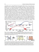
Figure 4.1
Early version of a paint inspection system that looks for cosmetic defects
on auto body immediately after paint spray booth.
Page 37
Figure 4.2
Cognex Vision system verifying and sorting foreign tires based on tread pattern
identification.
Stage 4 is characterized by technology transparency - the user does not know anything about it, other than that it is
useful. Most car drivers understand little about how a car operates, other than what it does when you turn the key.
Interestingly, when the car was a "stage 2" technology, a driver also had to be able to service it because of frequent
breakdowns experienced. Since then an infrastructure of service stations and highways has emerged to support the
technology. In stage 2 there were over 1100 car manufacturers in the United States alone! The industry consolidated as
it moved from stage 2 to stage 4.
Clearly, while some consolidation has taken place in the machine vision industry, there are still hundreds of players.
This is an indicator of more of a Stage 3 technology. This means that one should have some level of understanding of
the technology to apply it successfully. Machine vision is far from a commodity item. The first step is to become
informed - the very purpose of this book.
Page 38
Figure 4.3
Early system installed on a steel line by Opcon
designed to measure cylindrical property of billet.
It is not clear that machine vision as we have defined it will ever become transparently pervasive in our lives or truly a
stage 4 technology. The reality is that the underlying technology will definitely become stage 4 technology. The area
of biometrics that often uses the same computer vision technology is expected to become a major tool in accessing
automated teller machines, cashing checks, accessing computers, etc. There is no doubt there will be other markets in
which the underlying technology will become pervasive. For example, if the automobile is to ever achieve autonomous
vehicle status, computer vision in some form will make it possible.
Page 39
Figure 4.4
Adept vision-guided robot shown placing components on printed
circuit board.
4.1—
Human Vision versus Machine Vision
Significantly, machine vision performance today is not equal to the performance one might expect from an artificially
intelligent eye. One "tongue-in-cheek" analysis by Richard Morley and William Taylor of Gould's Industrial
Automation Section quoted in several newspaper articles in the mid-1980's suggests that the optic nerve in each eye
dissects each picture into about one million spatial data points (picture elements). Retinas act like 1000 layers of image
processors. Each
Page 40
Figure 4.5
Early RVSI (Automatic) system at end of stamping line examining hole
presence and dimensions to monitor punch wear (a) and example of data (b).
Page 41
Figure 4.6
Zapata system inspecting bottle caps to verify presence and integrity of liners
at rates of 2600 per minute.
layer does something to the image (a process step) and passes it on. Since the eye can process about 10 images per
second, it processes 10,000 million spatial data points per second per eye.
While today there are machine vision systems that operate at several billion operations per second, these still do not
have anywhere near the generic vision capacity of humans. Significantly, the specification of MIPS, MOPS, and so on,
generally has little relevance to actual system performance. Both hardware and software architectures affect a system's
performance, and collectively these dictate the time needed to perform a complete imaging task.
Based on our eye-brain capacity, current machine vision systems are primitive. The range of objects that can be
handled, the speed of interpretation, and the susceptibility to lighting problems and minor variations in texture and
reflectance of objects are examples of limitations with current technology. On the other hand, machine vision has clear
advantages when it comes to capacity to keep up with high line speeds (Figure 4.6). Similarly, machine vision systems
can conduct multiple tasks or inspection functions in a virtually simultaneous manner on the same object or on
different objects (Figure 4.7). With multiple sensor inputs it can even handle these tasks on different lines.
Some comparisons that can be made between human and machine vision are as follows:
Human vision is a parallel processing activity. We take in all the content of a scene simultaneously. Machine vision is
a serial processor. Because of sensor
Page 42
Figure 4.7
(a) Early RVSI (Automatix) system with multiple cameras inspects tie rod to
verify presence of thread, assembly, completeness and swage angle; (b)
with multiple cameras inspects tie rod to verify presence of thread, assembly,
completeness, and swage angle; (c) with multiple cameras to inspect tie
rods to verify presence of thread, assembly, completeness, and swage angle;
and (d) with multiple cameras to inspect tie rods to verify presence of thread,
assembly, completeness, and swage angle.
Page 43
Page 44
technology, information about a scene is derived serially, one spatial data point at a time.
Human vision is naturally three-dimensional by virtue of our stereovision system. Machine vision generally works on
two-dimensional data.
Human vision interprets color based on the spectral response of our photoreceptors. Machine vision is generally a gray
scale interpreter regardless of hue, based on the spectral response of the sensor world. Significantly, sensors exist that
permit viewing phenomenon beyond the range of the eyes (Figure 4.8).
Human vision is based on the interaction of light reflected from an image. In machine vision any number of
illumination methods are possible, and the specific one used is a function of the application.
Figure 4.8
Light spectrum.
Page 45
Figure 4.9
Rendering of eye
(courtesy of RVSI/Itran).
Tables 4.1 and 4.2 summarize the comparison between machine vision and human vision. A key difference is that
machine vision can be quantitative while human vision is qualitative and subjective.
The process of human vision begins when light from some source is reflected from an object. The lens (Figure 4.9) in
the eye focuses the light onto the retina. The light strikes pigments in the rods and cones, where a photochemical
reaction generates signals to the attached neurons. The neural network modifies these signals in a complex manner
before they even reach the optic nerve and are passed onto the occipital nerve, where cognitive processing of the image
starts. Generally speaking, early on we establish models of our surroundings and interpret what we observe based on a
priori known relationships stemming from learned models. Machine vision has a long way to go.
Page 46
Table 4.1 Machine Vision versus Human Vision: Evaluation of Capabilities
CAPABILITIES MACHINE VISION HUMAN VISION
Distance Limited capabilities Good qualitative capabilities
Orientation Good for two dimensions Good qualitative capabilities
Motion Limited, sensitive to image blurring Good qualitative capabilities
Edges/regions High contrast image re-quired Highly developed
Image shapes Good quantitative measurements Qualitative only
Image organization Special software needed: limited
capability
Highly developed
Surface shading Limited capability with gray scale Highly developed scale
Two-dimensional interpretation Excellent for well-defined features Highly developed
Three-dimensional interpretation Very limited capabilities Highly developed
Overall Best for quantitative measurement
of structured scene
Best for qualitative interpretation
of complex, unstructured scene
4.2—
Machine Vision Definition
What do we mean by machine vision? Distinctions are made between image analysis, image processing, and machine
vision. Image analysis generally refers to equipment that makes quantitative assessments on patterns associated with
biological and metallurgical phenomena. Image processing refers generally to equipment designed to process and
enhance images for ultimate interpretation by people. The instruments used to interpret meteorological and earth
resources data are examples.
Machine vision has been defined by the Machine Vision Association of the Society of Manufacturing Engineers and
the Automated Imaging Association as the use of devices for optical, noncontact sensing to automatically receive and
interpret an image of a real scene in order to obtain information and/or control machines or process.
Significantly, machine vision involves automatic image interpretation for the purpose of control: process control,
quality control, machine control, and robot control.
Page 47
Table 4.2 Machine Vision versus Human Vision: Evaluation of Performance
PERFORMANCE CRITERIA MACHINE VISION HUMAN VISION
Resolution Limited by pixel array size High resolution capability
Processing speed Fraction of second per image Real-time processing
Discrimination Limited to high-contrast images Very sensitive discrimination
Accuracy Accurate for part discrimination
based upon quantitative
differences; accuracy remains
consistent at high production
volumes.
Accurate at distinguishing
qualitative differences; may
decrease at high volumes
Operating cost High for low volume; lower than
human vision at high volume
Lower than machine at low
volume
Overall Best at high production volume Best at low or moderate
production volume
Figure 4.10
Functional block diagram of basic machine vision system.
Page 48
A fundamental machine vision system (Figure 4.10) will generally include the following functions:
Lighting. Dedicated illumination.
Optics. To couple the image to a sensor.
Sensor. To convert optical image to analog electronic signal.
Analog-to-Digital (AID) Converter. To sample and quantize the analog signal. (Note: some cameras have digital
outputs so a separate A/D function is not required.)
Image Processor/vision engine. Includes software or hardware to reduce noise and enhance, process, and analyze
image.
Computer. Decision-maker and controller.
Operator Interface. Terminal, light pen, touch panel display and so on, used by operator to interface with system.
Input-Output. Communication channels to system and to process.
Display. Television or computer monitor to make visual observations.
The fundamental machine vision functional block diagram of virtually all machine vision suppliers looks the same
(Figure 4.10). Significantly, each of the discrete functions described in this figure may have different form factors. For
example, the A/D converter could be a function on a frame grabber or image processing board, a part of the proprietary
design of a vision engine or integrated into the sensor/camera head. Similarly, the display may be a unit separate and
independent from the operator interface display or integrated with that display. The image processor/vision engine
could in fact be software that operates within the computer or an image processing board or a proprietary hardware
design. In other words, depending on the system and/or the applications one might observe different implementations
of the functionality depicted in Figure 4.10.
What happens in machine vision? It all starts with converting the optical picture to a digital picture. In general, the
systems operate on the projected image of a three-dimensional scene into a two-dimensional plane in a manner
analogous to what takes place in a photographic camera. Instead of film, a sensor acts as the transducer and when
coupled with an A/D converter, the system characterizes the scene into a grid of digital numbers (Figure 4.11). The
image information content at discrete spatial locations in the scene is derived in this manner.
One analogy is to consider the image as on a piece of graph paper (Figure 4.12) with each location mapped onto the
corresponding grid. This array has a finite number of discrete elements called picture elements, or pixels (also
sometimes called pels). The number of X and Y elements into which the image can be discretely segmented are called
resolvable elements. One definition of the resolution of a system is therefore the number of X and Y pixels. A pixel is
correspondingly the smallest distinguishable area in an image.
Page 49
Figure 4.11
Camera with analog-to-digital converter results in digital representation of image.
Figure 4.12
Mapping of three-dimensional scene into two-dimensional plane.
Page 50
The quantized information content in each pixel corresponds to intensity. This information is defined as a ''bit" and
relates to image brightness when digitized into a number of quantized elements:
For example, 2
4
= 16. In other words, the 4 bits corresponds to interpreting the scene as 16 shades of gray; 6 bits, 64
shades; 8 bits, 256 shades. In terms of shades of gray, a person is supposed to have an ability to distinguish a single
hue (color) into 60 or so shades. However, unlike people, who can interpret hues and therefore characterize as many as
4000 shades by hues, machine vision systems available today generally only interpret all hues into the shades of gray
defined by the specific system. In other words, they generally cannot distinguish an object's hue and can become
confused if two hues have the same gray value.
TABLE 4.3 Object Properties in Pixel Gray Value
Color
Hue
Saturation
Brightness
Specular properties
Reflectance
Texture
Shading
Shadows
Nonuniformities
Lighting
Optics/vignetting
Table 4.3 depicts the properties of an object that contribute to the value of the shade of gray at a specific pixel site. In
addition, this property can be influenced by the medium between object and illumination and object and sensor, by
filters between object and illumination and object and sensor, by optical properties such as vignetting and dirt on the
optics, and by sensor pixel sensitivity variations. Figure 4.13 reflects the digital representation of a scene, and Figure
4.14 depicts the digitally encoded values of the gray shades that are being fed to the computer, reflecting the properties
in one small section of the scene. In terms of resolution, the greater the resolving power of the system, the truer the
fidelity of the image the system receives as the basis on which to make decisions.
Page 51
Figure 4.13
Depiction of resolution/pixelation; digitally encoded values of
shades of gray
(courtesy of RVSI/Itran).
Figure 4.14
Reflects encoded gray values of small piece of picture
(RVSI/Itran).
Page 52
Figure 4.15
Resolution and image fidelity
(courtesy of General Scanning/SVS).
Figure 4.15 shows the impact of higher resolution to more faithfully reproduce the image for computer interpretation.
In practice the sensor and the time available on which to make a decision limit resolution. The application dictates the
complexity of the processing required and this in combination with the amount of time available and the resolution
dictates the computational power required.
In other words, compromises may be required (stemming from the amount of data generated by a sensor as resolution
increases) in computing power and time it takes to perform all the computations. In principle, however, the larger the
resolution of the sensor (Figure 4.16), the smaller the detail one can observe in the scene. Correspondingly, keeping
detail size the same, the field of view on which one can operate increases.
Figure 4.16
Resolution versus
field-of-view
(courtesy of General
Scan-ning/SVS).
Page 53
Figure 4.17
Neighborhood processing
(courtesy of RVSI/Itran).
The challenge in machine vision is the computational power required to handle the amount of image data generated:
256 × 256 × 30 ~ 2 MHz
512 × 512 × 30 ~ 8 MHz
These are 8-bit bytes if processing 256 shades of gray images. Data arrives at the rate of one pixel in every 100 or so
nanoseconds. This is why in the many machine vision systems, resolution is only nominally 512 × 512, and each
picture element in the image is assigned to either black or white. This significantly reduces the amount of data that has
to be handled.
Gray scale systems require far more computer power and algorithms for processing data. Conventional data-processing
computer architectures require 20 or more instructions for gray scale image acquisitions and a "nearest neighbor"
processing on one pixel (Figure 4.17). This refers to an operation in which a pixel's value is changed in some way
based on replacing that pixel with an altered value, where the basis for the alteration is derived from the values
associated with neighboring pixels.
Page 54
If a machine can perform two hundred million instructions per second, it will be able to perform this type of operation
at a rate of 10,000,000 pixels per second - a 512 × 512 image will take 20–30 milliseconds. The actual computational
requirements of an application are a function of image size, response times, number of processing steps required,
complexity of processing, and number of cameras. Actual processing can require 100–10,000 operations per pixel
depending on the requirements. Image preprocessing can be minimized by optimizing staging to eliminate positioning
uncertainty or other uncertainties stemming from shadows, highlights occlusions, and so on.
Systems for processing color images are another order of magnitude more complex. To minimize complexity, machine
vision systems generally operate on two-dimensional information. With certain lighting techniques, the three-
dimensional properties of an object can be inferred from a two-dimensional scene. For example, by examining how a
stripe of light bends over a three-dimensional object, a machine vision system can infer dimensional data and the
distance of an object. An alternate approach to obtain three-dimensional detail has been to employ two cameras and
use stereo correspondence analysis based on triangulation principles.
4.3—
Machine Vision Applications
Table 4.4 depicts the type of information that can be extracted and analyzed from an image of an object: spectral,
spatial, and temporal. The actual data operated on and the type of analysis that a machine vision system must perform
is a function of application, which includes task, object, and related application issues (material handling, staging,
environment, etc.). The task refers to:
Inspection
Gauging
Cosmetic (flaw detection)
Verification
Recognition
Identification
Location analysis
Position
Guidance
Tables 4.5 and 4.6 depict taxonomies of generic machine vision applications outlined in a study conducted at SRI
International by Charles Rosen in the late 1970s.
Gaging deals with quantitative correlation to design data, seeing that measurements conform to designs (Figure 4.18).
Cosmetic inspection (flaw detection) is a qualitative analysis involving detection of unwanted defects, unwanted
artifacts with an unknown shape at an unknown position (Figure 4.19).
Page 55
Figure 4.18
Perceptron on-line gauging system checking sheet metal assemblies for gap
and flushness.
Table 4.4 Hierarchy of Types of Visual Information Extractable from Image of Single
Object
Spectral
Frequency: color
Intensity: gray tones
Spatial
Shape and position (one, two and three dimensions)
Geometric: shape, dimensions
Topological: holes
Spatial coordinates: position orientation
Depth and range
Distance
Three-dimensional profile
Temporal
Stationary presence and/or absence
Time dependent: events, motions, processes
Page 56
Table 4.5 Machine Vision Applications: Inspection
Highly quantitative mensuration, critical dimensions: critical exterior and interior
dimensions of key features of workpieces
A. Qualitative-semiquantitative mensuration
1. Label reading and registration
2. Sorting
3. Integrity and completeness
a. All parts and features present; right parts
b. Burrs; cracks; warping; defects, approximate size and location of key features
4. Cosmetic and surface finish properties: stains and smears; colors, blemishes, surface
discontinuities
5. Safety and monitoring
Figure 4.19
ORS Automation machine vision system inspecting
faceplate of cathode ray tubes for imperfections.
Page 57
Figure 4.20
GS-1 system from MV Technology Ltd for in-line
automatic inspection and measurement of populated
SMT PCBS.
Verification is the qualitative assurance that a fabrication assembly has been conducted correctly (Figure 4.20).
Recognition involves the identification of an object based on descriptors with the object (Figure 4.21). Identification is
the process of identifying an object by use of symbols on - an object (Figure. 4.22). Location analysis is the assessing
of the position of an object (Figure 4.23). Guidance means providing adaptively positional information for feedback to
control motion (Figure 24).
Page 58
Figure 4.21
System that can recognize green
beans and distinguish them from
foreign objects such as stems.
Page 59
Figure 4.22
Early system from Penn Video used to identify different foam auto seats
based on dot matrix pattern.
Page 60