Handbook of Industrial Automation - Richard L. Shell and Ernest L. Hall Part 14 doc
Bạn đang xem bản rút gọn của tài liệu. Xem và tải ngay bản đầy đủ của tài liệu tại đây (691.44 KB, 42 trang )
operation. The only consistency is that the material
must follow the speci®c 1 > 2 > 3 routing. In these
applications, the APB can not only handle the physical
moves between cells, but can manage the storage of
WIP that will develop between cells as a function of
intercell variability.
In most APBs the use of closed system replenish-
ment rules provides an automatic kanban that throttles
the system from having a runaway cell. As a free side
eect, however, these systems can be tuned by the
addition of ``free'' totes (extra totes in the system for
use between cells). These free totes provide some inter-
nal slack to the strict kanban control, allowing cells to
operate more smoothly in the presence of brief inter-
ruptions in the planned continuous ¯ow.
For example, one cell may produce a product that is
placed in an empty tote and delivered to the next cell
for the next process operation. To perform the ®rst
cell's function, it needs raw materials, and an empty
tote in which to place the output to be transported to
the next cell.
The second cell may remove the product from the
tote, process it, and place it in a ®nished product tote
for delivery to a packaging station for shipment. The
empty tote created is then sent back to the ®rst cell for
replenishment.
Between each operation, the loads may need to be
stored to prevent work buildup at the workstation that
may make the station inecient. Then, when it appears
that the station will be able to accept the next load, the
system needs to get it out to the cell before it is needed
to prevent idleness.
The ¯ow of product from cell 1 to cell 2 and so on, is
balanced by the back ¯ow of empties to the sending
cells. If a backup stalls one of the cells, the back¯ow
stops, which in turn, stops the forward ¯ow of mate-
rial. This provides for a self-metering system that needs
little control logic to keep all cells operating in a
balance with the total system's capacity. The ability
of the system to keep running in lieu of single cell fail-
ures is then a function of the number of ``free'' totes
held in the system between each cell.
2.10.2 Computing Cycle Times
The throughput, or cycle time of AS/R systems has
been de®ned in numerous ways. There are techniques
such as activity zoning to attempt to improve the over-
all eciency of the device, but there are only a couple
of industry benchmarks for computing cycle times.
The best way of analyzing the capacity of a pro-
posed system is with a simulation of the system using
actual data representing material arrivals and disburse-
ments. In fact, the only way to analyze a side delivery
system with multiple input and output stations is with
a dynamic simulation.
An alternative manual method is to compute the
probable time to complete each class of move that
might be scheduled at each station, and then sum the
probability weighted average time for each move based
on expected activity. While this method does not
always expose system interferences due to contention
for resources caused by scheduling, it is a good ®rst
look at system capacity without the eort and expense
of simulation.
For end-of-aisle systems (input and output occurs at
one end of the AS/R system aisle) there are two meth-
ods that produce comparable results. The purpose of
approximating cycle time is, of course, to provide a
``®rst-pass'' analysis of the adequacy of a design, and
to allow a comparison of alternative solutions.
The ®rst solution is based on recommended meth-
ods developed and published by the Material Handling
Institute, Inc. (MHI) [7]. It refers to the calculation
procedures to compute the single cycle and dual cycle
moves typical of end of aisle systems (see Fig. 13).
The single cycle move is a complete cycle with the
AS/R system machine in a home or P&D (pickup &
deposit station) position, empty and idle. The single
cycle time is measured by computing the time to
move the crane to a rack location 75% of the length
of the aisle away from the home position, and 75% of
the height of the system above the ®rst level of storage.
In a 100-bay long, 12-tier-tall system, the crane would
Automated Storage and Retrieval Systems 653
Figure 13 Material handling institute AS/RS single cycle.
Copyright © 2000 Marcel Dekker, Inc.
leave the home position, travel to the 75th bay and
ninth tier. This is often referred to as the 75/75 posi-
tion.
The total single cycle time is then computed as two
times the time to make the 75/75 move, plus the time
required to perform two complete shuttle moves. A
shuttle move is the time required to extend the shuttle
fork under the load, lift it o the rack, and then retract
the shuttle with the load on board.
A caution in applying this algorithm: modern AS/R
systems have the ability to control acceleration and
vehicle speed as a function of whether the retriever is
traveling empty or with load. Therefore, true cycle
times for single or dual cycles must be computed
based on the speci®c performance parameters of the
product being analyzed.
The dual cycle, as de®ned by MHI is similar (see
Fig. 14). The time is based on the crane starting
empty at the home position. The cycle involves the
crane picking up a load at the home (0, 0) position,
taking it and storing it in the 75/75 position. The
crane then moves to the 50/50 position (50% of the
length of the aisle, and 50% of the height of the
aisle) to pick up a load. After picking it up, the crane
then moves back to the home position and deposits the
load picked up from the 50/50 position.
In summary, there are three crane moves and four
shuttle moves making up the dual cycle.
There are no speci®ed standards for the ratio of
single to dual cycle commands performed by a given
system. The use of input and output queuing con-
veyors can allow work to build up such that dual cycles
are performed a majority of the time. Obviously, dual
cycles are preferable to singles in that two loads are
moved per three crane moves, but response require-
ments often result in a series of single cycle moves to
process a sudden demand for output.
As a starting point, most planners will assume 30%
of the moves will be single cycle moves, with the
balance being duals.
Additionally, AS/R system performance is usually
enhanced through the use of velocity zoning of the
storage aisle. This is the practice of storing the fastest
moving inventory nearest the input/output station at
the end of the aisle. In practice, it is unusual for a
Pareto eect to not be present in the inventory activity
pro®le. This eect will signi®cantly impact the overall
requirements of the system design.
Using this rule of thumb to weight the single and
dual cycle move times, the expected loads moved per
hour (M) can be simply approximated as follows:
M 3600=0:30C
s
0:70C
d
where
C
s
Seconds required to perform a single cycle
move
C
d
Seconds required to perform a dual cycle
move
A second approach was more recently published
that more directly approximates the cycle times for
single and dual cycles of an end-of-aisle AS/R system.
It takes into consideration the eects of randomized
storage locations on cycle time and the probability of
being commanded to store or retrieve to any location
in the aisle [8]. It understates the overall capacity of a
crane if the vehicle uses higher speeds and/or accelera-
tions when moving in an unloaded condition. If used
uniformly to analyze all options, however, it is useful
for rough-cut analysis. These equations are
T
SC
T1 Q
2
=32T
p=d
T
DC
T=3040 15Q
2
À Q
3
4T
p=d
where
T maxt
h
; t
v
Q mint
h
=t
v
; t
v
=t
h
with
T
SC
Single command cycle time
T
DC
Dual command cycle time
T
p=d
Time to perform a pick up or drop o
shuttle move
t
h
Time required to travel horizontally from the
P/D station to the furthest location in the aisle
654 Parsley
Figure 14 Material handling institute AS/RS dual cycle.
Copyright © 2000 Marcel Dekker, Inc.
t
v
Time required to travel vertically from the P/D
station to the furthest location in the aisle
Again, this provides a single cycle and dual cycle esti-
mate, but makes no attempt to state how many loads
will be moved by the system per hour. The planner
must determine the mix of single to dual cycles. The
starting point, in lieu of other factors is 30% single,
70% duals. A ®nal rule of thumb for use in the feasi-
bility stage of project design is to only apply equipment
up to 80% of its theoretical capacity.
The important thing to remember is that all cycle
time estimates are just thatÐestimates. The technique
should be used to analyze the perceived eciency of
one concept or type of equipment over another. As
long as the technique is used identically to compute
throughput of all alternatives, it is an adequate tool
to make a ®rst comparison of alternatives. In all
cases, however, mission-critical systems should be
simulated and tested against real or expected transac-
tion data to ascertain actual system capacity to handle
activities in the real system.
2.10.3 System Justi®cation Based on Flow
Versus Static Costs
The rule of thumb is that if you put 15 engineers and
accountants in a room, you will produce 347 dierent
methods of computing the return on investment of a
proposed project. The fact is: justi®cation is simple. It
is a function of the computed payback period, the
capital available to fund the project, and the commit-
ment of management that the process the system will
support is a process that will support the vision of the
company into the foreseeable future.
The only factor that the planner can deterministi-
cally project is the computed payback period. The bal-
ance of a payback analysis becomes subjective unless
you realize that it is very dicult to justify any major
material handling investment unless it is part of an
overall process re-engineering eort.
There is a strong temptation to jump directly to an
analysis of alternatives by reducing the cost of a ware-
house system to the cost per storage location. Even if
the expected costs of labor, utilities, and facility space
are factored into the equation, this method will almost
always push the planner to the sutoptimal solution that
overly depends on manual (human) resources.
The inventory turns, and ¯exibility and responsive-
ness of the system, and the value adding capacity
added by the system must be factored into the equation
as well. Each of these factors must be approximated
for each alternative at varying degrees of activity. And
do not assume that each alternative has a linear
response to increases in activity rates.
For example, it is common to see planners consider
very narrow aisle (VNA) man-onboard order-picking
systems technology over AS/R systems. At low rates,
the cost per transaction is lower for VNA, primarily
because the capacity of the AS/R system is available,
but not being used.
As the activity rates approach the design capacity of
the AS/R system, however, the cost per transaction of
the VNA will actually increase and responsiveness
decrease because of the activity induced congestion.
(Remember the earlier reference to the attributes;
good, fast, and cheap). Add to the reality of these
systems the variability of nonautomated or semiauto-
mated man-to-load systems, and it becomes clear why
so many of these warehouses are not functioning today
as they were envisioned when built only a few years
ago.
The raw numbers (averages) may not clearly show
the increased costs of VNA in this example. Only
through complete system analysis can a correct decision
be based, and this usually involves simulation.
Simulation will not only help the planner understand
the intrinsic behavior of the plan, but only through
simulation will problems like gridlock be exposed that
are not illustrated by the average throughput numbers
often proposed in system concept summaries [9].
2.11 THE ROLE OF THE SUPPLIER IN
PLANNING AN AS/R SYSTEM
As much as the role of AS/R system has changed in the
way it is applied, the role of the AS/R system supplier
has changed to that of a consultative partner in the
project of determining the optimal system for the
application. The reason for this is related to the earlier
discussion about the ineectiveness of trying to solve
problems by breaking them apart into smaller subtasks
and components. Asking a supplier to simply respond
to concept speci®cations without having that supplier
participate in the overall analysis of the logistics pro-
cess will usually lead to a suboptimal concept proposal.
2.11.1 Objectivity of Solutions
There is still a belief that allowing the supplier in on
the initial planning is a bit like letting the fox design
the henhouse. In today's market, however, there is
simply too much information being exchanged to ser-
Automated Storage and Retrieval Systems 655
Copyright © 2000 Marcel Dekker, Inc.
iously believe that a single supplier could substantially
in¯uence a project team to only consider one oering.
2.11.2 Real-Time Cost Analysis
There are multiple bene®ts from involving the supplier
in the planning and analysis process. To begin, if the
budget is known by everyone, the supplier, who works
with the technology every day, is in a good position to
keep the team on track by pointing out the cost impact
of ``features'' that may not be economically feasible.
2.11.3 Use of Standardized Products
More speci®cally, the supplier will be in a role to help
the team understand the application of the technology,
including the use of standardized componentry
designed to reduce the custom engineering costs of a
new design.
Standardized products are often criticized as a sup-
plier trying to hammer an old solution onto your pro-
blem. In fact, standardized products usually oer a
wider set of standard functionality and variability than
most custom engineered solutions. If the planner is able
to use standardized solutions for the AS/R systems piece
of the plan, substantial cost reductions can be realized in
both engineering and total project cycle time.
Reduction in project cycle time is often an over-
looked opportunity. If you consider that many projects
are approved only if they pay for themselves in 30
months or less, a reduction in project implementation
time of 3 months (over other alternatives) nets you a
10% savings by giving you the system sooner. The
sooner you start using it, the sooner the returns from
the investment start to come in.
2.11.4 Performance Analysis and Optimization
Another role of the supplier as a member of the team is
the ability to use supplier-based simulation and analy-
sis tools for rough-cut analysis and decision making.
For example, a common assumption is that the fastest
crane will make a system faster and more responsive.
There is a tradeo of cost for speed, but more speci®-
cally, there are system operational characteristics that
will limit the ability to eectively use this speed. A
person who does not work with the application of
this technology on a regular basis will often miss the
subtleties of these design limits.
In a recent analysis, one supplier oered an 800 ft/
min crane for use in an asynchronous process buer.
The crane could start from one end of the system,
attain the top speed, slow down and accurately posi-
tion itself at the end of the 130 ft long system.
However, the average move under the actual design
of the process was less than 18 ft, with an estimated
standard deviation of less than 10 ft. This means that
97.7% of the moves will be less than 38 ft. The accel-
eration and deceleration rates were the same across all
speed ranges, but the cost of the 800-fpm drive was
wasted since the crane would only attain speeds of
less than 350 ft/min on 98% of its moves. The cost
dierence between a 350 ft/min crane and an 800 ft/
min crane will approach 21%.
2.12 CONCLUSION
The technology of AS/R systems has been reinvented
in the last 10 years. As part of a strategically planned
process, it can eectively serve to free up human
resources to other value-adding operations.
The trend in application is towards smaller, more
strategically focused systems that are located much
closer to and integrated with the ¯ow plan of speci®c
processes. While large systems are still being designed
and justi®ed, these systems are less common that the
small systems being installed within existing facilities
without modi®cation to the buildings (see Fig. 15).
The use of standardized system components has
reduced the manufacturing and engineering costs of
custom engineered, ``one-o '' designs, allowing plan-
ners a broader range of opportunity to use better,
faster more reliable and productive equipment in the
process of buering the material ¯ow.
To fully exploit the opportunity for improvement,
the planner must evaluate the entire process before
simply specifying a storage buer. Use of the supplier
656 Parsley
Figure 15
Copyright © 2000 Marcel Dekker, Inc.
in the planning process will improve the quality of
the recommendation for improvement, and will insure
that solutions proposed are optimized, workable, and
correct in terms of cost, schedule and overall system
performance.
REFERENCES
1. Considerations for Planning and Installing an
Automated Storage/Retrieval System. Pittsburgh, PA:
Automated Storage/Retrieval Systems Product Section,
Material Handling Institute, 1977.
2. PM Senge. The Fifth Discipline. New York: Currency
Doubleday, 1990.
3. DT Phillips, A Ravindran, JJ Solberg. Operations
Research Principles and Practice. New York: Wiley, 1976.
4. JM Apple Jr, EF Frazelle. JTEC Panel Report on
Material Handling Technologies in Japan. Baltimore,
MD: Loyola College in Maryland, 1993, p 29.
5. RE Ward, HA Zollinger. JTEC Panel Report on
Material Handling Technologies in Japan. Baltimore,
MD: Loyola College in Maryland, 1993, p 81.
6. Applications Manual for the Revised NIOSH Lifting
Equation. Pub no 94-110, U.S. Department of
CommerceÐNational Technical Information Service
(NTIS), Spring®eld, VA, 1994.
7. JM Apple. Lesson Guide Outline on Material Handling
Education. Pittsburgh, PA: Material Handling Institute,
1975.
8. JA Tompkins, JA White. Facilities Planning. New York:
Wiley, 1984.
9. N Knill. Just-in-time replenishment. Mater Handling
Eng. February: pp 42±45, 1994.
Automated Storage and Retrieval Systems 657
Copyright © 2000 Marcel Dekker, Inc.
Chapter 7.3
Containerization
A. Kader Mazouz and C. P. Han
Florida Atlantic University, Boca Raton, Florida
This chapter reviews the design, transportation, and
inventory of containers. Container design is a primary
aspect of the handling and dispatching of containers.
An ecient container design will keep adequately the
quality of the product being carried. Two issues iden-
ti®ed at the design stage are quality and economic
issues. An oine quality control program will enhance
the design and usage of the container. Section 3.1 of
the chapter will focus on the design. In this situation
we will provide guidelines to performing a design
experiment on a dunnage, a plastic container mainly
used in the automobile industry to transport parts.
Similar approaches could be used design corrugated
boxes or any other type of container. Section 3.2
focuses on statistical modeling of container inventory
control in a distribution network. Example practical
problems are included for an automobile maker and
a fresh fruit company.
3.1 EXPERIMENTAL APPROACH TO
CONTAINER DESIGN
First the issue of design of containers is addressed. The
approach is developed to determine an optimal con-
tainer design, to eventually realize a durable container.
An analysis and development of a design experiment is
performed to identify the major controllable variables
to perform a statistical signi®cance analysis on dier-
ent containers. A container is modeled using ®nite-ele-
ment techniques and tested to determine its durability
under simulated conditions. A database is developed to
help engineers to choose an optimal container design.
The database includes the choice of structures, mate-
rial process, wall thickness, shipping conditions, and
any combinations of these. The method developed
has been tested with dierent plastics using an illustra-
tive example.
3.1.1 Introduction
With the increasing competition in industry more and
more factories are taking a closer look at material
handling for ways of cutting expenses. Container
design, because it is only an auxiliary part of the pro-
duct, has not received enough attention. Often contain-
ers are designed according to experience. As a result,
the container is either too strong so that its life is much
longer than the life of the product contained and there-
fore adding unnecessary cost, or too weak, causing
product damage.
3.1.2 Procedure
Durability may be de®ned as a function of dierent
variables. These variables may or may not have a
great eect in the durability of the container. Once
these variables are identi®ed, a design of experiments
is performed. A design experiment is a test or series of
tests in which purposeful changes are made to the
input for changes in the output response. To use
the statistical approach in designing and analyzing
659
Copyright © 2000 Marcel Dekker, Inc.
experiments, an outline of a recommended procedure
is described in the sections that follow.
3.1.3 Choice of Factors and Levels
Close attention must be paid in selecting the indepen-
dent variables or factors to be varied in the experiment,
the ranges over which these factors will be varied, and
the speci®c levels at which runs will be made. Thought
must also be given to how these factors are to be con-
trolled at the desired values and how they are to be
measured. Variables which have a major eect on the
durability of the dunnage are the material, the process
used to produce the dunnage, the nominal wall thick-
ness, the load applied, and the ambient temperature.
The ®rst three are controllable variables and the other
two are uncontrollable. The material may be limited to
HDPE (high-density polyethylene), POM (acetal), or
ABS (acrylonitrile butadiene styrene). Loads may be
static to simulate the stacking of dunnages and impact
loads or dynamic to simulate the transportation of
parts via train, truck, or ship. Temperature conditions
may be studied at À208F, 688F, and 1008F and the
process reduced to four methods; vacuum, injection,
rotational forming, and injection molding.
3.1.4 Choice of Experimental Design
The choice of design involves the consideration of
sample size, the selection of a suitable run order for
the experimental trials, and the determination of
whether or not blocking or other randomization
restrictions are involved. For this experiment it is
known at the outset that some of the factors produce
dierent responses. Consequently, it is of interest to
identify which factors cause this dierence and the
magnitude of the response. For example, two produc-
tion conditions A and B may be compared, A being the
standard and B a more cost-eective alternative. The
experimenter will be interested in demonstrating that
there is no dierence in strength between the two con-
ditions. Factorial design can greatly reduce the number
of experiments performed by looking at which combi-
nations of factors have a greater eect in the durability
of the dunnage.
3.1.5 Performing the Experiment
Using computer-aided design CAD and ANSYS
(®nite-element software) a model of the dunnage is
constructed. The name ®nite element summarizes the
basic concept of the method: the transformation of an
engineering system with an in®nite number of
unknowns (the response at every location in a system)
to one that has a ®nite number of unknowns related to
each other by elements of ®nite size. The element is the
critical part of the ®nite-element method. The element
interconnects the degrees of freedom, establishing how
they act together and how they respond to applied
actions. A plastic quadrilateral shell may be used as
an element. This element has six degrees of freedom
at each node (translation and rotation), plasticity,
creep, stress stiening, and large defection capabilities.
Because of the incompleteness of current data in
service life prediction, some tests are necessary to set
up an engineering plastics durability database. A non-
destructive experiment is performed on the dunnage.
This experiment measured the de¯ection of the dun-
nage under dierent loading. The de¯ection is mea-
sured at several sections, in order to make sure that
the model constructed on ANSYS correlates to the
actual one. Theoretical results obtained from the com-
puter model are used to verify the experimental results.
Once the model in ANSYS is veri®ed, the study under
dierent loading conditions starts. Furthermore the
ANSYS model can be brought to failure. Failure
occurs when the stress level of the dunnage model is
higher than the tensile yield stress. Stresses higher than
this will cause permanent plastic deformation.
3.1.6 Data Analysis
Statistical methods provide guidelines as to the relia-
bility and validity of results. Properly applied, statis-
tical methods do not allow anything to be
experimentally proven, but measure the likely error
in a conclusion or attach a level of con®dence to a
statement. There are presently several excellent soft-
ware packages with the capability to analyze data for
the design of experiments. With the help of statistical
data on the durability of a speci®c dunnage and
the results of the ANSYS model, an optimal decision
can be made regarding the durability of the
dunnage.
3.1.7 Database
A database is used to generate the decision support
system. A ¯owchart of the dunnage durability data-
baseisshowninFig.1.Theuser-friendlyprogram
guides the user where data needs to be input. Help
menus are available at any instant of the program.
The output comes in the form of a report that shows
the durability of the dunnage under the speci®ed con-
660 Mazouz and Han
Copyright © 2000 Marcel Dekker, Inc.
FactorsandlevelsofstudyareshowninTable1.
Levels were set to cover a wide range of possible
scenarios of what the dunnage may undergo. The
result is a factorial system of 3
2
by 4
3
. This means
that two factors are at three levels and three factors
area at four levels. A randomized factorial design
was performed to obtain the set of experiments.
Randomization is the corner stone underlying the
use of statistical methods in experimental design. By
randomization it is meant that both the allocation of
the experimental material and the order in which the
individual runs or trials of the experiment to the
performed are randomly determined. By properly
randomizing the experiment, the eects of extraneous
factors that may be present are ``averaged out.'' The
randomizedfactorialdesignisshowninTable2.
A small section of the dunnage meshed in ANSYS is
showninFig.4.The®nite-elementmethodsolvesfor
the degree-of freedom values only at the nodes so it
will be convenient to increase the number of elements
in the critical areas of the container. ANSYS will pro-
vide at each node information regarding de¯ection,
stresses, and forces.
The ANSYS model was simpli®ed to make it fail
sooner than the actual container. After performing
the nondestructive experiment, results were compared
662 Mazouz and Han
Figure 2 CAD drawing of a dunnage.
Figure 3 Vibration and impact test.
Copyright © 2000 Marcel Dekker, Inc.
A distribution network identi®es a list of supply
sites and destination sites connected by routes. When
reusable containers are used in a distribution network,
the containers are required to ¯ow through road net-
works carrying the materials in demand. After trans-
portation, the containers are not necessarily returned
to the supply site. The containers can be sent directly
to container inventories of the destination sites for
future use.
A container inventory transportation network can
be classi®ed as either a closed system or an open sys-
tem. The closed system is a network in which the total
number of containers in the system does not change.
The open system is a network in which the total num-
ber containers changes. A transportation network can
also be classi®ed as a balanced or unbalanced system.
In a balanced system, the container inventory at each
site is balanced, meaning that the number of containers
shipped out by demand of a particular site is equal to
the number of containers returned. The inventory level
of containers remains unchanged at each site.
In an unbalanced system the inventory at some
sites will keep increasing or decreasing. There are two
reasons why a system can be unbalanced. One is the
number of containers broken during usage. We have to
add new containers into the system to compensate for
broken containers. The other reason is that the
demand shipment and the return of containers are
not equal for some sites. After a period of time, these
sites will have extra containers or will have a container
shortage. If the system is a closed system, the total
containers in the system will still be kept the same.
Therefore, we can ship containers to the sites with
container shortages from the sites with extra contain-
ers. The redistribution of the containers within such an
unbalanced system to make the containers available at
every site is essential to the performance of the whole
system. Closed unbalanced transportation systems are
the subject of this section.
When materials are transported between sites, the
container inventory levels at each site will change. The
container inventory control in a large transportation
system is a type of network-location-allocation pro-
blem. The demand pattern of the containers is similar
to the demand pattern of the materials. As with any of
the other inventory items, container inventory also has
its carrying cost, shortage cost, and replenishment cost.
The container's carrying cost, shortage cost, and
replenishment cost should be included into the total
cost of the distribution network.
Obviously, if there are not enough containers in the
network, it will cause transportation delays. However,
using more containers than necessary results in higher
initial investment and carrying costs. One of the funda-
mental problems of distribution network optimization
is to know how many containers should be maintained
in a particular system to make it ecient and eco-
nomic. On the other hand, although there are sucient
containers in a system, if they are not located at proper
sites, they are unavailable to the system at the moment
when they are required. This will also cause transpor-
tation delays or give up optimal routes. An ecient
way at reduce container inventory levels is to redistri-
bute the empty containers to appropriate sites at
appropriate times. The more frequently we redistribute
empty containers, the lower the container inventory
level that can be expected in the system. However,
the cost for container transportation increases at the
same time.
An additional focus is when and how to redistribute
empty containers in the system to reach the lowest
total cost. How to satisfy the requirement of transpor-
tation and maintain a minimum amount of container
inventory are common issues in analyzing such a trans-
portation system.
In this section we study the methods to minimize the
total cost of a transportation distribution network. We
use CIRBO as an acrony for Container Inventory
contRol in a distriBution netwOrk.
3.2.2 Reusable Container Inventory Control in a
Distribution Network
Reusable container inventory control in a distribution
network presents the combination of the characteris-
tics found in the transportation network system and
the inventory control system. It deals with not only
the inventory control but also the transportation
systems management. In fact there are three major
issues aecting the total cost considered here:
1. Optimal supply site selection for the commodity
in demand
2. Control policy selection for the container inven-
tory system
3. Optimal empty container redistribution
method.
In most cases, the demand and transportation time are
probabilistic. Issue 1 and issue 3 are transportation
problems with probabilistic demands. Issue 2 is a
special inventory control problem. If the system has
in®nite containers or if the containers are not used in
the material transportation, this system becomes a
pure transportation problem.
664 Mazouz and Han
Copyright © 2000 Marcel Dekker, Inc.
On the other hand, if the optimal routes have been
selected for commodity shipment, the system degener-
ates into a problem of multiple inventory control and
container redistribution in a distribution network. In
this case the system performance is totally dependent
on the inventory policy or the container management.
Analyzing such a system will clearly demonstrate how
container management aects the performance of a
transportation system.
The framework of this section is to develop a simu-
lation modeling procedure and address common pro-
blems of CIRBO systems. We ®rst de®ne the CIRBO
problem and describe dierent inventory policies.
Then, the simulation models for CIRBO are created
using SIMAN
#
simulation language. A simulation
code generator (SCG) system is then developed using
SIMAN as a target program to systematically generate
a CIRBO model based on a set of input conditions.
The SCG itself is implemented by C language in
an object-oriented window environment. The resultant
framework is reusable, extendible and user friendly.
3.2.3 CIRBO Model Development
There are two steps in developing the CIRBO model.
First, mathematical models are developed to describe
the distribution network. Then a computer simulation
code is generated. The mathematical models supply a
theoretical foundation, while the simulation code
creates a simulation model based on the user input
speci®cations.
3.2.3.1 System Outline
Assume a typical transportation network with reusable
containers which consists of m roads linking each site.
Each site could be a commodity supply site and/or a
commodity demand site. Each demand site can receive
a commodity from multiple supply sites and each sup-
ply site can oer commodities to dierent demand
sites. On each node, there can be a container inventory
and commodity inventory, and it can also generate
demand for commodities.
Each supply site contains both a commodity inven-
tory and a reusable container inventory. The commod-
ity is contained in reusable containers and then
transported by some method (airplane, ship, truck,
or train) among these sites.
When one site in the network requires materials, it
looks for supply sites from all other sites in the trans-
portation system. Some priorities for supply sites will
be selected according to speci®c transportation rules.
Here the rules should concern many features, such as
transportation cost, material availability, container
availability, material inventories, and container inven-
tories for possible future demands, etc.
When the selected site has adequate commodity and
containers available, the transportation takes place.
However, if the commodity or container is not avail-
able at the selected site, the demand has to be sent
to the secondary sites for supply. If, in some case,
that demand cannot ®nd adequate supply in the
whole system, it causes an unsatis®ed demand. A
penalty will occur.
From the above statements, we can see that there
are two main issues in the transportation network.
They are commodity transportation and container
management. In container management, the issues
that need to be concerned are container inventory
policies (when and how much of a replenishment
should be made) and empty container redistribution
(how a replenishment should be made). Actually, we
can decompose the whole problem into three
subissues:
1. Optimal schedule and route plan to minimize
the total cost for commodity transportation
2. Optimal container inventory control policy to
minimize the holding cost, shortage cost, and
redistribution cost
3. Optimal redistribution route selection to mini-
mize unit redistribution cost.
A network transportation problem can be studied in
dierent ways. From the view of commodity demand
and supply, it is basically a dynamic transportation
problem. It mainly deals with the schedule and route
problem of material transportation. The container
availability and the container control policy can be
handled as constraints for route and schedule optimi-
zation.
On the other hand, from the view of containers, the
problem can be described as a multiple inventory con-
trol problem. The problem deals with the holding cost,
the shortage cost, and the redistribution cost for the
reusable container inventory in the system. The com-
modity transportation aects the container demand
pattern, the lead time and the shortage cost of the
container inventory. The redistribution of containers
in a multiple inventory is another dynamic transporta-
tion problem. The cost of this transportation can be
calculated and added to the total cost as replenishment
cost. In this section, we discuss this problem from the
view of containers.
Containerization 665
Copyright © 2000 Marcel Dekker, Inc.
3.2.3.2 Dynamic Transportation Models
If containers are not used, or there are in®nite contain-
ers in each site, we never need to worry about con-
tainer availability. Distribution networks with
reusable containers become a pure dynamic transpor-
tation system. The issue becomes that for each
moment, the ¯ow of commodity from various sources
to dierent destinations should be selected to minimize
the total cost. The total cost consists of three parts:
transportation cost, holding cost for commodity wait-
ing in supply nodes, and penalty for unsatis®ed
demand.
3.2.3.3 Container Inventory System Analysis
There are two major issues in a transportation system
with reusable containers. The ®rst issue is to de®ne
how many containers should be invested in the system
to make it economic and ecient. Another issue is to
®nd the method to manage these containers to make
them available when a supply site needs them. To high-
light the eect of container and the eect of inventory
policy, we assume that the optimal transportation
route for commodity delivery has already been selected
using some dynamic transportation solution method.
If this optimal plan cannot be executed, the reason for
that must be caused by the container shortages at some
nodes. The dierence between the optimal plan and
suboptimal transportation plan is the eect of con-
tainer availability.
3.2.3.4 Redistribution Modeling
In CIRBO the unit cost for replenishment depends on
how the redistribution route is selected. Also a cost
matrix form can be constructed. The issue is that we
want to ®nd the optimal transportation plan to satisfy
the requirement of distribution and to minimize the
redistribution cost.
3.2.3.5 Statistical Modeling and Optimization
of the Container Inventory Control
Based on the mathematical models of the CIRBO
system, the system performance measurement and
various controllable variables can be identi®ed.
However, it is still very dicult to ®nd the optimal
solution using these models for such a complicated
problem, especially when the system is a probabilistic
system. A statistical systems modeling approach is
therefore recommended as a tool to analyze such
systems.
The ®rst consideration in building a simulation
model is to specify the goals or the purpose of the
model. In the CIRBO system analysis, we can optimize
the number of containers in the system by:
1. Minimizing the total cost, or
2. Reaching a speci®ed service level, or
3. Reducing the time of redistribution of empty
containers, etc.
Here, item 2 (service level) or item 3 (time of redistri-
bution) can be the focus of study. However, they do
not indicate the overall performance of the system.
Take the service level as an example, in order to
improve the service level, one of two methods can be
used. The ®rst one is to increase the number of con-
tainers in the system if the container carrying cost is
small. The other method is to reduce the time period
between the container redistribution if the redistribu-
tion cost is minimal. High service level is merely a
measurement of the system performance. However, it
makes no sense to seek high service levels without con-
cerning the total cost of the system.
A statistical systems modeling method is used in this
section. The key issue to make the simulation technol-
ogy more acceptable is to make the simulation process
signi®cantly easier to learn and use. Here the simula-
tion process includes not only the model building but
also the experimental design and data analysis.
3.2.4 Case Studies
In this section, we present two case studies. One case
study is performed for an automobile manufacturer
and the another one is conducted for a fresh fruit
company.
3.2.4.1 Modeling of a Transportation System
for an Automobile Maker
Problem Description. The transmission and chassis
division of an automobile manufacturer manages the
transportation of a large number of automobile com-
ponents and subassemblies. Reusable containers are
employed in the component subassembly transporta-
tion system. One of these systems is the Mexico±
Canada route. This route includes a main plant in
the United States, denoted US, two plants in Mexico
(MF1 and MF2) and another plant in Canada (CN).
Car parts are shipped from US to MF1. After some
part assembles are performed at MF1, containers are
needed to ship these assembled parts to MF2. The
extra empty containers will be shipped back to US.
666 Mazouz and Han
Copyright © 2000 Marcel Dekker, Inc.
More assembly work will take place at MF2. After
that, they will be shipped to CN and then back to
US using the amount of containers.
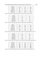
The demand from each plant and the average time
the containers spend in each plant, and delays on the
board of customs and on the road are listed in Table 3.
The time spent for each period is a random variable, and
these follow a normal distribution with the variance of
6 0:1 to 0.2 days. This system has a ®xed schedule and
transportation route. The plants usually work 5 days a
week without holidays, and there are dierent holiday
schedules in the United States, Canada and Mexico.
During weekends and holidays, the plants only receive
trucks but do not send any trucks out.
The automobile manufacturer is very interested in a
decision support system that can study the eects of
the number of containers in the transportation system.
The ideal decision support system should represent the
current transportation system and be able to stimulate
several proposed changes. It should also be able to
trace the availability of containers at a given moment
in each plant. Dierent container management and
optimization methods should be tested with various
numbers of containers in the system.
This is a typical case of the CIRBO that has four
sites with a ®xed route and a ®xed schedule. The
demand size is also known. In this case, all the factors
in the material transportation problem are ®xed and
given. We can concentrate on the container inventory
control problem. The system's variables are the num-
bers of containers in the system and the period of
redistribution.
Simulation Modeling and Optimization. Using the
SCG for CIRBO, we can create a SIMAN model for
the car manufacturer. In this case, the number of sites
is four. Each site has a unique supply. If there are not
enough containers available at the location when
needed, the truck has to wait until containers become
available. We give a very high penalty to the container
shortage because the manufacturer does not want this
to happen at any situation. The user can input initial
amount of containers for each location, then run the
simulation.
Using real demand data and assuring that there are
5000 containers in the system, the demand waiting time
and container availability at each plant is collected.
Figure6givestheaveragecontaineravailabilityfor
eachplantover5yearsandFig.7showstheaverage
demand waiting time at each plant in the 5-year period.
From Fig. 6 we see that most of the containers will be
accumulated at MF1 while other plants have a con-
tainer shortage. The demand waiting time in the
United States and Canada will increase, while the
time spent in the Mexico plant will decrease (see Fig.
7). There are two ways to avoid the accumulation of
containers and elongated waiting time: one is to
increase the container inventory and the other is to
rearrange empty containers.
For the purpose of comparing, we assume that there
is the same number of containers in the system, and we
redistribute empty containers annually to make the
container inventory level back to its optimum.
Running simulation for the same period, we have the
results shown that average container level keeping at
Containerization 667
Table 3 Data Prepared for Automobile Maker Transportation Systems
Time in Plant Time on Road
Demand
Mean Deviation Mean Deviation (Cont./day)
US 4.0 0.1
US±MF1 4.5 0.2 101
MF1 3.0 0.1
MF1±MF2 2.0 0.1 80
MF2 3.0 0.1
MF2±CST 0.5 0.1 80
CST 2.0 0.1
CST±CN 4.5 0.1 80
CN 3.0 0.1
CN±US 2.0 0.1 80
MF1±CST 0.5 0.1 0.5 0.1 21
CST±US 6.5 0.2 4.5 0.2 21
Copyright © 2000 Marcel Dekker, Inc.
marine-size shipping containers, and comes into a
port in the Gulf of Mexico. Upon arrival the con-
tainers are distributed from the port to customer
locations throughout the central part of the country.
There is an inherent problem in this fruit distribu-
tion system; the trade is unidirectional. The trade
imbalance between the United States and those loca-
tions from which the bananas come makes shipping in
both directions impracticable. Full containers are
imported from the source and empty containers must
be exported to replenish the container inventory. For
the system to be operated eciently, the boats return-
ing to Latin America must return fully loaded with
empty containers. An economical method is needed
for keeping the number of containers in the Latin
American port at a level high enough to ensure that
the boats leaving for the United States will be fully
loaded.
This dependence on return shipment of containers
means that a stable inventory of empty containers
has to be kept at the U.S. port when the ship
arrives. Unfortunately the U.S. side of the distribu-
tion system has a large amount of variability asso-
ciated with it. Many factors eect the amount of
time when a container leaves and returns to port
as outlined below:
1. The distance from the port to the customer's
location
2. The amount of time that the customer keeps the
container before returning it
3. The speed variability of the trucks and the ships
that deliver the containers
4. The day of the week that the container leaves
and returns to the port.
Currently, a high-level buer inventory is required
to overcome this variability so that any shortages of
empty containers can be made up with empty contain-
ers from the buer inventory. The size of buer inven-
tory is approximately one-half the capacity of a ship
used in the system.
Objectives. The cost of owning and operating this
fruit distribution system is tremendous. Each of the
shipping containers costs approximately $20,000.
Associated with each of the shipping containers is a
refrigeration unit that costs approximately $7000±
$10,000. In order for the refrigeration unit to operate
there must be a generator to power it while it is in port.
These cost approximately $5000 dollars per container.
Lastly, for the containers to be moved there must be
enough trailers. Trailers cost approximately $15,000
dollars each. The two container ships cost between
Containerization 669
Figure 8 Optimize the number of containers in system.
Copyright © 2000 Marcel Dekker, Inc.
20 and 40 million dollars each. This brings the total
equipment cost required to run the small system to the
neighborhood of 70 to 80 million dollars.
The area targeted for cost reduction is the excess
inventory of containers at the U.S. port. If the number
of containers maintained in the buer inventory could
be safely lowered by 10 containers, the company would
save approximately $350,000. It also saves the cost of
maintaining those containers and the associate equip-
ment over the life of the container.
On the other hand, with an investment of this size
the system should look for maximum return on invest-
ment. To maximize the return in such a system, the
system must be operated as eciently as possible.
Consider that a sucient buer inventory of empty
containers in the U.S. port will be used to ensure
against any possible loss of ship capacity. Current
practice is to keep an excessively large buer in con-
tainer inventory at the U.S. port so the ships can be
loaded eciently.
This is a closed-loop system. If a company owns all
the containers, there is no container replenishment in
the system. The carrying cost and shortage cost are
subject to control and are balanced. One of the policies
is that container shortage is not allowed. The problem
becomes that the company has to increase the number
of containers and carrying cost.
Another method is to use a leasing program to
reduce the number of containers the company owns,
and leased containers are used to meet peak demands.
This is another typical inventory control problem. The
total cost consists of the following:
1. Carrying cost: the cost of investment in
container inventories, of storage, of handling
containers in storage, etc.
2. Shortage cost: the cost of lost ship capacity
3. Replenishment cost: the cost of leasing con-
tainers.
These three costs are subject to control. Thus the goal
should be to optimize the total cost in such a way that
the ships are ®lled to capacity. The shortage cost will
always be less than the cost reduction of carrying cost
and replenishment cost.
Simulation Modeling. To ®nd the optimization solu-
tion, a simulation model has been constructed. The
model uses two ships to simulate the transportation
process and a network to simulate the distribution sys-
tem in the United States. In order to approximate the
actual system as closely as possible the original model
had the following characteristics and capabilities:
1. Two ships, each with a capacity of 100 contain-
ers, were used to move containers between two
ports. The ports were assumed to be 1500 miles
apart and the ships operated at a variable speed.
However, they work directly opposite each
other so that the two ships never arrived at he
same port at the same time.
2. The U.S. port was open for trucking 5 days a
week, but the ships operate 7 days a week. Thus
if a customer ordered a container of fruit and
requested that it be delivered by a speci®c time,
the delivery time was estimated. If the optimal
departure time for the truck was to be a
Saturday or a Sunday, the truck was forced to
leave on Friday.
3. If a ship was to fully load on a weekend it would
wait till the following Monday to allow trucks
that had returned over the weekend to load
their containers on the ship.
4. The speed of the trucks used to deliver the con-
tainers varied slightly with a normal distribu-
tion around 55 mph.
5. The amount of time that the trucker was
allowed to hold on to the container before
returning it was modeled with a normal distri-
bution with mean based on the distance from
the port.
6. The model can accept any kind of demand pat-
tern. The information used for demand was a
hypothetical demand as a function of distance
from the port. This model can also use history
data for the future forecast.
Control Policy 1: Company Owns All Containers.
When the company owns all the containers, no leasing
containers are added to the system. The reusable con-
tainers will remain unchanged in the system while the
container inventory at the U.S. port will ¯uctuate (see
Fig.9).
In cargo shipping the shortage cost of not having
enough containers is signi®cant compared with the
container carrying cost. This requires that a ship be
fully loaded when it leaves the port. The only way to
ensure that is to increase the containers in the system
(in the U.S. port as buer inventories).
Control Policy 2: Leasing Program to Reduce Buer
Inventory at the U.S. Port. When a leasing program is
employed, the total containers in the system will
change due to the leasing of containers. The inventory
¯uctuationisdepictedinFig.10.Shortagesarecovered
by leasing containers.
670 Mazouz and Han
Copyright © 2000 Marcel Dekker, Inc.
ACKNOWLEDGMENTS
The authors would like to acknowledge the Material
Handling Research Center at Florida Atlantic
University, The National Science Foundation, and
the Ford Motor Company for supporting this study.
And also acknowledge the work and assistance done
by the following students: P. P. Aguilera, Weiming
Feng and Pankaj Kanwar.
BIBLIOGRAPHY
KS Akbay. Using simulation optimization to ®nd the best
solution. IIE Solut May: 24±27, 1996.
ANSYS Manual Revision 4.3. Swanson Analysis Systems,
Inc., Feb 15, 1994.
CB Basnet, SC Karacal. Experiences in developing an object-
oriented modeling environment for manufacturing sys-
tem. Proceedings of the 1990 Winter Simulation
Conference, 1990, pp 477±481.
M Bogataj, L Bogataj. Inventory systems optimization for
dynamic stochastic and periodical demand. Eng Costs
Prod Econ 19(1±3): 295±299, 1990.
Bonelli P, Parodi A. An ecient classi®er system and its
experimental comparison with two representative learning
methods on three medical domains. Proceedings of the
Fourth International Conference on Genetic Algorithm.
R Belew, LB Booker, eds. 1991, pp 288±296.
MD Byrne. Multi-item production lot sizing using a search
simulation approach. Eng Costs Prod Econ 19(1±3): 307±
311, 1990.
M Chen, WP Chen, DC Gong, M. Goetschalckx, L
McGinnis. An AGV simulation code generator.
Proceedings of Material Handling Research Center at
Georgia Tech, Nov 1991.
C Das, SK Goyal. Economic ordering policy for determinis-
tic two-echelon distribution systems. Eng Costs Prod
Econ 21(3): 227±231, 1991.
N Erkip, WH Hausman, S Nahmias. Optimal centralized
ordering policies in multiechelon inventory systems with
correlated demands. Manag Sci 36(3): 381±392, 1990.
M Goetschalckx. Local User's Manual. Material Handling
Research Center, GIT, Atlanta, GA, 1991.
JJ Gregenstette, C Ramsey, A Schultz. Learning sequential
decision rules using simulation models and competition.
Mach Learn J 5: 1990, 335±381.
Hutchison, et al. Scheduling approaches for random job shop
¯exible manufacturing systems. Int J Prod Res 29(5):
1053±1067, 1991.
RG Lavery. A simulation analysis of the eects of transpor-
tation system parameters on inventory levels. Proceedings
of 90 Winter Simulation Conference, IEEE Service
Center, Piscataway, NJ, 1990, pp 908±910.
CJ Liao, CH Shyu. Stochastic inventory model with control-
lable lead time. Int J Syst Sci 22(11): 2347±2354, 1991.
GE Liepins, AW Lori. Classi®er system learning of Boolean
concepts. Proceedings of the Fourth International
Conference on Genetic Algorithms, R Belew, LB
Booker, eds, 1991.
M Montazeri, LN Van Wassenhive. Analysis of scheduling
rules for an FMS. Int J Prod Res 28(4): 785±802, 1990.
DC Montgomery. Design and Analysis of Experiments. 4th
ed. New York: John Wiley, 1996.
CD Pegden, RE Shanon, RP Sadowski. Introduction to
Simulation Using SIMAN. 2nd ed. McGraw-Hill, 1995.
D Porcaro. Simulation Modeling and DOE. IIE Solut
September: 23±25, 1996.
R Riolo. Modeling simple human category learning with
classi®er system. Proceedings of the Fourth
International Conference on Genetic Algorithms, R
Belew, LB Booker, eds, 1991.
LW Robinson. Optimal and approximate policies in multi-
period, multiplication inventory models with transship-
ments. Operat Res 38(2): 278±295, 1990.
SM Semenov. Determination of prior probabilities in
entropy models of a transportation system. Autom
Remote Control 50(10): 1408±1413, 1990.
T Shimada, Yamasaki, Ichimori. Introduction of Packaging
Design CAD System. Nippoh, 1990.
672 Mazouz and Han
Copyright © 2000 Marcel Dekker, Inc.
Chapter 7.4
Robotic Palletizing of Fixed- and Variable-Size/Content Parcels
Hyder Nihal Agha and William H. DeCamp
Motoman, Inc., West Carrollton, Ohio
Richard L. Shell and Ernest L. Hall
University of Cincinnati, Cincinnati, Ohio
4.1 INTRODUCTION
Warehousing is an expensive activity in the United
States, where it accounts for nearly 5% of the Gross
Domestic Product [1]. It can best be described as the
material handling functions of receiving, storing, and
issuing of ®nished goods. It is often viewed in industry
as a necessary evil, since it does not add value to a
product. However, the warehousing and distribution
functions are critical to a successful manufacturing
enterprise. Warehousing functions include information
processing, receiving, storage, order picking, palletiza-
tion, and shipping. The typical process for material
handling in a warehouse is as follows:
1. Items are received at a warehouse in multiple
pallet loads of identical items.
2. Loads are stored in the warehouse in some
planned con®guration.
3. When a customer's order arrives, an order
picker goes through the warehouse to pick the
desired items from separate pallets.
4. Items are routed to a load forming, palletizing,
or palletization, station where items of various
sizes and shapes are placed together on pallets
for shipment to the customer. Although this
palletizing operation has traditionally depended
upon human labor, recent eorts at automating
the palletization of parcels of mixed size and
shape have proven very successful.
There are several disadvantages to human palletiz-
ing. One is related to cost. Even the most motivated
and capable human can stack only about six parcels
per minute, i.e., one parcel per 10 sec. Another disad-
vantage is related to safety and workers' compensation
costs. A human who performs such a repetitive motion
is at risk for cumulative trauma disorders, such as back
and shoulder injuries. A typical human palletizer is
showninFig.1.
The advantages of robotic palletizing include: the
maximization of the usage of the pallet cube; the reten-
tion of knowledge about each parcel throughout the
distribution system; increased pallet load stability,
insurance of forming pallets in accordance with regu-
lations (i.e., not stacking poisons on top of food items,
and control of parcel fragility, which reduces waste.
Distribution centers are a necessary component in
the logistics system of most manufacturing industries
from food items, to dry goods, to computer or aircraft
engine components or machine tool parts. All distribu-
tors, including the defense industries, parcel industries,
and even medical industries, are potential users of a
robotic palletizing system.
Palletizing may be de®ned as arranging products to
form a unit load for convenient subsequent handling.
673
Copyright © 2000 Marcel Dekker, Inc.
where i 1; FFF; m. In this case, the total demand or
order is
D D
1
D
2
ÁÁÁD
m
The demand D
i
can be satis®ed by supplying any num-
ber of pieces, n
i
, of length, l
i
, of the strips of width, w
i
,
so long as the total lengths, L
i
sum to at least D
i
:
D
i
4 L
i
n
i
l
i
for i 1; 2; FFF; m
The demands are met by deciding on various slitting
patterns for the sheet of width W.
The jth slitting pattern is a way of dividing the
width, W, into the smaller widths, w
i
, for
i 1; FFF; m. This pattern is applied to a length
amount l
j
of the sheet:
W 5 n
1
w
1
n
2
w
2
ÁÁÁn
m
w
m
In the linear programming solution for this one-dimen-
sional noninteger stock-cutting problem, the matrix A
of the linear programming problem will have m rows
and a large number of columns, k. One column will
exist for each of the possible slitting patterns such
that each vector. N
i
n
1
; n
2
; FFF; n
m
of nonnegative
integers satisfying the following conditions.
W 5 n
1
w
1
n
2
w
2
ÁÁÁn
m
w
m
is a column of the matrix.
If X is a column vector of variables, each corre-
sponding to a slitting pattern, one for each column
of A, and if O is a row vector of all 1's, then the
linear-programming problem may be stated:
Minimize O
T
X x
1
x
2
ÁÁÁx
k
subject to
A
T
X N
where N is the column vector n
1
; n
2
; FFF; n
m
T
.
Variations of this problem occur in both noninteger
and integer forms. A linear-programming method may
be used to solve the noninteger problem. However, a
general diculty is encountered due to the very large
number of columns of possible solutions.
An integer problem is one in which the demands, D
i
,
are in integers and the variables, x
i
are restricted to
being integer. Rounded answers to the noninteger pro-
blem may be used to approximate the integer problem
solution.
4.2.2 Three-Dimensional Space Filling
The general problem of ®lling a three-dimensional
pallet with mixed-size parcels may be considered as
a mathematical problem of ®nding the space that is
®lling the pallet's volume. That is, N parcels must be
placed at positions (x
i
; y
i
; z
i
and the total volume ®lled
as completely as possible. Other problems of this
nature include the traveling salesman problem and
the game of chess. In general, these problems are called
NP-complete, that is, the computation time required
for an exact solution increases exponentially with N.
There is no method for ®nding an exact solution
except exhaustive search of all possible solutions.
Fortunately, modern arti®cial intelligent techniques
provide a means to obtain good solutions. An expert
system has been invented which provides solutions
which satisfy a set of rules and consequently provide
``good'' solutions. Furthermore, the approach can
be applied not only to single-product, mixed-layer,
column or prede®ned order of arrival palletizing, but
also to real-time, randomly arriving, and mixed-size
and content palletizing.
4.2.3 Factors Affecting Palletizing
From the above discussion, it is apparent that dierent
factors can aect the palletizing. The most important
are:
Pallet size. Generally, the larger the pallet, the better
are the chances of ®lling it eciently.
Product proliferation. Contrary to initial intuition, a
larger mix of sizes results in better load-forming
eciency, but at the expense of higher computer
run time. Stated dierently, if given an empty
space, the chances of ®nding a box that closely
®lls that space are improved when a greater vari-
ety of box is available, but more time is needed to
®nd that box. Note that boxes in an actual order
typically present some correlation; for example, it
is likely that there will be multiple boxes of a
certain type. Putting this information to use will
result in faster heuristics in generating load-
forming layouts.
Standards. Establishing box/carton standards is
essential because it greatly reduces the prolifera-
tion of boxes, thus allowing faster palletizing
algorithms.
Algorithm. Exact algorithms are time consuming to
the computer and dicult to implement.
Heuristics often result in ecient solutions in
relatively little time. Arti®cial intelligent methods
could result in a better performance, especially if
based on ecient heuristics.
Robotic Palletizing of Parcels 675
Copyright © 2000 Marcel Dekker, Inc.
Sequence of pick. Usually some pretreatment of the
boxes can assist in the speed of reaching a solu-
tion. In many cases, the pretreatment may not
even require additional work. For example, if
boxes are stored and issued in a sequence that
simpli®es the allocation of space to the boxes
(e.g., heavier boxes ®rst, light ones later, boxes
with identical sizes together, etc.), the solution
could be reached more quickly and easily.
Look ahead. The ability to look ahead can also be
used to speed up the search for space.
4.2.4 Palletizing of Identical-Size Parcels
Steudel [2] formulated the problem of loading uniform-
sized boxes as a four-stage dynamic program that ®rst
maximizes the utilization on the perimeter of the pallet
and then projects the arrangement inward. Correction
steps were given for the cases where the projection
resulted in overlapping boxes or in a large central
hole. Smith and DeCani [3] proposed a four-corner
approach to ®lling a pallet with identical boxes. The
procedure determined the minimum and maximum
number of boxes that could be placed starting from
each corner of the pallet, and then iteratively evaluated
the possible combinations that maximized the total
number of boxes on the pallet. Although no claim of
optimality is made in the paper, the results compare
favorably with exact methods.
The results of these patterns are often summarized
in a chart or table format. Apple [4] shows a set of
patterns and a two-dimensional chart developed by
the General Services Administration. The chart indi-
cates which pattern is recommended for each box
length±width combination. K. Dowsland [5] presented
a three-dimensional pallet chart that works for dier-
ent pallet sizes and indicates the sensitivity of the dif-
ferent patterns to variations in box sizes.
Researchers have tried to include some physical
constraints to the pallet-loading problem. Puls and
Tanchoco [6] considered the case where boxes are
handled by opposite sides, and they modi®ed the
Smith and DeCani approach to start with three cor-
ners, resulting in layouts that are built with guillotine
cuts. A guillotine cut is a straight line that cuts the
pallet or rectangle across, resulting in two subrectan-
gles. Carpenter and W. Dowsland [7] used a ®ve-area
approach that started from each of the corners and
from the middle to generate alternative layout pat-
terns. They evaluated the results based on criteria for
load stability and clampability, i.e., the ability to han-
dle the load with a clamp truck. It was deduced that
layouts comprising two areas are the most suitable for
clampability, but they also yield suboptimal utilization
of the pallet volume. K. Dowsland [8] investigated the
palletizing of boxes with a robot when it could handle
one, two or four boxes at a time, and sought to deter-
mine the minimum number of transfers.
Gupta [9] investigated the problem of determining
the pallet size when dierent box types are present, but
each pallet was to hold only a single type of box. The
problem was formulated as a two-stage mixed-integer
programming model. The ®rst stage seeks to optimize
the placement of boxes along one side of the pallet and
the second stage seeks to optimize the placement along
the other.
4.2.5 Palletizing Boxes of Variable Sizes
In situations involving high volume and high com-
plexity in terms of SKUs, the unit load to be formed is
expected to contain items of dierent sizes. This pro-
blem has received much attention in operations
research, especially under the closely related problems
of bin packing, knapsack, stock cutting and plane til-
ing. The general form of the problem is far from being
solved, and in fact can be shown to be NP-complete or
``hard.'' As an outline proof, consider the simpli®ed
case where all the boxes have equal height and width,
but dier in length. In this way, the problem is trans-
formed into that of ®nding the combination of box
lengths that best ®ll the pallet along its length. This
problem is equivalent to the one-dimensional bin-
packing problem, which was shown to be NP-complete
[10]. NP-complete refers to the class of problems for
which the only known solution involves enumerating
all the possible combinations, which is time prohibitive
because the number of alternatives grows combin-
atorially with increasing items. Consequently, these
problems are solved using heuristics or expert system
approaches, which yield nonoptimal solutions.
4.2.5.1 Heuristic Methods
Early eorts in the ®eld include the work of Gilmore
and Gomory [11, 12]. Their work investigated the two-
dimensional stock cutting problem, which arises when
a rectangular sheet of material is to be cut into smaller
rectangles of dierent sizes. The problem is analogous
to the palletizing of boxes of the same height. The
authors formulated the problem as a linear program
and suggested its solution by applying a knapsack
function at every pivot step, recognizing that it
would be computationally prohibitive.
676 Agha et al.
Copyright © 2000 Marcel Dekker, Inc.
Hertz [13] implemented a fast recursive tree search
algorithm that optimized the solution obtained by
using guillotine cuts. Note that this solution was not
necessarily optimal for the general solution. Herz's
algorithm assumed that the rectangles were positioned
in one orientation only. When this assumption is
applied to a box that can be rotated by 908, a duplicate
box with the length and width interchanged must be
created. Christo®des and Whitlock [14] also used a tree
search routine to attempt to ®nd the optimal layout
that can be obtained using guillotine cuts. They nar-
rowed the search space by eliminating redundant nodes
that arise due to symmetry, the ordering of the cuts,
and the location of the unused space. Applying this
procedure to a problem with 20 boxes, the solution
required 130 sec CPU time on a CDC 7600 computer.
Hodgson [15] combined heuristics and dynamic pro-
gramming in the solution of a two-dimensional pallet
layout. In this approach, the pallet is partitioned into a
rectangular area, constituted by the boxes that were
previously stacked starting from a corner, and into
an L-shaped strip, the candidate to be ®lled.
Dynamic programming was used to allocate boxes in
the two rectangular sections forming the L. This
approach restricted boxes to be placed in corridors
around the starting corner, but because of the simple
shape of the corridor, it resulted in signi®cantly fewer
partitions to be evaluated. Using the system, the opera-
tor interactively selects the ®rst box (typically a large
one) and the candidates for evaluation at each step. It
was reported that the eciency of packing increases
with increasing number of box types, but at the
expense of higher computer run time. In an adaptation
of Hodgson's work, designed to run on a microcom-
puter, Carlo et al. [16] used a simpler heuristic of ®tting
boxes in order of decreasing size. The procedure was
repeated by randomly varying the ®rst box to be place
and the orientation of the boxes, and the best result
was saved. When allowed to run 1 min on a microcom-
puter, the procedure resulted in area utilization of
about 95%.
Albano and Orsini [17] investigated the problem of
cutting large sheets of material and proposed the
approach of aggregating rectangles with an almost
equal dimension into long strips. Then, a knapsack
function was used to allocate strips across the width
of the sheet. The procedure was fast and was found to
result in very high area utilization (98%), especially
when applied to larger problems.
The problem of packing three-dimensional pallets
has been less thoroughly investigated. George and
Robinson [18] studied the problem of loading boxes
into a container. They developed a layer-by-layer
approach. Following the selection of an initial box,
all boxes with the same height become candidates,
and are ranked ®rst by decreasing width, second by
quantity of boxes of the same type, and ®nally by
decreasing length. The space in the layer is ®lled to
preclude a face with pieces jutting by starting from
one back corner and ®lling the area consistently to
have a straight or steplike front. When evaluating
their algorithm, George and Robinson found that it
worked better with actual than with random or deter-
ministic data, because actual shipments are likely to
have correlated values.
4.2.5.2 Arti®cial Intelligence Approaches
Mazouz et al. [19±21] at the University of Cincinnati
developed a rule-based expert system approach to
palletize boxes arriving in a random sequence. The
boxes are assigned locations on the pallet based on
the criteria of size, toxicity and crushability. Toxicity
is used to ensure that no toxic products are placed on
top of edible goods, and crushability is used to ensure
that no heavy loads are placed on top of soft or fragile
boxes.
The system was developed using the OPS5 expert-
system shell. The procedure ®rst divided the available
space into smaller discrete volume elements called
voxels. Second, a relation table was generated for the
box types in the bill of lading. The relations specify
how many of one box type need to be stacked in
order to obtain the same height as a stack formed
with dierent box types. These relations become
important in a layer approach to palletizing, in which
a ¯at surface is required to form the next layer. Third,
the boxes in the bill of lading were ranked according to
the criteria of toxicity and crushability. Finally, at run
time, for each box arriving on the conveyor, the pro-
cedure performed a search of the available space to
determine where to stack the boxes. Boxes that could
not satisfy the threshold requirement on toxicity and
crushability were placed on a queue pallet. The expert
system then downloaded the co-ordinates of the box to
the interfaced Cincinnati Milacron robot that per-
formed the palletizing. Test runs were made, and
required 40 min on a VAX 11/750 to generate a pattern
of 17 boxes arriving in a random sequence. Due to the
layered approach, the loads formed with the system
tended to be somewhat pyramid shaped, with larger
layers at the bottom and smaller on top.
Another expert-system approach was developed at
Georgia Tech University by Gilmore et al. [22] for use
Robotic Palletizing of Parcels 677
Copyright © 2000 Marcel Dekker, Inc.
in palletizing boxes in a Kodak distribution center. The
system was developed in Lisp-GEST and used a
semantic frame representation. It considered the cri-
teria of stability and crushability. The authors assumed
that the order would be known in advance and that the
boxes would arrive in a required sequence, and
approached the building of pallets by columns rather
than by layers. Using this approach, boxes of a similar
type were stacked vertically in columns, which are then
aggregated to form walls. A column approach is most
applicable when there is some correlation between the
boxes to be palletized. The column approach also
requires simpler algorithms than a layer approach.
The layer approach, on the other hand, provides stable
pallets, even if they are moved before being wrapped.
No report was provided on the speed or eectiveness
of the Georgia Tech model. Other approaches, such as
``simulated annealing'' [23], could also be considered.
The goal of building an intelligent system for palle-
tizing is fundamentally a problem of designing a deci-
sion maker with acceptable performance over a wide
range of complexity in parcel sizes and uncertainty in
parcel arrival sequences. Three approaches that have
potential for this intelligent system are:
Expert system as a decision maker for palletizing.
Fuzzy logic as the decision-producing element.
Neural networks as decision-producing elements.
The expert system uses a rule-based paradigm built
around ``If-Then'' rules. When the procedure works
forward from a sequence of ``If '' conditions to a
sequence of ``Then'' actions, it is called forward chain-
ing. Forward chaining requires a database and a set of
rules. This approach may be satisfactory for palletiz-
ing; however, it may be too slow for high-speed sys-
tems and has limited learning capability. Backward
chaining starts with a desired sequence of ``Then''
actions and works backward to determine whether
the ``If '' conditions are met.
The second approach deals with situations in which
some of the de®ning relationships can be described by
so-called fuzzy sets and fuzzy relational equations.In
fuzzy set theory, the element membership decision
function is continuous and lies between zero and
unity. Fuzzy set theory is useful in situations in
which data and relationships cannot be written in pre-
cise mathematical terms. For example, a ``good stack-
ing arrangement'' may be dicult to quantify but
provides signi®cant fuzzy information that may be
integrated into the decision-making process.
The third approach uses neural networks [24, 25].
With this approach, the input/output relationships
can be modeled as a pattern recognition problem
where the patterns to be recognized are ``change'' sig-
nals that map into ``action'' signals for speci®ed system
performances. This type of intelligent system can
recognize and isolate patterns of change in real time
and ``learn'' from experience to recognize change more
quickly, even from incomplete data.
4.3 CURRENT WORK IN AUTOMATED
PALLETIZING
An expert system is an excellent approach for palletiz-
ing, since it determines a solution that satis®es a set of
rules. In the current system, both parcels and pallet
space are represented by discrete volume elements, or
voxels, that are equal to zero if the space is empty or
unity if the space is full. The pallet is represented by a
``blackboard'' database that is changed as the pallet is
®lled. A bill of lading is used to represent the set of
parcels which are to be stacked. A database of content
information, size, fragility, etc. is also available for
each parcel type. In addition, a relational database is
formed, indicating size relationships between dierent
parcel types. For example, one relationship between
two small parcels placed together is that they could
form a base for a large parcel.
The goal of the expert system is to determine where
to place each randomly arriving parcel so that the
overall center of mass coincides with the center of
gravity or the pallet, and which satis®es all the other
rules. Examples of rules include:
Toxic substances should not be placed on top of
nontoxic products.
Boxes should not be crushed.
Glass containers should not be stacked on the
bottom.
Fracture or fault lines should not be generated.
Interlocking of parcels should be done, if possible.
This expert system has been implemented in OPS5
and used to control a Cincinnati Milacron industrial
robot, which was equipped with a vacuum gripper for
palletizing food parcels. For all the tests conducted, a
satisfactory stacking arrangement was obtained by the
expert system. The major drawbacks at this time are
computation time for the expert system. Speed of
the robot was also a problem in the original imple-
mentation; however, a higher-speed Atlas robot was
obtained. In the present research, we believe the
computation time will be decreased by simplifying
678 Agha et al.
Copyright © 2000 Marcel Dekker, Inc.
the algorithm, even though we expect to add additional
rules throughout the study.
A conceptual diagram of a robotic palletizing work-
cell is shown in Fig. 2. The top-center block, the visual
pallet, is the parent graphical user interface [26], the
nerve center of the software system. From it, all data is
relayed to and from the other software modules, such
as the interface module, the barcode dynamic linking
library (DLL), and the visual dynamic control inter-
face (DCI) [27] (a robot control interface). In the case
of a palletizing job of mixed size, or of content boxes
arriving in random order, the interface module would
come into play. As a job begins, the ®rst box is scanned
by the barcode reader. Then, the box SKU number is
passed through a visual pallet to the interface, where
its palletizing algorithm determines the box coordi-
nates on the job pallet or a queue pallet. This data is
passed through a visual pallet to a visual DCI which
instructs the robot to palletize the box, return to the
home position, and wait for the next instruction. After
sending the co-ordinates to a visual DCI, the system
determines if the palletizing algorithm has space on the
job pallet for a box in the queue pallet. If it determines
that it has adequate space, then it sends the data to a
visual pallet, which relays the coordinates to the robot
through a visual DCI. If there are not further instruc-
tions from the palletizing algorithm, a visual DCI
instructs, through the barcode DLL, the barcode
reader to scan the next box. The whole process starts
over and continues until the last box is palletized.
In the past several years, a PC-based version of the
expert system has been developed using the Windows
development tool Visual C
and integrated into the
graphical interface described in this chapter [28,29].
The development of this PC-based palletizing algo-
rithm was based on a revision of previously developed
palletizing software, not a line-for-line conversion.
Fortunately, all previously discovered rules can be
included in this new software. Because of the recent
improved processor capabilities in personal computers,
the time required to process a solution for a pallet load
has been greatly reduced. Processing time has been
Robotic Palletizing of Parcels 679
Figure 2 A conceptual diagram of a robotic palletizing workcell.
Copyright © 2000 Marcel Dekker, Inc.
reduced from 2.35 min per box using the previous
OPS5 expert system solution down to less than 5 sec
per box using the presently developed PC-based palle-
tizing solution. In light of these advancements, a
robotic palletizing application becomes an even more
attractive solution for every industry that utilizes this
type of material handling.
An expert-system or rule-based approachwas utilized
in the development of the palletizing algorithm. These
rules have been implemented directly in Clanguage. This
permits the system to run on a standard PC, and the code
is transportable and expandable. A ¯owchart of the pal-
letizing process is shown in Fig.3. The overall logic of the
expertsystemisshowninFig.4.Thepalletizingsoftware
system begins with system setup. This includes the ®rst
system setup in which pallet and box sizes are speci®ed
and thebill of lading speci®cation and relationship deter-
mination. Then the real time loop is started in which a
box is identi®ed, and a search for an acceptable space is
initiated. If an appropriate space is found, the co-ordi-
nates are communicated to the robot and the space sto-
rage is updated. This loop continues until all the boxes
from the bill of lading are placed. If space cannot be
determined for any boxes, they are placed on a queue
pallet. At the end of the loop, these boxes can be retrieved
and placed on the pallet.
Two types of inputs are required for the algo-
rithms. The ®rst is a database of dimensional sizes
and content information for the SKUs which are pos-
sible within the palletizing material handling stream.
A separate eort is required to ®lter this data to
ensure that all SKUs can be lifted by the particular
robot gripper and placed by an industrial robot.
Then, of the SKUs which can be handled, a relational
database is prepared which examines spatial relation-
ships, such as the number of boxes of one type that
would form a stable base for a given number of boxes
of another type. In addition, content-speci®c rules
may be determined, such as those related to fragility,
crushability, or contamination.
680 Agha et al.
Figure 3 A ¯owchart of the palletizing process.
Copyright © 2000 Marcel Dekker, Inc.
scaled-down unit smaller than the bottom layer along
the length or width. A set is valid when sucient quan-
tities of both
box1 and box2 types are available, and
the set dimensions, de®ned as
setLength and
setWidth, are such that the setLength does not
exceed the scaled pallet length (SPL), and the
setWidth does not exceed the scaled pallet width
(SPW). Since the code requires many
For loops and
If statements, to avoid confusion, only the coded used
to form these sets will be discussed. Each valid set is
stored in the data structure
sets_t. All the sets formed
are stored in an array of structures,
Sets[ ]. The size
of this array is de®ned in the header ®le.
struct sets_t{
char box1;
char box2;
char b1inLength;
char b1inWidth;
char b2inLength;
char b2inWidth;
char orient;
char setLength;
char setWidth;
}; struct sets_tSets[MAX_SETS];
In the sets_t structure, the variable b1inLength is
the number of boxes of type
box1 arranged along the
setLength and b1inwidth is the number of boxes of
type
box1 arranged along the setWidth. Similarly, the
variables
b2inLength and b2inWidth are for type
box2. In a set, the length of box1 is always parallel
to the
setLength, and the length of box2 may be
parallel or perpendicular to the
setLength. If length
of
box2 is parallel to setLength, then the variable
orient is de®ned as
ORIENT_LL. Otherwise, if box2 is
perpendicular to
setLength, then orient is de®ned as
ORIENT_LW.
4.3.2 Search for Space
When a box is identi®ed, a search for set relationships
and quantities is made. If a set relationships is found
with another box type and sucient boxes of that type
are in the bill of lading; then the box is placed, and
space is reserved for the new box type. Up to this
point, a framework has been constructed which will
allow for the necessary user input that will enable the
palletizing software to perform.
682 Agha et al.
Figure 5 The set formation process in which two boxes of type A are related to one box of type B in a length±width orientation.
Copyright © 2000 Marcel Dekker, Inc.
4.3.3 System Simulation and Performance
The results of this search are displayed as an output
®le showing box position, as shown in Fig. 6, or by
an equivalent graphical output, as shown in Fig. 7.
This type of output is very eective for displaying
database information in a more visually pleasing
and interactive form. Having both a box database
and a pallet database linked to the interface also
gives the user an inventory tool for the entire palletiz-
ing operation of a given distribution center/
warehouse.
Several versions of the palletizing system have
now been designed and constructed. A typical solu-
tion is shown in Fig. 8. The gripper is designed to
lift the parcels that would be encountered in the
application. The robot is selected to handle both
the static load (weight) and the dynamic load of
the parcels in motion. It must also have a sucient
reach to accommodate the pallets in the workcell.
The operator can view both the simulation and
actual box placement. In normal operation no opera-
tor is required.
4.4 FUTURE RESEARCH ON
ALGORITHMS FOR PALLETIZING
4.4.1 Expert-System Improvement
The expert-system approach has led to a solution that
is practical and robust. Further rules may always be
included and improvements in computer technology
easily added.
Robotic Palletizing of Parcels 683
Figure 6 Results of the search for space displayed as an
output ®le showing box position.
Figure 7 Equivalent graphical output of the search for
space.
Figure 8 Motoman robotic palletizing system.
Copyright © 2000 Marcel Dekker, Inc.
4.4.2 Fuzzy Logic Approach
Fuzzy logic has received considerable attention since
its introduction by Zadeh in 1965 [30]. This fundamen-
tal concept involves generalizing the traditional mem-
bership function of an element from a set of binary
values {0, 1} to continuous values on the interval
[0, 1]. The fuzzy logic method seems appropriate for
modeling several decisions encountered in palletizing.
For example, in parcel placement, the amount of space
used by each parcel may be modeled by a fuzzy mem-
bership function related to the volume ®lled by the
parcel. In addition, the degree that a parcel is loaded
also may be modeled by a continuous membership
function. Finally, the degree of fragility of a parcel
may be considered as a fuzzy set function.
To apply fuzzy logic to palletizing, the heuristic
rules could be formulated in terms of imprecise propo-
sitions as well as speci®cations of the domains and
ranges. The rules for palletizing would then be imple-
mented using fuzzy logic. Measuring the load quality
would then be performed and used to evaluate the
fuzzy rules.
A promising combination of fuzzy logic and
expert systems has been studied by Ralescu [31],
and another interesting approach proposes the use
of neural networks for computations of fuzzy logic
inferences [32].
4.4.3 Neural Networks
Several faculties of neural networks make them attrac-
tive as an approach to the palletizing problem. One
attractive property is the ability of a neural network
to derive solutions to problems that involve ``combi-
natorial explosion,'' and exponential increase in the
number of possible answers. This ability was demon-
strated by John Hop®eld and David Tank [33] for the
classic traveling salesman problem. For the palletizing
problem, a three-dimensional array of parcels on a
pallet could be used as the input with the requirements
of a ``good'' pallet as the output. Various pallet con-
®gurations could be simulated from the test data to
obtain a training set. Several neural network programs
such as the backpropagation algorithm are available,
which could be trained on the test data and tested on
independent data.
Arti®cial neural networks (ANNs) are multilayered
information processing structures consisting of large
numbers of simple elements that process information
in parallel [34]. These structures possess the ability to
learn, associate, and generalize without rules. Arti®cial
neural networks have been used to classify sonar data,
speech, and handwriting. They have also been used to
predict ®nancial trends, to evaluate personnel data, to
control robot arms, to model cognitive phenomena,
and to superimpose geometrical regions. Several
model ANNs have been proposed that have three
things in common:
1. Distributed processing elements, or neurons
2. The connections between processing elements.
3. The rules of learning.
Arti®cial neural networks learn by adapting to
changes in input data as the network gains experience.
This learning may be categorized as supervised or
unsupervised. In unsupervised learning, such as in
the Kohonen net that will be discussed later, the
ANN constructs internal models that capture regula-
rities in input data. The most well-known supervised
learning rules are Hebb's rule and the delta rule. Hebb
theorized that biological associative memory lies in the
synaptic connections between nerve cells, and that the
process of learning and memory storage involved
changes in the strength with which nerve signals are
transmitted across individual synapses. The delta rule
is a modi®cation of Hebb's rule, stating that if there
is a dierence between actual output and the desired
output, then the weights are adjusted to reduce the
dierence.
Using the above discussion of ANN adaptive learn-
ing, we can consider several model ANNs that seem to
relate to the palletizing problem. Some particularly
useful models include the Hop®eld net, the single
layer perceptron net, the multilayered perceptron net,
and Kohonen's self-organizing feature-map forming
net. Each of these will be brie¯y described.
4.4.3.1 Hop®eld
The Hop®eld net is primarily used with binary input.
These nets are more useful when exact binary repre-
sentations are possible as with ASCII text, where input
values represent bits in the 8-bit ASCII of each char-
acter. However, these nets are less appropriate when
input values are continuous because a fundamental
representation problem must be addressed to convert
the analog quantities to binary values. The Hop®eld
net may be used as an associative memory tool to solve
optimization problems. It can also be used on pro-
blems where inputs are generated by selecting exemplar
and reversing bit values randomly and independently
with a given probability.
684 Agha et al.
Copyright © 2000 Marcel Dekker, Inc.