Innovations in Robot Mobility and Control - Srikanta Patnaik et al (Eds) Part 3 pps
Bạn đang xem bản rút gọn của tài liệu. Xem và tải ngay bản đầy đủ của tài liệu tại đây (331.04 KB, 20 trang )
28 P.U. Lima and L.M. Custódio
a)
b)
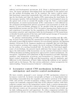
Fig. 1.13. Indoors rescue scenario: (a) Physical map; (b) Topological map
1 Multi-Robot Systems 29
Fig. 1.14. Navigation automata for the Crawler, Puller and Pusher robots (from
left to right)
One problem with such an approach is that the size of the finite state
automaton modelling an M-robots-N-sites scenario will grow quickly with
the number of robots and/or sites. Our results allow checking the blocking
and controllability properties of the (potentially large) automaton
modelling the multi-robot system with the blocking and controllability
properties of smaller automata, designated as navigation automata, which
model the navigation of each individual robot in the population. In
navigation automata for a given robot, each state corresponds to the site
where the robot is.
Due to the available space, we will only refer here the blocking result
for heterogeneous robots (homogeneous robots are a particular case with
specific results). For the controllability results and other details consult
[28].
Theorem: In a generic N-robots-M-sites system, for its modelling
automaton G to be non-blocking, all the navigation automata G
i
, i=1,…,N
must be non-blocking. Each G
i
is a marked automaton with a marked state
per site where there is at least one robot i in the target configuration.
Similarly, if G is blocking, there is at least one i and one marked state of G
i
such that G
i
is blocking.
One modelling example following this approach concerns a team of
three heterogeneous robots, with the following individual skills:
x the Crawler has tracker wheels and is capable of climbing and
descending stairs. It is able to open doors only by pushing;
x the Puller is a wheeled mobile manipulator, able to open doors either by
pushing or pulling. However, it is not able to climb stairs;
x the Pusher is a wheeled robot, able to open doors only by pushing. It
cannot climb stairs.
30 P.U. Lima and L.M. Custódio
The rescue operation takes place in the indoor environment depicted in
Fig. 1.13. (an indoor rescue scenario). Fig. 1.13.a) represents the physical
map, and Fig. 1.13.b) the corresponding topological map. Each of the
robots is described by a different navigation automaton, as represented in
Fig. 1.14. The robots will leave room 1 to assist three different victims,
somewhere in the building.
The doors open as shown in Fig. 1.13., thus limiting the robots access to
the different rooms. Inside rooms 6 or 7, only the Crawler can go upstairs.
In rooms 3 and 4, all the robots may fall downstairs, i.e., events Go(6) and
Go(7) are uncontrollable for all robots. Blocking and controllability results
concerning this result are presented in [27].
1.4.2 Formation Feasibility
Formation control is a relatively recent area of research, e.g., [8], where
many fundamental questions remain unanswered. The control of a
formation requires individual robots to satisfy their kinematics while
constantly satisfying inter-agent constraints. In typical leader-follower
formations, the leader has the responsibility of guiding the group, while the
followers have the responsibility of maintaining the inter-robot formation.
Distributing the group control tasks to individual robots must be
compatible with the control and sensing capabilities of the individual
robots. As the inter-robot dependencies get more complicated, a systematic
framework for controlling formations is vital.
In a joint work with the GRASP Lab, at the University of Pennsylvania,
we have proposed a framework to determine motion feasibility of
multi-robot formations [43]. Formations are modelled using formation
graphs, i.e., graphs whose nodes capture the individual robot kinematics,
and whose edges represent inter-robot constraints that must be satisfied.
We assume kinematic models for each robot, described by drift free
control systems. This class of systems is rich enough to capture holonomic,
nonholonomic, or underactuated vehicles.
Two distinct types of formations are considered: undirected formations
and directed formations. In undirected formations each robot is equally
responsible for maintaining the formation. For each formation constraint
between two robots, cooperation is assumed to satisfy the constraint.
Undirected formations therefore present a more centralized (in the sense of
the required information) approach to the formation control problem, as
communication between all the robots is, in general, necessary. In directed
formations, for each inter-robot constraint, only one of the robots (the
follower)
is responsible for maintaining the constraint. Directed formations,
1 Multi-Robot Systems 31
therefore, represent a more decentralized solution to the formation control
problem. Not only the required information flow is restricted to the pairs of
robots linked by an edge but also the synthesis of feedback control laws
enforcing the constraints is also simpler.
Two problems are tackled in this work, for which we just summarize the
main results here, as a detailed explanation would require a mathematical
background that is out of the context of this book:
x feasibility problem: given the kinematics of several robots along with
inter-robot constraints, determine whether there exist robot trajectories
that maintain those constrains. For both directed and undirected (not
necessarily rigid) formations we obtain algebraic conditions that
determine formation motion feasibility.
x When a formation has feasible motions, the formation control
abstraction problem is then considered: given a formation with
feasible motions, obtain a lower dimensional control system that
maintains formation along its trajectories. Such control system allows
controlling the formation as a single entity, therefore being well suited
for higher levels of control. The directions in which a feasible
formation can be controlled are determined, providing an abstraction
of the formation that can be controlled as a single entity.
1.4.3 Population Optimal Distribution Control
One of the most relevant (and hard) topics in MRS is the modelling of
large-size robot population behaviour. Under the current state-of-the-art, it
seems that results for small-sized populations do not scale necessarily well
for large-scale ones. Therefore, the mathematical modelling of large-size
agent populations should be useful to predict the evolution of a population
and subsequently design controllers or supervisors capable of changing the
population behaviour by the suitable adjustment of appropriate parameters.
One approach with large potential for this purpose is based on recent
results on the mathematical modelling of biological systems [33]. In fact,
our work in this direction has been originally developed for biological
experiments modelling, jointly with biologists [30].
The work concerns a large size population of robots that navigate in an
environment known with some associated uncertainty [29]. The motion of
the
robots in this environment is modelled by a stochastic hybrid automaton
with discrete states representing a set of motion commands (e.g.,
representing a set of directions that the robots should follow while
navigating),and acontinuous state space representing the robot motion state
(e.g., its posture and velocity). This hybrid automaton is stochastic because
32 P.U. Lima and L.M. Custódio
the transitions between discrete states are governed by transition
probabilities or, more precisely, under a Markov assumption, by transition
rates corresponding to the rates of exponential distributions that model the
times between events that cause the transitions. The transition rates
represent both the uncertainty about the environment, which causes the
robots to fail executing some commands (e.g., due to terrain irregularities
or lack of communication visibility), and the control signals (in the form of
control rates) that can modify that uncertainty, thus controlling the
population spatial distribution over time, as the robots move.
An important result of this work is the following
Theorem: The continuous time Markov Chain hybrid automaton end-
owed with one input (a stochastic event sequence) and having as output a
function of the continuous part of the state, with N discrete states and state
probability given by
)()( tPLtP
T
where
>@
)( )()(
1
tPtPtP
N
is
the probability of the discrete state and
>@
T
ij
L
O
is a transition
rate matrix and
ij
O
is the rate of transition from discrete state i to
discrete state j. The vector of probability density functions
>@
),( ),(),(
1
txtxtx
N
U
U
U
, where ),( tx
i
U
is the probability
density function of state (x,i) at time t, satisfies
»
»
»
¼
º
«
«
«
¬
ª
w
w
)),(),(.(
)),(),(.(
),(
),(
11
txtxf
txtxf
txL
t
tx
NN
T
U
U
U
U
#
(14)
where f(x,i) is the vector of vector field values at state (x,i).
If (x,i) represents the hybrid state of a large population of robots, the
result in this theorem can be used to predict the evolution of the probability
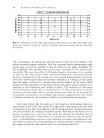
density function (pdf) of the population spatial distribution. Fig. 1.15.
represents a 2D example where a large number of land (e.g., rescue) robots
is left in a given region and are afterwards commanded by 3 aerial robots
which can order them to move in pre-defined directions. In the same
figure, the corresponding stochastic hybrid automaton modelling the
population spatial distribution over time is also represented. Using (14),
the predicted evolution of the population spatial distribution for a given set
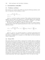
of transition rates and at several time instants is represented in Fig. 1.16.
by the contours of the pdfs for each discrete state and for the summation of
the discrete state pdfs.
1 Multi-Robot Systems 33
Fig. 1.15. On the left: (a) A robotic population controlled by three aerial robots
(sources) and (b) the vector fields created by control signal sources. On the right:
the stochastic hybrid automaton modelling the population spatial distribution over
time
Fig. 1.16. The pdf contours of the robot population states
i
(x,t), and the pdf of the
robots position K(x, t), for a given set of transition rates, given the model of Fig.
1.15. Plots shown at 6 time instants (from left to the right in the pictures), starting
at time t = 0. : is a region of interest for the mission
If a given region, such as the one denoted by : in Fig. 1.16., is of some
particular interest for our robotic mission and we want most of the robots
at time instant T in that region, an optimal control problem can be
formulated where the control signal u is a vector composed by the
transition rates between discrete states of the stochastic hybrid automaton
and the performance function to be maximized is given by
³
X
T
TxxwuJ ),()()(
U
34 P.U. Lima and L.M. Custódio
where the dependence in u comes from the dependence of
U
with the
transition rates, and w is a window function that spatially weights the state
pdf, e.g., to confine it to a sub-region : of the state space X.
The solution of this optimal control problem is not trivial, since (14) is a
partial differential equation. However, for certain cases, it is possible to
compute an open loop control solution. The derivation of such solution is
out of the scope of this book, but we provide an example for a
one-dimensional version of the problem depicted in Fig. 1.15., shown in
Fig. 1.17. Fig. 1.18. shows a pdf at time T = 3 h for this system very close
to the desired one. This resemblance depends in general of the control
amplitude, the system model and the time T.
Fig. 1.17. One-dimensional version of the robotic population example in Fig. 1.15.
In this example the robots can move left, right or stop
1.5 Cooperative Decision-Making
Previously in the chapter, we have already described solutions for MRS
architectures, cooperative perception and cooperative navigation. But to
act autonomously and machine-wise intelligently, a MRS team must be
able to plan action sequences and to take its own decisions autonomously.
1 Multi-Robot Systems 35
Fig. 1.18. Pdfs for discrete state 3 (stopped robots) concerning the example in Fig.
1.17., for k
1
= –0.5, k
2
= 0.25,
>@
)(00)(
3
xwxw
T
, u [0, 2], at several
time instants, including the terminal time T = 3 h
Of course, the decisions depend on the perception the robot has of its
surrounding environment, and most actions require navigating from one
point toanother
. The literatureis rich in planning solutions for single agents,
but multi-agent task planning, and especially multi-robot task planning are
relatively recent research subjects. Relevant issues for our group in this
research is the use of logic-based approaches to ensure the application of
36 P.U. Lima and L.M. Custódio
formal verification methods, the inclusion of uncertainty in the task, plan
and action models and the reduction of the search space whenever optimal
stochastic solutions are sought. Some of the work done in those directions
is described in the next sections.
1.5.1 Hybrid Logic-Based Decision System
The functional architecture described in Section 1.2 allows the
implementation of operators and the switching among them using different
approaches, as for example state machines or AI production systems.
Previous implementations of the PA machine were done using state
machines, which basically implemented a reactive decision-making
system, based on simple reactions to external or internal events. Robots
using this kind of decision mechanism usually show very primitive
behaviors, and are not able to accomplish non-trivial goals on complex,
dynamic, and incomplete domains. On the other side, deliberative
decision-making systems are able to make decisions based upon past
experience and by predicting future consequences of its actions. The
system may even act and decide in a way that was not predicted by the
designers, but that is actually valid and efficient in order to achieve the
goal. But deliberative systems are usually computationally heavy. A way
to take advantage of both kinds of systems is a hybrid decision-making
system with a reactive component and a deliberative component. The
system uses, normally, the decisions made by the former component. But,
when it takes too long to decide, it uses the decision made by the reactive
component.
So, in order to have a more abstract way to deal with decision-making
and behaviour switching, the PA machine has been implemented using a
distributed decision-making architecture supported on a logical approach
to modelling dynamical systems [37], based on situation calculus, which is
a second-order language specifically designed to representing dynamically
changing worlds. All the changes to the world are result of named actions.
A possible world history, which is simply a sequence of actions, is
represented by a first-order term called a situation. There is a distinguished
binary function symbol do; do(_, S) denotes the successor situation to S
resulting from performing the action _. For example, put(x, y) might stand
for the action of putting object x on object y, in which case do(put(A,B), S)
denotes the situation resulting from placing A on B when the current
situation is S. Notice that in situation calculus, actions are denoted by
function symbols, and situations (world histories) are first-order terms. For
example, do(score(A), do(takeBall(B), S
0
)) is a situation term denoting the
sequence of action [takeBall(B), score(A)].
1 Multi-Robot Systems 37
Generally, the values of relations and functions in a dynamic world will
vary from one situation to the next. Relations whose truth values vary from
situation to situation are called relational fluents and are denoted by
predicate symbols taking a situation term as their last argument. Actions
have preconditions, necessary and sufficient conditions that characterize
when the action is physically possible. World dynamics are specified by
effect axioms, which describe the effects of a given action on the fluents -
the causal laws of the domain. Axiomatizing a dynamic world requires
more than just action preconditions and effect axioms: frame axioms are
also necessary. These specify the action invariants of the domain, namely
those fluents that remain unaffected by a given action. But the problem
with frame axioms is that we can expect a vast number of them – the frame
problem: only relatively few actions will affect the truth value of a given
fluent; all other actions leave the fluent unchanged. This is problematic for
a theorem proving system, as it must efficiently reason in the presence of
so many frame axioms.
By appealing to earlier ideas of Haas, Schubert and Pednault, Reiter
proposed a quasi-solution to the frame problem, through a systematic
procedure for generating, from the effect axioms, all the frame axioms
needed.
The hybrid architecture developed for the high level decision-making of
our MRS comprises several components, from which the most important
ones are: World Representation, Reactive Component, Deliberative
Component and Behavior Selection, whereas the deliberative one uses the
procedure proposed by Reiter. Fig. 1.19. presents this architecture.
The World Representation Component (WRC) is responsible to build a
world model using sensorial data. From the sensory inputs and the static
information about the game, the WRC builds the game model, which
consists of basic information, like ball position and players’ postures, and
advanced information, such as cooperative decisions. The variables used to
define the world model are stored in a blackboard, as described in Section
1.2.
Based on this information a more pictorial world model is build, and
shared by all the robots. The idea is to focus the attention on the most
important moving element in the game, the ball. But to make adequate and
efficient decisions robots must see the world in a more abstract way. The
idea
is to divide the area surrounding the ball in six cones, and each cone in
three different zones (near, middle, far). Then we classify every element of
the game (opponents, teammates, goals, field lines, etc.) using this relative
positioning, and work with things like ”near goal”, ”has line of pass”, etc
This world model is inspired on an idea from the CMU (Carnegie Mellon
38 P.U. Lima and L.M. Custódio
University) simulation soccer team [42]. Fig. 1.20. graphically presents an
example of a possible world situation.
Fig. 1.19. Hybrid architecture
Fig. 1.20. World model
1 Multi-Robot Systems 39
The reactive component has two main purposes: to guarantee a quick,
real-time decision to be executed by the robot, and to react to unexpected
events. On the robotic soccer domain, such things may happen very often:
if a robot has the ball and plans to take it to the goal, and score, it needs to
react to an unexpected event (like an opposite robot taking the ball away
from it, the robot loosing the ball, or bumping against another robot). This
component, called Basic Logic Decision Unit (BLDU) and supported on
first-order logic statements, allows us to easily model the reactive
behaviour of the robot. The BLDU runs in a cyclic manner and, at each
iteration, it executes some operations related to the decision process and
the world modeling. First, it broadcasts the status of the robot to its
teammates. This includes the player role and the play mode (playing,
paused, going to start position, etc). Then, it checks if it needs or wants to
change its role. Finally, it decides the next behaviour to be executed (going
to some place on the field, taking the ball to goal, etc).
The reactive decision process is based on a set of Prolog rules,
constituted by a set of preconditions that must be all true in order for that
rule to be applied. The set of rules of the BLDU has a pre-defined order, in
the sense that the first rule following that order that has all pre-conditions
true will be the one used to make a decision. A pre-condition is anything
that can be represented by a logical formula, like having the ball, or being
inside a pre-determined area of the field. In Fig. 1.21. there are two
examples of rules used in BLDU. The first one is related with the defender
role. This rule tells the control component to move the robot to a specific
position on the field (given by X, Y, Theta) and it is applied if the robot is
playing, it sees the ball but does not have it, the ball is outside the
defenders zone, the robot is not near the position where he wants to go (a
simple hysteresis), and there is not another robot in that position. The
second rule is related to the attacker, and tells low-level control to score if
the robot is playing, if the ball is in the attacker zone, if the robot can see
the opposite goal, if it sees and have the ball, and if it is near the goal. This
way it is very easy to design new behaviors, simply by adding new rules to
the system. The designer just needs to be careful with the rules precedence.
This is clearly an easier system to work with, compared to the state
machine.
In order to compare the BLDU with the state machine implementation,
we performed the following test: the robot starts facing the opposite goal,
near the penalty mark. The robot must go back to the middle of the field,
get the ball, return to the opposite goal and score. We applied this test ten
times using each system (logic based decision system and the original
state-machine decision system). The results are on Fig. 1.22.
40 P.U. Lima and L.M. Custódio
Fig. 1.21. Two example rules of the Basic Logic Decision Unit
Not surprisingly the results obtained are similar for both systems, since
the low-level control unit is the same. For the robot performance on this
test, the control unit is much more important than which tool is used for
behavior switching. The logic-based system has showed to be fast enough
(even a little faster than the state machine) to handle the low-level control
problems, like behavior switching, with the right timings. So, we
concluded that the BLDU might replace the state machine without
negative consequences, and leave room for many improvements like the
one described next.
Fig. 1.22. Average results for the tests using both decision systems
One good example of the simplicity and power of the BLDU is the
management of player roles. We defined three roles for our players:
attacker, defender and full player. It would be very hard to
model all these behaviours using a state machine, but it would be even
harder to switch roles in real-time, like BLDU does. This dynamic role
switching is also an example of the kind of cooperation we intend to have
with our architecture. The robot keeps checking if it needs or wants to
switch roles. The need comes from two situations: if a robot stops playing
(for instance, due to a referee decision, or a software crash), or if another
robot decides to change its role. In the latter case, it may be necessary to
switch roles in order to keep the strategy of the team.
But when the robot decides it wants to change roles? Imagine a
defender in a situation that the ball enters the defensive midfield. It will
try to approach it, andtake it to the opponent goal
. But,tryingto score a goal
isanattacker’s task,and, moreover, it would leave the team with no one
1 Multi-Robot Systems 41
protecting the goal. So, one of the teammates will switch to defender
and go back in the field, protecting the goal again. The old defender
may become an attacker after a possible shot; it does not need to return
to its old position and lose time and battery power. Fig. 1.23. shows a
dynamic change: when the black robot (defender) catches the ball at the
defense, and takes it to the opponents’ goal, the gray robot (attacker)
switches to defender to replace his teammate.
Fig. 1.23. Dynamic role exchange
The Deliberative Component, called Advanced Logic Based Unit
(ALBU), is responsible to determine plans (sequences of behaviours) that
allow the team to achieve something (like scoring on the opposite goal).
The development of the ALBU has been made in GOLOG, a language
built on top of Prolog with the purpose of programming intelligent robot
behaviour.
This language allows us to use situation calculus in order to produce
plans. The language semantics is defined through a macro-expansion into
sentences of the situation calculus. GOLOG offers significant advantages
over current tools for applications in dynamic domains like the high level
programming of robots and software agents, process control, discrete event
simulation, complex database transactions, etc.
More importantly, GOLOG programs are evaluated with a theorem
prover. The user supplies precondition axioms, one per action, successor
state axioms, one per fluent, a specification of the initial situation of the
world, and a GOLOG program specifying the behavior of the agents in the
system. Executing a program amounts to finding a ground situation term V
such that:
Axioms |= Do(program, S
0
, V).
i.e., the fluent Do(program, S
0
, V) is derivable from the axioms.
This is done by trying to prove
42 P.U. Lima and L.M. Custódio
Axioms |= (
s
) Do(program, S
0
, s),
i.e., there exists a situation s such Do(program, S
0
, s) is true. If a
constructive proof is found, such a ground term do(a
n
, do(a
2
, do(a
1
, S
0
)) )
is obtained as binding for the variable s, where S
0
denotes the initial
situation. Then the sequence of actions [a
1
, a
2
, , a
n
] is sent to the primitive
action execution module.
Our objective was to develop a tool capable of planning and control task
execution in a distributed environment. To do so we assumed that: the
agents (robots) can generate, change and execute plans; a plan can be
generate, and executed by one or more agents; decisions over the
generated plans are based on hypotheses, i.e., assumptions over future
states that cannot be guaranteed; and the agents have the capacity to
communicate among them, and share information about plans or
environment states. Since the GOLOG programming logic is oriented to a
single agent we cannot apply it directly, rather we will have to be careful
with the task synchronization among plan tasks, among team members,
and take into account that our world model is based on sensors and
information shared among the team members, and does not change only as
result of our actions, since there are also other agents that can affect the
environment. This last problem will be addressed in future work, for now
when the environment is affected by an action on other agent in such a
way that makes the plan invalid, the agent has to generate a new plan.
The Behaviour Selection (BS) module chooses between the decisions
produced by Deliberative and Reactive components. It also handles plan
execution and checks if it is still valid. If a plan is no longer valid (due to
an action pre-condition being no longer true), it will discard the plan and
use the reactive decision. This way, the robot may actually react to an
unexpected event.
An example of a cooperative plan determined by the deliberative
component for a soccer game situation where we have two robots, both
starting at their mid-field, but the ball is near the opponent goal, is given
next.
The plan for robot 1, denoted “bp”, is:
[ actionPass(bp,ph),
actionWaitFor(bp,ph,actionGo2Goal(bp)),
actionWaitFor(bp,bp,actionGetClose2Ball(bp)),
actionGetClose2Ball(bp) ]
and the plan for robot 2, denoted “ph”, is:
[ actionScore(ph),
actionWaitFor(ph,ph,actionTakeBall2Goal(ph)),
1 Multi-Robot Systems 43
actionTakeBall2Goal(ph),
actionWaitFor(ph,ph,actionGo2Goal(ph)),
actionGo2Goal(ph),
actionHelp(ph,bp) ]
1.5.2 Distributed Planning and Coordinated Execution
The work described next was developed in the context of the RESCUE
project, which aims at the development of novel methodologies for using
robotic teams in rescue operations. Typically, a rescue operation within a
situation of catastrophe involves several and different rescue elements
(individuals and/or teams), none of which can effectively handle the rescue
situation by itself. Only the cooperative work among all those rescue
elements may solve it. Considering that most of the rescue operations
involve a certain level of risk for humans, depending on the type of
catastrophe and its extension, it is understandable why robotics can play a
major role in Search and Rescue situations (S&R), especially teams of
multiple heterogeneous robots.
The overall goal of the RESCUE project is to develop a robotic team,
constituted by more than one robot, capable of autonomously handle a
rescue operation. This project can be seen at different levels of abstraction,
such as a technological level (e.g., hardware development), a level of
control (e.g., motor control), a level of robot navigation, and a level of task
planning, if an individual robot is considered. If we assume also the
existence of a team of robots, new levels must be added, for instance a
level of robot cooperation and a level of mission management. At these
levels, the objectives are making robots cooperate to fulfill their common
goals, both through cooperative planning and cooperative execution.
This work is mainly focused on the problem of distributed planning and
task allocation in a multi-robot rescue system, assuming that teamwork
(i.e., cooperative tasks) plays an important role on the overall planning
system. However, all considerations, related with technology and
utilization of real robots, were not an issue in this work. So our rescue
team is composed of agents, virtual entities interacting within a simulated
environment and capable of some intelligent actions, both individual and
cooperative.
For that, an agent architecture has been developed, inspired on a
Belief-Desire-Intention (BDI) architecture, considering that each agent
interacts with others in the same rescue scenario, with the same interface
and
ontology
. Moreover, the proposed architecture takes into account issues
as agent heterogeneity, failures recover, cooperation, to name but a few.
Besides that, agents equipped with this architecture are prepared to act in a
44 P.U. Lima and L.M. Custódio
non deterministic environment (where its state could change without any
agent action), incomplete (meaning that only information agents have is
acquired by their sensors which provided only incomplete data about the
environment state), dynamic (meaning that planning decisions made for a
certain environment state could be invalid when they are executed,
claiming for some re-planning).
Since teamwork is a key aspect of this work, agents need to negotiate
the execution of certain actions, either because an agent does not have the
right skills to do it, or it evaluates that another agent could do it better
(with a lower cost). To implement this, a Contract-Net system was
developed and integrated in the agent architecture. This system allows
agents to propose and negotiate contracts with other agents, and gives the
necessary guarantees for maintaining “signed” contracts consistency (i.e.,
if an agent cannot fulfill a contract it must inform others involved in that
contract).
The main decision process, the planner, was implemented based on a
Hierarchical Decomposition Partial Order Planner (HDPOP) approach,
with an important extension, the possibility to handle (plan) the resources
needed for each of the tasks. The planner was developed using the STRIPS
language and is supported on a variation of the well-known A* search
algorithm, the Iterative Deepening A* (IDA*).
To experiment and evaluate the proposed planning system, a simplified
version of a rescue simulator was also developed. This simulator allows
creating virtual rescue scenarios where rescue teams should face building
and forest fires, civilians trapped in collapsed buildings, and roads
blocked. The rescue teams are composed of aerial and land robots, with
different skills. The former could perform a survey of the affected region
and are also capable of transporting victims to rescue spots. The latter may
be a civil protection (CV) agent (responsible for organizing the rescue
missions and contracting other agents), physician agent (capable of giving
first aid assistance), firefighters or an agent capable of removing
roadblocks.
1 Multi-Robot Systems 45
Stretcher
First Aid Packa
g
e
Victim
Fl
y
in
g
A
g
ent
Ph
y
sician A
g
ent
Civil Protection
Agent
Water
Fig. 1.24. A simulation scenario with three agents: a civil protection agent, a
physician agent and a flying agent. There are also a first aid package and stretcher
needed to rescue the victim
Fig. 1.24. presents a simulated rescue scenario where three agents have
to cooperate to search and rescue a victim. After the victim being found,
the CV agent generates a plan to rescue it, which includes contracting the
physician agent, finding and getting the stretcher, putting the victim on it,
and contracting the flying agent to transport the victim to a rescue spot.
The physician agent makes a plan to get the first aid package, go near to
and help the victim, and the flying agent generates a transport plan.
Fig. 1.25. shows the state of the three agents immediately after the
victim has been found by the flying agent.
In general, the results obtained show that a distributed approach to a
rescue problem is clearly an interesting solution when compared with a
centralized one. One might lose some quality of the planning solutions, but
gains more flexibility, redundancy and the possibility of parallelizing the
planning process. One key word emerging from this work and its results
was “delegation”, meaning that agents should delegate as much as possible
given other agents skills, particularly whenever planning is concerned.
46 P.U. Lima and L.M. Custódio
0 CtrFirstAid(victim1)
0 Go(Here, Stretcher)
1 Grab(Stretcher)
2 Go(Stretcher, Victim1)
3 PutStretcher(Victim1)
4 CtrTransport(Victim1)
5 Finish()
0 AirRecon(HERE)
1 Finish()
0 Go(Here, FirstAid)
1 Grab(FirstAid)
2 Go(FirstAid, Victim1)
3 Aid(Victim1)
4 Finish()
Fig. 1.25. The state of the three agents immediately after the victim has been
found by the flying agent (on the right is shown the current plan of each agent).
Ag. 1 is the civil protection agent; ag. 2 is the flying agent and ag. 3 is the
physician agent. The green areas represent the regions already explored by each
agent; the red lines in the plans indicate the action(s) under execution
1.5.3 Relational Behaviours in Cooperative MRS
Our research on relational behaviours has been mainly driven by the
application to soccer robots, but the motivation comes from the need to
design, implement and test in real robots concepts from teamwork theory,
originally developed for multi-agent systems.
One cooperation mechanism that we first implemented in 2000 consists
of avoiding that two or more robots from the same team attempt to get the
ball. A relational operator was developed to determine which robot should
go to the ball and which one(s) should not. In the current implementation,
1 Multi-Robot Systems 47
each robot that sees the ball and wants to go for it uses a heuristic function
to determine a fitness value. This heuristic penalizes robots that are far
from the ball, are between the ball and the opposite goal and need to
perform an angular correction to centre the ball with its kicking device.
Each robot broadcasts its own heuristic value, and the robot with the
smallest value is allowed to go for the ball, whereas the others execute a
Standby behaviour. Another example of utilization of this mechanism is
the decision to dynamically switch roles among players, e.g., the
defender becomes an attacker when it acquires the right to get the
ball, and correspondingly the attacker becomes a defender.
A relational behaviour is not seen in our research as a simple matter of
relating the tasks performed by two or more robots from the team. We
support relational behaviours on teamwork theory techniques, such as the
Joint Commitment Theory (JCT) [7]. One such example is the
implementation of a ball pass between two robots [46]. These behaviours
have a general formulation based on the JCT and use the individual robot
navigation methods. The robots are capable of committing to relational
pass behaviour where one of the robots is the kicker and the other the
receiver. If any of the robots ends the commitment, the other switches to
an individual behaviour.
In Fig. 1.26., several individual behaviours can be found within the
commitment. At any time the participants have to select the correct
behaviour individually. Commitments among teammates are established at
the relational behaviour level of the architecture described in Section 1.2.
Behaviour selection is done in the logic machine module of the hybrid
logic-based decision system explained in sub-section 1.5.1. The robot first
chooses a role, next it selects a commitment, and finally the individual
behaviour.
Predefined logical conditions can establish a commitment between two
robots. Once a robot is committed to a relational behaviour, it will pursue
this task until one or more conditions become false, or until the goal has
been accomplished. The initiative for a relational behaviour is taken by
one of the robots, which sets a request for a relational behaviour. A
potential partner checks if the conditions to accept the request are valid. If
so, the commitment is established. During the execution of the
commitment the changing environment can lead to failure or success at
any time. In that case the commitment will be ended.
In general, within a commitment three phases can be distinguished:
Setup, Loop and End. During the set up and ending of a commitment, a
robot is not executing a relational behaviour. The logic machine will not
select any relational behaviour, and no commitment takes place during the