Innovations in Robot Mobility and Control - Srikanta Patnaik et al (Eds) Part 6 ppt
Bạn đang xem bản rút gọn của tài liệu. Xem và tải ngay bản đầy đủ của tài liệu tại đây (718.14 KB, 20 trang )
88 Q.V. Do et al.
2.4.3 Landmark Recognitions
In autonomous robot navigations, it is critical that the vision system is able
to achieve reliable and robust visual landmark recognitions in real-time.
Fault landmark recognitions will lead to ‘the robot is lost’ situation, where
the robot loses its perception and its current location in the environment. In
general, fault recognitions are cased by image distortions. Therefore, the
challenge is to develop techniques to overcome image distortions due to
noises introduced through wireless video links. Furthermore, as the robot
navigates the size and shape of landmark are changing constantly. These
changes are directly proportional to the robot’s speed and the robot’s ap-
proaching angles with respect to the target landmark during navigation.
The following sections describe techniques used to overcome image distor-
tions, and changes in landmark’s size and shape.
2.4.3.1 Distortion Invariant Landmark Recognition
The SVALR architecture recognises landmarks based on their shapes.
Therefore if the shape of a landmark is affected by noises causing image
distortions, changing the size and shape of the landmark will result in a
recognition failure. The architecture employs two concepts named band
transformation and shape attraction to overcome image distortions and
small change in the landmark’s size and shape.
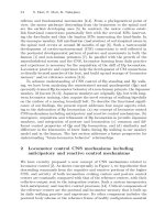
The central idea to band transformations is to thicken the shape of the
landmark by means of a Gaussian filter [56] or an averaging mask [57] us-
ing eq.2.6. This will produce a blurred edge image. The blurred image is
then subjected to a shape attraction process. The shape attraction process
uses the memory template to selectively attract the corresponding edge ac-
tivities in the blurred shape and project them into the original undistorted
shape. The concept of shape attraction is further illustrated in Fig. 2.13.
)*/(),(),(
5
0
5
0
crcjriIjiIB
r
r
c
c
»
¼
º
«
¬
ª
¦¦
(2.6)
Where IB is the burred image, r & c are the size of the averaging window
and I is the input edge image.
2.4.3.2 Sizes and Views Invariant Landmark Recognition
The SVALR architecture requires the recognition of landmarks that are
continuously changing in size and shape during navigation. This leads to
the development of a simultaneously multiple-memory image search
(SMIS) mechanism. This mechanism is capable of providing real-time size
2 Vision-Based Autonomous Robot Navigation 89
and view invariant visual landmark recognition [58]. The central idea to
the SMIS mechanism is to pre-store multiple memory images of different
landmark’s sizes and from different views and compares each input image
with multiple memory templates.
Fig. 2.13. The shape attraction process
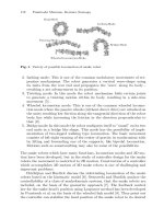
Through experiment it was found that the landmark’s size is directly
proportional to the distance between the landmark and the robot. As a re-
sult, the shape attraction method is capable of providing a small detectable
region for each memory image stored in memory as illustrated in Fig.
2.14(a). The first memory image is taken from a distant, K
1
, away from the
landmark. This provides a detectable region around the location, X
1,
and a
detectable angle, D. Thus, multiple memory images can be selected with
adjacent detectable regions joined together to provide landmark recogni-
tion over larger distances and hence larger changes in landmark’s size.
Therefore, by storing multiple memory images of different landmark’s
sizes, with detectable regions joined together will provide the system with
full size invariant landmark recognitions. The numbers of memory images
required depend on the rate of change in the landmark’s size, which is di-
rectly proportional to the robot’s speed.
Similarly, each memory image provides a detection angle, D. Therefore,
multiple views covering 360
0
around the landmark with the angle between
these views equal to D are stored for each landmark to provide full view
invariant landmark recognitions as shown in Fig. 2.14(b). The number of
views required to cover 360
0
are given by the eq.2.7.
Band Transformation
Stage
Shape Attraction
Stage
90 Q.V. Do et al.
No. of views = 3600/ (2.7)
Fig. 2.14. The SMIS mechanism for achieving size and view invariant landmark
recognitions. (a) Size invariant landmark recognition using two memory images.
(b) View invariant landmark recognition using views memory images
The central idea of the SMIS mechanism is to search for multiple mem-
ory images simultaneously. Thus, it allows the SVALR architecture to rec-
ognise landmarks of different sizes and from different views. However, the
SMIS mechanism is very computational intensive as many views are
evaluated simultaneously. Therefore the SMIS mechanism employs a view
selector to select a limited number of views to use in the searching process
for reducing the computational requirement. The view selector determines
appropriate views based on the robot’s heading, which is provided by the
magnetic compass on-board the robot via wireless data link, illustrated on
the top in Fig. 2.14(b). This reduces to only the current view and two left-
right adjacent views are activated instead of simultaneously searching
through all the views associated with a landmark.
Landmark Templates stored in memory
M2
M1
w
Į
K
1
Detectable Region M1
Detectable Region M2
H
1
H
T
X
1
X
2
Robot’s
Headings
View
Selector
Selected
Views
h
1
(a)
(b)
2 Vision-Based Autonomous Robot Navigation 91
2.4.3.3 Light Invariant Recognition
The SVALR architecture processes input images based on pre-processed
edges or boundary information of an edge detection stage. Therefore, the
efficiency of the architecture is directly depending on the quality of edge
information obtained. Common edge detection methods such as Sobel,
Prewitt and Robinson edge detections, all detecting edges based on the dif-
ferences between the sums of pixels values on the left and right regions of
a target pixel. This is generally achieved by applying an appropriate edge
detection convolution mask. The strength of the detected edges using these
methods is directly affected by the amount of light in the environment.
Changes in light intensity have an immediate impact on the strength of
edges obtained at the edge detection stage. This section describes a new
method for edge detection named contrast-based edge detection. This edge
detection method enables the SVALR architecture to recognise landmarks
under different lighting conditions.
The contrast-based edge detection is developed based on Grossberg’s
theory on shunting-competitive neural networks [59, 60]. The equation for
dynamics competition of biological neurons is given in eq.2.8. Where A
is the rate of decay, B and D are some constant that specify the range of
neurons activities. E
ij
and C
ij
are excitatory and inhibitory inputs respec-
tively.
ijijijijij
ij
CDxExBAx
dt
dx
)()(
(2.8)
At equilibrium
0
dt
dx
ij
, there exists a steady state solution for the
neuron,
ij
x given in eq.2.9.
0)()(
ijijijijij
EDxCxBAx
(2.9)
ijij
ijij
ij
ECA
DEBC
x
(2.10)
In order to design the contrast-based edge detection, the C
ij
and E
ij
terms are replaced with the left and right columns of an edge detection
mask instead of the excitatory and inhibitory inputs in dynamic competi-
tive neurons as shown in Fig. 2.15. Since B and D are constants. Let B &
92 Q.V. Do et al.
D =1, this gives the contrast-based edge detection equation as shown in
eq.2.11.
¦¦
¦¦
||||
||||
ijijijij
ijijijij
ij
ICIEA
IEIC
x
(2.11)
Where A is a small constant preventing the equation from dividing by zero
and I
ij
is the input gray level image. Notice that both Sobel and Robinson
edge detection masks can be used in the contrast-based edge detection.
In general, the contrast-based edge detection uses a conventional edge
detection convolution mask for detecting the difference between
neighbouring left and right regions of a target pixel. The calculated differ-
ence is divided by the total sum of all edge activities from both left and
right regions within the edge detection mask
Fig. 2.15. Contrast-based vertical edge detection masks
2.4.3.4 Final SVALR Architecture
The final SVALR architecture is illustrated in Fig. 2.16. Initially, a gray
level image is pre-processed using the contrast-based edge detection to
generate an edge image. This image is blurred using a 5x5-averaging win-
dow for achieving distortion and small size and view invariant landmark
recognitions using shape attraction. A window-based searching mechanism
2 Vision-Based Autonomous Robot Navigation 93
is employed to search the entire input blurred image for a target landmark.
The search window is sized, 50x50 pixels, each region within the search
window is processed in the pre-attentive stage using both the ROI and the
signature thresholds as illustrated at the bottom of Fig 2.16. The selected
regions are passed into the attentive stage, where they are modulated by
the memory feedback modulation given in eq.2.5. Then, lateral competi-
tion between pixels within the selected region is achieved by applying L2
normalisation. This results in a filter effect, which enhances common edge
activities and suppresses un-aligned features between the memory image
and the input region achieving object background separation.
The SMIS mechanism selects appropriate views based on the robot’s
heading as illustrated on the top of Fig. 2.16. It is found that the SVALR
architecture requires a minimum of two memory images for each view and
eight views to achieve size and view invariant landmark recognition re-
spectively. This is achieved at a moderate robot’s speed. The selected
memory images are used to compare with the selected input region. The
matching between selected input regions and corresponding memory im-
ages are determined based on two criteria.
Firstly, each selected input region is compared with two selected mem-
ory images (belonging to one view) separately using the cosine between
two 2-D arrays. The cosine comparison results with a match value range
from 0 to 1, where 1 is the 100% match, which is evaluated against a
match-threshold of 90% match. If either results are greater than the match
threshold, then the second criterion is evaluated. The second criterion is
based on a concept of top-down expectancy from physiological study.
Based on a given map, the landmark is expected to appear at a certain dis-
tance and direction. These two constraints are used to further enhance the
robustness of the landmark recognition stage. Therefore, a match only oc-
curs when the robot has travelled a minimum required distance and head-
ing in the approximate expected direction.
2.5 Results
The autonomous mobile robot is evaluated in indoor laboratory environ-
ment. The robot is provided with a topological map, which consists of the
relative directions and approximate distances between objects placed on
the laboratory floor. A number of autonomous navigation trials were con-
ducted to evaluate the SVALR architecture ability to recognise landmarks
in clean, cluttered complex backgrounds and under different lighting con-
ditions. Four trials were selected for discussion in this chapter.
94 Q.V. Do et al.
Fig. 2.16. The Selective Visual Attention Landmark Recognition Architecture
In the first trial, objects that are chosen to serve as landmarks were
placed in front of clean backgrounds and critical points where the robot
needs to make a turn. During navigation each input images is pre- proc-
essed by the contrast-based edge detection and then blurred using a 5x5
averaging window for achieving distortion invariant landmark recognition
as shown in Fig. 2.17(b) and Fig. 2.17(c) respectively. The landmark
search and recognition is performed on the blurred image, where each
50x50 region is compared with the memory image. The results are
Signature
Threshold
Less than
threshold
COMPARE
ROI
Threshold
COMPARE
Match Threshold
COMPARE
N
ormalised
Input Region
Gray Level
Images
Memory
Feedbac
k
Modulation
Selected Regions
COMPARE
Memory
Images
Send to Robot
Reset
Contrast-Based
Edge Image
Blurred Image
View Selector
Topological Map
Top-Down
Expectancy
Heading
Pre-attentive Stage
Attentive Stage
SMIS
Mechanism
2 Vision-Based Autonomous Robot Navigation 95
converted into a range from 0-255 and displayed as an image form in Fig.
2.17(d). The region with highest intensity represents the highest match
with the memory image. The dot indicated by an arrow at the bottom cen-
tre of Fig. 2.17(d) highlights location of maximum match value and is
greater than the match threshold (location where the object is found). This
location is sent to the robot via wireless data link. The navigational algo-
rithm on-board the robot based on the provided map to perform self-
localisation and more toward the next visual landmark. In this trial, the re-
sults show that the SVALR architecture is capable of recognising all visual
landmarks in clean backgrounds, successfully performing self-localisation
and autonomous navigation. Finally, black regions in Fig. 2.17(d) are ones
that have been skipped by the pre-attentive stage. This has increased the
landmark searching process significantly [55].
In the second trial each landmark is placed in front of a complex back-
ground with many other objects behind it. This is to demonstrate the
SVALR architecture ability to recognise landmarks in cluttered back-
grounds. Similarly, incoming images are processed as discussed previously
with the landmark recognition results illustrated in Fig. 2.18, which shows
a sample processed frame during navigation. The dot indicated by the ar-
row highlights the location where the landmark was found in Fig. 2.18(d).
The robot is able to traverse the specified route, detecting all visual land-
marks embedded in complex backgrounds.
In the third trial, the same experimental setup as trial two was used ex-
cept all the lights in the laboratory were turned off with windows remain
open to simulate sudden change in image conditions. All landmarks are
placed in complex cluttered backgrounds. A sample processed frame dur-
ing the navigation is illustrated in Fig. 2.19. Similarly, the system is able to
successfully traverse the route, recognising all landmarks under insuffi-
cient light conditions and embedded in cluttered backgrounds.
2.6 Conclusion
This chapter has provided an insight into autonomous vision-based
autonomous robot navigations, focusing on monocular vision and naviga-
tion by 2D landmark recognitions in clean and cluttered backgrounds as
well as under different lighting conditions. The essential components of
monocular vision systems are described in details including; maps, data
acquisition, feature extraction, landmark recognition and self-localisation.
Then a 2-D landmark recognition architecture named selective visual
attention landmark recognition (SVALR) is proposed based on a detailed
96 Q.V. Do et al.
analysis of how the Adaptive Resonance Theory (ART) model may be ex-
tended to provide a real-time neural network that has more powerful atten-
tional mechanisms. This leads to the development of the Selective Atten-
tion Adaptive Resonance Theory (SAART) neural network. It uses the
established memory to selectively bias the competitive processing at the
input to enable landmark recognitions in cluttered backgrounds. Due to the
dynamic nature of SAART, it is very computationally intensive. Therefore
the main concept in the SAART network (top down presynatic facilitation)
is re-engineered and is named memory feedback modulation (MFM)
mechanism. Using the MFM mechanism and in combination with standard
image processing architecture leading to the development of the SVALR
architecture.
A robot platform is developed to demonstrate the SVALR architecture
applicability in autonomous vision-based robot applications. A SMIS
mechanism was added to the SVALR architecture to cope with image dis-
tortions due to wireless video links and the dynamic changing in land-
mark’s size and shape. The SMIS mechanism uses the concepts of band
transformations and the shape attraction to achieve image distortions, small
size and view invariant landmark recognitions. The experiments show that
the SVALR architecture is capable of autonomously navigating the labora-
tory environment, using the recognition of visual landmarks and a topo-
logical map to perform self-localisation. The SVALR architecture is capa-
ble of achieving real-time 2-D landmark recognitions in both clean and
complex cluttered backgrounds as well as under different lighting condi-
tions.
The SVALR architecture performance is based on the assumptions that
all visual landmarks are not occluded and only one landmark is searched
for and recognised at a time. Thus the problems of partial and multiple
landmarks recognitions haven’t been addressed. Furthermore, the robot
platform is designed and implemented with the primary purpose of validat-
ing the SVALR architecture and therefore omitting the obstacle avoidance
capability. In addition, the memory used in the SVALR architecture is pre-
selected prior to navigation and cannot be changed dynamically. This give
rises to a need for developing an obstacle avoidance capability and an
adaptive mechanism to provide some means of learning to the SVALR ar-
chitecture to cope with real-life situations, where landmarks move or
change its shape and orientations dynamically. These problems are re-
mained as future research.
2 Vision-Based Autonomous Robot Navigation 97
Fig. 2.17. A processed frame from the first trial, encountered in the navigational
phase. (a) Grey level image, (b) Sobel edge image, (c) Blurred image using a 5x5-
averaging mask and (d) The degree of match of the input image with the memory
image at each location
Fig. 2.18. A processed frame from the laboratory environment, encountered in the
navigational phase. (a) Grey level image, (b) Sobel edge image, (c) Blurred image
using a 5x5-averaging mask and (d) The degree of match of the input image with
the memory image at each location
(a) (b)
(c)
(d)
Match Location
(a)
(b)
(c)
(d)
Match Location
98 Q.V. Do et al.
Fig. 2.19. A sample processed frame during the second trial with all light turned
off, with minimal light enters from the laboratory windows. (a) Gray level input
image, (b) contrast-based edge detection, (c) Blurred image, (d) degree of
matches, converted into image scale and (e) Memory image and BMF filter, top
and bottom respectively
Acknowledgements
We would like to thank the Australian Defence Science and Technology
Organisation (DSTO) for supporting this research (contract No. 4500 177
390). Furthermore, we sincerely appreciate the technical assistance from
Patrick O'Sullivan and Tony Gelonese in the School of Electrical and In-
formation Engineering, University of South Australia, and Paul Munger
and Adrian Coulter of DSTO.
References
1. P. J. M
c
Kerrow, "Where are all the Mobile Robots?," in Studies in Fuzziness
and Soft Computing, Applied Intelligent Systems, J. Fulcher and J. LAckhmi C,
Eds.: Springer, 2004, pp. 179-200.
2. B. K. Muirhead, "Mars Pathfinder flight system integration and test," in Proc.
The IEEE Conference on Aerospace, pp.191-205, 1997.
(a) (b)
(c) (d) (e)
Match
Location
2 Vision-Based Autonomous Robot Navigation 99
3. L. Pedersen, M. Bualat, C. Kunz, S. Lee, R. Sargent, R. Washington, and A.
Wright, "Instrument deployment for Mars Rovers," in Proc. IEEE Interna-
tional Conference on Robotics and Automation, Proceedings. ICRA '03,
pp.2535 - 2542, 2003.
4. N. Winters, J. Gaspar, G. Lacey, and J. Santos-Victor, "Omni-directional vision
for robot navigation," in Proc. IEEE Workshop on Omnidirectional Vision,
pp.21-28, 2000.
5. R. Ghurchian, T. Takahashi, Z. D. Wang, and E. Nakano, "On robot self-
navigation in outdoor environments by color image processing," in Proc. The
7th International Conference on Control, Automation, Robotics and Vision,
ICARCV'02., pp.625-630, 2002.
6. D. Murray and C. Jennings, "Stereo vision based mapping and navigation for
mobile robots," in Proc. IEEE International Conference on Robotics and
Automation, pp.1694-1699, 1997.
7. M. Xie, C. M. Lee, Z. Q. Li, and S. D. Ma, "Depth assessment by using quali-
tative stereo-vision," in Proc. IEEE International Conference on Intelligent
Processing Systems, ICIPS '97, pp.1446-1449, 1997.
8. G. N. DeSouza and A. C. Kak, "Vision for Mobile Robot Navigation: A Sur-
vey," IEEE Transactions on Pattern Analysis and Machine Interlligence, vol.
vol.24, pp. 237-267, 2002.
9. D. Kortenkamp and T. Weymouth, "Topological Mapping for Mobile Robots
Using a combination of Sonar and Vision Sensing," in Proc. Proc. 12th Nat'l
Conf. Artificial Intelligence,, pp.979-984, 1995.
10. X. Lebegue and J. K. Aggarwal, "Automatic creation of architectural CAD
models," in Proc. The 1994 Second CAD-Based Vision Workshop, pp.82-89,
1994.
11. X. Lebegue and J. K. Aggarwal, "Generation of architectural CAD models us-
ing a mobile robot," in Proc. IEEE International Conference on Robotics and
Automation, pp.711-717, 1994.
12. V. Egido, R. Barber, M. J. L. Boada, and M. A. Salichs, "Self-generation by a
mobile robot of topological maps of corridors," in Proc. The IEEE Interna-
tional Conference on Robotics and Automation, Proceedings. ICRA '02.,
pp.2662 -2667, 2002.
13. T. Duckett and U. Nehmzow, "Exploration of unknown environments using a
compass, topological map and neural network," in Proc. IEEE International
Symposium on Computational Intelligence in Robotics and Automation,
pp.312-317, 1999.
14. X. Lebegue and J. K. Aggarwal, "Significant line segments for an indoor mo-
bile robot," IEEE Transactions on Robotics and Automation, vol. 9, pp. 801-
815, 1993.
15. H. P. Moravec and A. Elfes, "High Resolution Maps from Wide Angle sonar,"
in Proc. Proc. IEEE Int'l conf. Intelligent Robotics and Automation, pp.116-
121, 1985.
100 Q.V. Do et al.
16. J. Borenstein and Y. Koren, "Real-time obstacle avoidance for fact mobile ro-
bots," in Proc. IEEE Transactions on Systems, Man and Cybernetics, pp.1179 -
1187, 1989.
17. J. Borenstein and Y. Koren, "High-speed obstacle avoidance for mobile ro-
bots," in Proc. Intelligent Control, 1988. Proceedings., IEEE International
Symposium on, pp.382 -384, 1988.
18. A. Bandera, C. Urdiales, and F. Sandoval, "An hierarchical approach to grid-
based and topological maps integration for autonomous indoor navigation," in
Proc. The IEEE/RSJ International Conference on Intelligent Robots and Sys-
tems, pp.883-888, 2001.
19. D. Jung and A. Zelinsky, "Integrating spatial and topological navigation in a
behaviour-based multi-robot application," in Proc. IEEE/RSJ International
Conference on Intelligent Robots and Systems, IROS '99, pp.323 -328, 1999.
20. M. Tomono and S. Yuta, "Mobile robot localization based on an inaccurate
map," in Proc. IEEE/RSJ International Conference on Intelligent Robots and
Systems, pp.399 -404, 2001.
21. M. Tomono and S. Yuta, "Indoor Navigation Based on an Inaccurate Map Us-
ing Object Recognition," in Proc. IEEE/RSJ International Conference on Intel-
ligent Robots and Systems, pp.619 - 624, 2002.
22. M. Tomono and S. Yuta, "Mobile robot navigation in indoor environments us-
ing object and character recognition," in Proc. ICRA '00. IEEE International
Conference on Robotics and Automation, pp.313 -320, 2000.
23. A. Murarka and B. Kuipers, "Using CAD drawings for robot navigation," in
Proc. IEEE International Conference on Systems, Man, and Cybernetics,
pp.678-683, 2001.
24. G. Cheng and A. Zelinsky, "Real-time visual behaviours for navigating a mo-
bile robot," in Proc. The International Conference on Intelligent Robots and
Systems, IROS 96, pp.973-980, 1996.
25. Y. Matsumoto, M. Inaba, and H. Inoue, "Visual navigation using view-
sequenced route representation," in Proc. Robotics and Automation, 1996. Pro-
ceedings., 1996 IEEE International Conference on, pp.83-88, 1996.
26. G. Cheng and A. Zelinsky, "Real-time visual behaviours for navigating a mo-
bile robot," in Proc. Intelligent Robots and Systems '96, IROS 96, Proceedings
of the 1996 IEEE/RSJ International Conference on, pp.973-980, 1996.
27. R. C. Luo, H. Potlapalli, and D. W. Hislop, "Neural network based landmark
recognition for robot navigation," in Proc. The 1992 International Conference
on Industrial Electronics, Control, Instrumentation, and Automation, pp.1084 -
1088, 1992.
28. H. Li and S. X. Yang, "Ultrasonic sensor based fuzzy obstacle avoidance be-
haviors," in Proc. IEEE International Conference on Systems, Man and Cyber-
netics, pp.644-649, 2002.
29. E. Krotkov, "Mobile robot localization using a single image," in Proc. IEEE In-
ternational Conference on Robotics and Automation, pp.978-983, 1989.
30. Y. Watanabe and S. Yuta, "Position estimation of mobile robots with internal
and external sensors using uncertainty evolution technique," in Proc. The
2 Vision-Based Autonomous Robot Navigation 101
International IEEE Conference on Robotics and Automation, pp.2011-2016,
1990.
31. H J. von der Hardt, D. Wolf, and R. Husson, "The dead reckoning localization
system of the wheeled mobile robot ROMANE," in Proc. Multisensor Fusion
and Integration for Intelligent Systems, 1996. IEEE/SICE/RSJ International
Conference on, pp.603-610, 1996.
32. C C. Tsai, "A localization system of a mobile robot by fusing dead-reckoning
and ultrasonic measurements," in Proc. Instrumentation and Measurement
Technology Conference, 1998. IMTC/98. Conference Proceedings. IEEE,
pp.144-149, 1998.
33. H. Makela and K. Koskinen, "Navigation of outdoor mobile robots using dead
reckoning and visually detected landmarks," in Proc. Advanced Robotics, 1991.
'Robots in Unstructured Environments', 91 ICAR., Fifth International Confer-
ence on, pp.1051-1056, 1991.
34. J. Moran and R. Desimone, "Selective attention gates visual processing in the
extrastriate cortex," Science, vol. 229, pp. 782-784, 1985.
35. B. C. Motter, "Focal attention produces spatially selective processing in vis-
ual cortical areas V1, V2, and V4 in the presence of competing stimuli," Jour-
nal of Neurophysiology, vol. 70, pp. 909-919, 1993.
36. L. Chelazzi, E. K. Miller, J. Duncan, and R. Desimone, "neural basis for visual
search in inferior temporal cortex," Nature, vol. 363, pp. 345-347, 1993.
37. R. Desimone, M. Wessinger, L. Thomas, and W. Schneider, "Attentional con-
trol of visual perception: Cortical, and subcortical mechanisms," Cold Spring
Harbour Symposium in Quantitative Biology, vol. 55, pp. 963-971, 1990.
38. R. Desimone and J. Duncan, "Neural Mechanisms of selective visual atten-
tion," Annual Review of Neuroscience, vol. 18, pp. 193-222, 1995.
39. R. Desimone, "Neural mechanisms for visual memory an their role in atten-
tion," in Proc. Proceedings of the National Academy of Sciences, USA,
pp.13494-13499, 1996.
40. P. Lozo, "Selective attention adaptive resonance theory (SAART) neural net-
work for neuro-engineering of robust ATR systems," in Proc. IEEE Interna-
tional Conference on Neural Networks, pp.2461-2466, 1995.
41. P. Lozo. 1997, Neural theory and model of selective visual attention and 2D
shape recognition in visual clutter, PhD Thesis, Department of Electrical and
Electronic Engineering. Adelaide, University of Adelaide
42. S. Grossberg, "Adaptive pattern classification and universal recoding, II: Feed-
back, expectation, olfaction, and illusions," Biological Cybernetics, vol. 23, pp.
187-202, 1976.
43. S. Grossberg, "How does a brain build a cognitive code?," Psychological Re-
view, vol. 87, pp. 1-51, 1980.
44. G. A. Carpenter and S. Grossberg, "A massively parallel architecture for a self-
organizing neural pattern recognition machine," Computer Vision, Graphics,
and Image Processing, vol. 37, pp. 54-115, 1987.
102 Q.V. Do et al.
45. G. A. Carpenter and S. Grossberg, "ART 2: Self-organization of stable category
recognition codes for analog input patterns.," Applied Optics, vol. 26, pp.
4919-4930, 1987.
46. G. A. Carpenter and S. Grossberg, "ART 3: Hierarchical search using chemical
transmitters in self-organising pattern recognition architectures.," Neural Net-
works, vol. 3, pp. 129-152, 1990.
47. S. Grossberg, "Neural expectation: Cerebellar and retinal analogs of cells fired
by learnable or unlearned pattern classes," Kybernetik, vol. 10, pp. 49-57, 1972.
48. G. A. Carpenter, S. Grossberg, and J. Reynolds, "ARTMAP: a self-organizing
neural network architecture for fast supervised learning and pattern recogni-
tion," in Proc. International Joint Conference on Neural Networks, IJCNN-91-
Seattle, pp.863-868, 1991.
49. G. A. Carpenter, S. Grossberg, and J. H. Reynolds, "ARTMAP: Supervised
real-time learning and classification of nonstationary data by a self-
organizing neural network," Neural Networks, vol. 4, pp. 565-588, 1991.
50. P. Lozo, "Neural Circuit For Matchhnismatch, Familiarity/novelty And Syn-
chronization Detection In Saart Neural Networks," in Proc. Thr Fourth Inter-
national Symposium on Signal Processing and Its Applications, ISSPA'96,
pp.549-552, 1996.
51. P. Lozo and N. Nandagopal, "Selective transfer of spatial patterns by presynap-
tic facilitation in a shunting competitive neural layer," in Proc. The Australian
and New Zealand Conference on Intelligent Information Systems, pp.178-181,
1996.
52. P. Lozo, "Neural Circuit For Self-regulated Attentional Learning In Selective
Attention Adaptive Resonance Theory (saart) Neural Networks," in Proc. The
Fourth International Symposium on Signal Processing and Its Applications,
ISSPA-96, pp.545-548, 1996.
53. B. Juesz and J. R. Bergen, "Texons, the Fundamental elements in pre-attentive
vision and perception of textures," Bell System Technical Journal., vol. 2, pp.
1619-1645, 1983.
54. E. W S. Chong. 2001, A Neural Framework for Visual Scene Analysis with
Selective Attention, PhD Thesis, Department of Electrical and Electronic En-
gineering, University of Adelaide
55. Q. V. Do, P. Lozo, and L. Jain, "A Fast Visual Search and Recognition Mecha-
nism for Real-time Robotic Applications," in Proc. The 17th Australian Joint
Conference on Artificial Intelligence, Cairns, Australia, pp.937-342, 2004.
56. J. Westmacott, P. Lozo, and L. Jain, "Distortion invariant selective attention
adaptive resonance theory neural network," in Proc. Third International Con-
ference on Knowledge-Based Intelligent Information Engineering Systems,
USA, pp.13-16, 1999.
57. P. Lozo, J. Westmacott, Q. V. Do, L. Jain, and L. Wu, "Selective Attention
Adaptive Resonance Theory and Object Recognition," in Studies in Fuzziness
and Soft Computing, Applied Intelligent Systems, J. Fulcher and L. C. Jain,
Eds.: Springer, 2004, pp. 301-320.
2 Vision-Based Autonomous Robot Navigation 103
58. Q. V. Do, P. Lozo, and L. C. Jain, "Autonomous Robot Navigation using
SAART for Visual Landmark Recognition," in Proc. The 2nd International
Conference on Artificial Intelligence in Science and Technology, Tasmania,
Australia, pp.64-69, 2004.
59. S. Grossberg and D. Todorovic, "Neural dynamics of 1-D and 2-D brightness
perception: A unified model of classical and recent phenomena," Perception
and Psychophysics, pp. 241-277, 1988.
60. S. Grossberg, "Nonlinear neural networks: Principles, mechanisms, and archi-
tectures," Neural Networks, vol. 1, pp. 17-61, 1988.
3 Multi View and Multi Scale Image Based Visual
Servo For Micromanipulation
Rajagoplalan Devanathan
1
, Sun Wenting
1
, Chin Teck Chai
1
, An-drew
Shacklock
2
1. School of Electrical and Electronic Engineering, Nanyang
Technological University, Nanyang Avenue, Singapore 639798.
, ,
2. Singapore Institute of Manufacturing Technology 71 Nanyang
Drive Singapore 638075
3.1 Introduction
In this article, we present vision-based techniques for solving some of the
problems of micromanipulation. Manipulation and assembly at the micro
scale is a critical issue in a diverse of industries as the trend for miniaturi-
zation continues. We are also witnessing a proliferation of biomedical ap-
plications that require precise manipulation of delicate living material.
However, there are many problems and uncertainties encountered when
working at the micro scale. There is therefore a dependence on human in-
teraction for reduction of this uncertainty. There is an urgent need to re-
duce this dependency or at lease enhance the performance of operators in
tasks which are unsuitable for automation. Many promising businesses in
the biomedical sector are struggling due to problems of yield and produc-
tivity, whereas in the MEMS industry devices never leave the research
laboratories because the practicalities of manufacture remain unsolved.
The work presented here is part of a program of collaborative research
at Nanyang Technological University (NTU) and the Singapore Institute of
Manufacturing Technology (SIMTech). The aims are to characterize and
understand the uncertainties as well as build demonstration systems that
implement solutions to the problems of micromanipulation. A key to this is
the interaction of humans and systems across the large differences of scale.
The strategy is to find optimum division of tasks according to the relative
R. Devanathan et al.: Multi View and Multi Scale Image Based Visual Servo For Micromanip-
www.springerlink.com
c
Springer-Verlag Berlin Heidelberg 2005
ulation, Studies in Computational Intelligence (SCI) 8, 105–133 (2005)
106 R. Devanathan et al.
capabilities of human and machine/system. We want the human to concen-
trate on high level task decisions and data interpretation whilst the machine
handles the tracking and precision manipulation at a lower level. In the
longer term, the autonomous system will take on more of the perception
and decision making functions as levels of automation increase.
There is a clear role for visual servoing when we want the machine to
finish the fine positioning task initiated as a high level command. The dis-
tinction in this work, is that the command and servoing can be take place
over different views at differing scales. This is similar to a coarse-fine mo-
tion strategy except that the availability of multiple data is exploited in the
reduction of overall system uncertainty. In the ensuing sections, the multi-
ple view and multiple scale algorithms will be presented. Before that, it is
necessary to clarify what is understood by the term micromanipulation and
highlight the difficulties that make manipulation tasks so difficult at the
micro scale.
Understanding of the term micromanipulation varies because applica-
tions are diverse and the dimensions of object and work volume differ in
scale. Micromanipulation is commonly defined in terms of the object as
``the controlled movement of entities with dimensions ranging from
1 Pm to 1 mm scale using any method.''
This definition is very broad in scope and it embraces objects that are
still visible to the human eye. Applications of micromanipulation include
the handling of biological cells and even DNA and molecules. Some argue
that once the dimensions of the objects are less than 1 Pm the realm be-
comes nanomanipulation.
An explanation from a biomedical perspective relates to the dimensions
of the tools and the fact that the task is performed under the view of a mi-
croscope. A dictionary definition is ``the technique of using delicate in-
struments, such as microneedles and micropipettes, to work on cells, bacte-
ria, etc., under high magnification, or of working with extremely small
quantities in microchemistry.'' In micro-injection [1] the tool is fixed on
the micromanipulator, which has multiple degrees of freedom, and is
guided to pierce the target micro object. The task is difficult because the
objects (cells, seeds etc) are small and delicate.
The term is also applied to manipulation tasks to position micro ojects.
In a micro assembly task, the alignment is precise but the objects may be at
the meso scale. For example, in 3D micro assembly tasks, between 4 or 6
degrees of freedom are required. In [2], the tasks are distributed are ditrib-
uted on a 100 mm wafer, and the assembly tolerance is typically in the or-
der of microns. The micromanipulator has to traverse a long range and
achieve high resolution as well. Another aspect of micromanipulation is
3 Multi View and Multi Scale Image Based Visual Servo For Micromanipulation 107
found in the assembly of structures from many micro sized parts. [3] de-
scribed the approach to design and fabricate scaffold/cell constructs for tis-
sue engineering.
There are many problems which make micromanipulation very difficult for
both man and machine. Generally, it is the uncertainty resulting from huge
scale differences that cause the major problems.
Micro physics Objects behave very differently at the micro scale when
compared to our physical experiences of handling. As object dimensions
fall below 100¹m forces other than gravity start to dominate and govern the
behavior of the object.
Perception Perception is troublesome because the observation is remote.
Detecting, sensing and visualization are all very difficult.
Environmental effect small changes in temperature induce great effects in
micromanipulation, which are negligible at the macro scale. Humidity
and extraneous particles (dust) both cause serious problems.
To reduce the uncertainties in micromanipulation, a common approach is
to: (1)control the environmental variables with clean rooms, humidity and
temperature control; (2) increase the precision for mechanisms, tools and
fixtures, which is associated with necessary procedures of recalibration and
re-configuration for different applications. Development of elements for
achieving high performance requires different principles and designs for
different tasks [4, 5]. Efforts in these directions are certainly necessary but
they increase cost and conflict with the need to increase flexibility (ease of
reconfiguration) and productivity. As the scale decreases, uncertainties
caused by practical limits of these devices still needs to be compensated.
So complementary methods are needed to achieve reconfigurability and
ease of use.
Another approach is to accept that there will be uncertainty and learn
how to cope with it. For example by sensing and adapting the task strategy
accordingly. However this takes us back to the aforementioned problems
of perception. Vision and haptic are the two main sensing techniques for
manipulation. Both play an important and complementary role in micro-
manipulation but this program of work concentrates on visual techniques.
The aim is to develop automatic system that facilitate human operator in-
teraction. The man-machine interface(MMI)is the most apparent feature of
the system but its success depends on the underlying understanding of the
108 R. Devanathan et al.
uncertainties of the complete system and task. The work has three main
aspects:
x Visualisation and interface tools.
x Visual servoing.
x Automatic determination of system parameters.
The first part is based on ARGUS, computational software based on the al-
gebraic geometry of multiple views. This software resolves uncertainty
across multiple viewpoints and frames but does not implement any control.
Control is the responsibility of the visual servo modules. The distinction
between these modules is not clear cut as they work together to provide the
evidence needed to reduce uncertainty and tune system parameters. It is
this integration that is so important in handling the problems of differing
scales and multiple views.
Fig. 3.1. Illustration of the System Hierarchy
In the following sections, we introduce the vision based approaches used
to provide the human operator assistance for solving the above mentioned
problems. In vision based methods, multiple views which consist of macro
projective image and microscopic image provide global information be-
yond the limited field of view as well as detailed information to provide
suffcient resolution for precision. We will describe this multiple view mul-
tiple scale image based visual servo. In this vision based method, feature
detection, correspondence finding and correction, and motion estimation
from images are very important. Many of the techniques are beyond the
scope of this article but when necessary reference will be made to these
functions too. The chapter is structures as follows as follows. In section
3.2, the difficulties for micromanipulation are listed. The problems of ex-
isting vision based methods are covered in section 3.3. The approaches for